

Gree CE54-24/F(C) Owner's Manual
Owner's Manual
Thank you for choosing Air Conditioners, please read this owner’s manual carefully before operation
and retain it for future reference.If you have lost the Owner’s Manual, please contact the local agent or
visit www.gree.com or send email to global@gree.com.cn or electronic version.
GREE reserves the right to interpret this manual which will be subject to any change due to product
improvement without further notice.
GREE Electric Appliances, Inc. of Zhuhai reserves the final right to interpret this manual.
E-Smart Zone Controller
Model:
CE54-24/F(C)

User Notice
All indoor units must be supplied with unified power.
Make sure communication cord is connected with the proper port, otherwise
there may occur communication malfunction.
Never knock on, throw or frequently detach the centralized controller.
Never operate the centralized controller with wet hands.
Never scratch the screen of centralized controller by hard or sharp objects.
If the centralized controller is connected with the ODU network or the last
indoor unit of the IDU network, then a matching resistance must be connected between
G1 and G2 ports.
All photos in this manual is only for reference, please refer to the actual product
for the final effect.

Contents
1 INSTALLATION INSTRUCTIONS .................................................. 1
1.1 Installation Requirements ................................................................... 3
1.2 Wiring Instructions ............................................................................... 4
1.3 Installation Procedures ....................................................................... 8
1.4 Removal Procedures .......................................................................... 9
2 DISPLAY AND OPERATION INSTRUCTIONS ............................ 9
2.1 Main Page Display and Buttons ...................................................... 10
2.2 General Buttons ................................................................................. 11
2.3 Buttons Operation Instructions ........................................................ 11
3 FUNCTIONS DESCRIPTION ....................................................... 12
3.1 All ON/OFF ......................................................................................... 12
3.2 Single Unit Control ............................................................................ 12
3.3 Group Control ..................................................................................... 15
3.4 Local Setting ....................................................................................... 16
3.5 Engineering Setting ........................................................................... 17
3.6 Operation Notice ................................................................................ 18
E-Smart Zone Controller
1
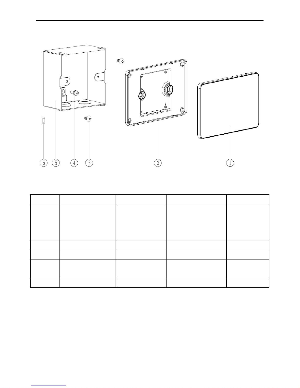
1 INSTALLATION INSTRUCTIONS
Fig.1.1 Parts of Centralized Controller
No.
① ② ③
④
Name
Touch screen of
controller
Rear cover of
controller
Self-tapping screw
ST4.2×9.5 MC
(Used to secure the
rear cover of
controller)
Screw
M4×12 (used
to secure
ground wire)
QTY 1 1 2 1
No.
⑤ ⑥
Name
Wiring box
installed in wall
Matching
resistance
QTY
1 1
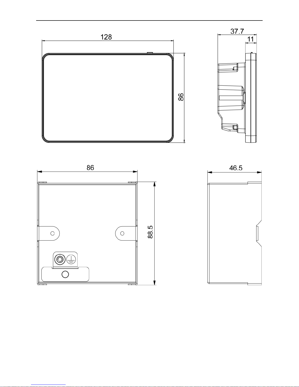
Unit: mm
E-Smart Zone Controller
2
Fig.1.2 Dimension of Centralized Controller
Fig.1.3 Dimension of Wiring Box Installed in Wall
E-Smart Zone Controller
3
1.1 Installation Requirements
(1)
Communication cord of the centralized controller must be selected according
to the table below. Never use the cable that is not in compliance with
instructions of this manual.
Networ
k
Cord type
Cord standard
Cord
size
(mm2)
Total
length of
communica
tion wire
L(m)
Remark
IDU
networ
k
(60227
IEC52/60227
IEC53)Shieldi
ng
light/Ordinary
polyvinyl
chloride
sheathed cord
IEC60227-5:20
07
≥2×0.75
L≤1000
If cord size is
2×1mm2,
communicati
on cord can
be stretched
longer. But
the total
length can’t
exceed
1500m.
ODU
networ
k
IEC60227-5:20
07
L≤250
The total
length of
communicati
on wire can’t
exceed
250m.
Note:
(1) The cord shall be Circular cord(the cores shall be twisted together).
(2) If unit is installed in places with intense magnetic field or strong
interference ,it is necessary to use shielded wire.
(3)
Never install the centralized controller in the following places:
1) Places with corrosive gas or serious dust, salt mist or oil smoke.
2) Wet and damp places or places with direct sunlight.
3) Places near high temperature objects or places where units might be splashed
by water.
E-Smart Zone Controller
4
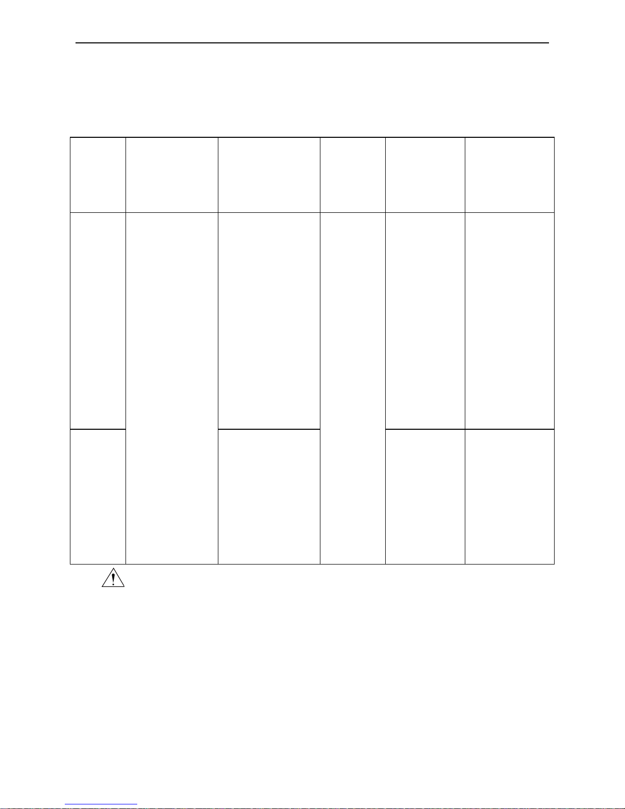
1.2 Wiring Instructions
1.2.1 Wiring Ports
Port
print
G1、G2
F1、F2
L、N
Meaning
CAN
communication
port
【
Reserved
】
Power
port
1.2.2 Power Supply
(1)
The centralized controller shall use independent power supply.
(2)
The range of input voltage: 110~240VAC; Frequency range: 50/60Hz.
(3)
Maximum rated power:3W.
(4)
The supply cord of this control can be replaced only by the manufacturer or
his accredited service agent.
(5)
Select power cord according to the following table. Never use the power cord
that is not in compliance with instructions of this manual.
Cord type
Cord standard
Cord size (mm2)
Single-core soft conductive
unsheathed cord(60227 IEC
08)
IEC 60227-3 2007
1.5
1.2.3 Connection Method
There are three methods to connect centralized controller with the air conditioning
system:
 Loading...