

Page 1

Owner's Manual
Original Instructions
Commercial Air Conditioners
Multi-VRF Centralized Controller
Model:
CE53-24/F(C)
Page 2

To Users
Thank you for selecting Gree’s product. Please read this instruction manual
carefully before installing and using the product, so as to master and correctly use
the product. In order to guide you to correctly install and use our product and
achieve expected operating effect, we hereby instruct as below:
(1) This appliance is not intended for use by persons (including children) with
reduced physical, sensory or mental capabilities, or lack of experience
and knowledge, unless they have been given supervision or instruction
concerning use of the appliance by a person responsibility for their safety.
Children should be supervised to ensure that they do not play with the
appliance.
(2) This instruction manual is a universal manual, some functions are only
applicable to particular product. All the illustrations and information in the
instruction manual are only for reference, and control interface should be
subject to actual operation.
(3) In order to make the product better, we will continuously conduct
improvement and innovation. We have the right to make necessary
revision to the product from time to time due to the reason of sales or
production, and reserve the right to revise the contents without further
notice.
(4) For personal injury or property loss and damage caused by improper
operation such as improper installation and debugging, unnecessary
maintenance, violation of related national laws and rules and industrial
standard, and violation of this instruction manual, etc., we will bear no
liability.
(5) The final right to interpret for this instruction manual belongs to Gree
Electric Appliances Inc. of Zhuhai.
Page 3

Contents
1 SAFETY NOTICES (PLEASE BE SURE TO ABIDE) ............................... 1
2 USER NOTICE ......................................................................................... 1
3 INSTALLATION ......................................................................................... 2
3.1 INSTALLATION REQUIREMENTS .............................................................. 3
3.2 WIRING INSTRUCTIONS ......................................................................... 4
3.3 WIRING INSTRUCTIONS ......................................................................... 8
3.4 REMOVAL PROCEDURE ......................................................................... 9
4 DISPLAY AND WORKING INSTRUCTIONS .......................................... 10
4.1 MAIN PAGE DISPLAY AND BUTTONS ..................................................... 10
4.2 GENERAL BUTTONS ............................................................................ 11
4.3 BUTTONS WORKING INSTRUCTIONS ..................................................... 11
5 FUNCTIONS DESCRIPTION ................................................................. 13
5.1 ALL ON/OFF ...................................................................................... 13
5.2 SINGLE UNIT CONTROL ....................................................................... 13
5.3 WATER/FLOOR CONTROL .................................................................... 17
5.4 FRESH AIR CONTROL .......................................................................... 21
5.5 E-CONTROL FUNCTION ........................................................................ 23
5.6 GROUP CONTROL ............................................................................... 24
5.7 SCHEDULE MANAGEMENT ................................................................... 26
5.8 LOCAL SETTING .................................................................................. 28
5.9 ENGINEERING SETTING ....................................................................... 30
5.10 OPERATION NOTICE .......................................................................... 31
6 ROOM VIEW ........................................................................................... 31
6.1 ALL ON/OFF ...................................................................................... 32
6.2 ROOM CONTROL ................................................................................ 32
Page 4
Multi-VRF Centralized Controller
1
1 Safety Notices (Please be sure to abide)
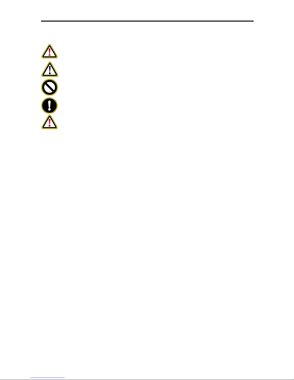
Warning: If not abide strictly, it may cause severe damage to the unit or
the people.
Note: If not abide strictly, it may cause slight or medium damage to the unit
or the people.
This sign indicates that the operation must be prohibited. Improper
operation may cause severe damage or death to people.
This sign indicates that the items must be observed. Improper operation
may cause damage to people or property.
WARNING!
This product can’t be installed at corrosive, inflammable or explosive
environment or the place with special requirements, such as kitchen.
Otherwise, it will affect the normal operation or shorten the service life of the
unit, or even cause fire hazard or serious injury. As for above special places,
please adopt special air conditioner with anti-corrosive or anti-explosion
function .
2 User Notice
All indoor units must be supplied with unified power.
Make sure communication cord is connected with the proper port, otherwise
there may occur communication malfunction.
Never knock on, throw or frequently detach the centralized controller.
Never operate the centralized controller with wet hands.
Never scratch the screen of centralized controller by hard or sharp objects.
If the centralized controller is connected with the outdoor network or the last
indoor unit of the indoor network, then a matching resistance must be
connected between G1 and G2 ports.
Page 5
Multi-VRF Centralized Controller
2
3 INSTALLATION
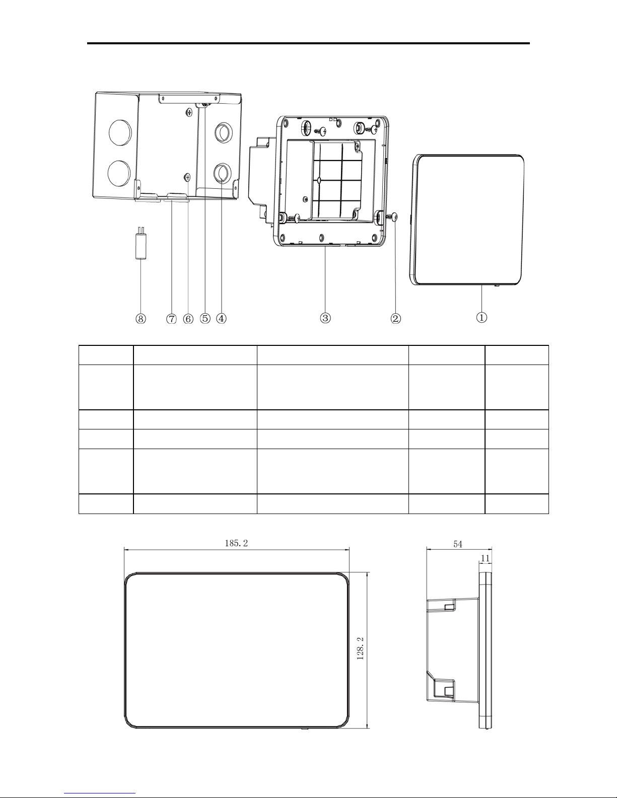
Fig.3.1 Parts of Centralized Controller
No.
①
②
③
④
Name
Touch screen
Self-tapping screw ST4.2
×
9.5 MC (used to secure the
rear cover of controller)
Rear cover
of controller
Rubber
band
QTY
1
4
1
6
No.
⑤
⑥
⑦
⑧
Name
Screw M4×12 (used
to secure ground
wire)
Screw ST4.2×16 FA (used
to secure electric box
cover)
Electric box
cover
Matching
resistanc
e
QTY
1
4
1
1
Unit: mm
Fig.3.2 Dimension of Centralized Controller
Page 6
Multi-VRF Centralized Controller
3
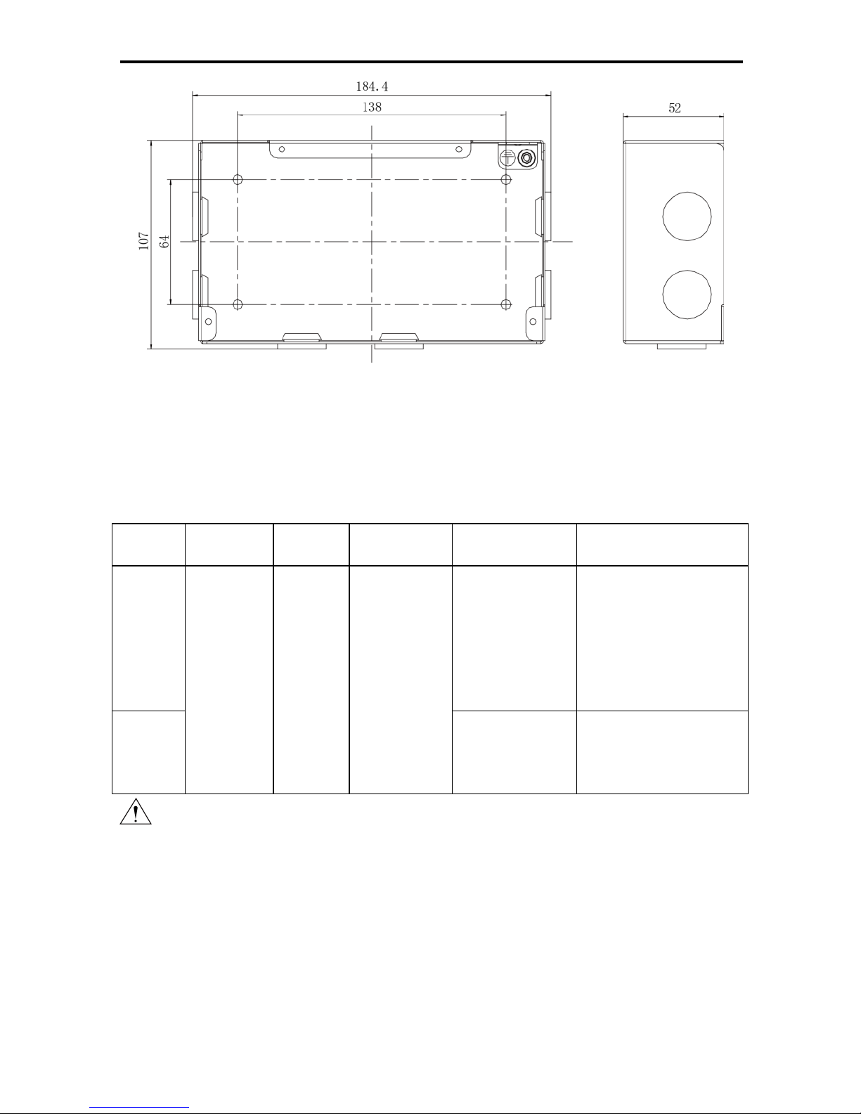
Fig.3.3 Dimension of Electric Box Cover
3.1 Installation Requirements
(1) Communication cord of the centralized controller must be selected
according to the table below. Never use the cable that is not in compliance
with instructions of this manual.
Network
Cord type
Cord
standard
Cord size
(mm2/AWG)
Total length
L(m/feet)
Remark
Indoor
network
Light/Ordin
ary
polyvinyl
chloride
sheathed
cord.
(60227
IEC 52
/60227 IEC
53)
IEC
602275:2007
2×0.75~
2×1.25
(2×AWG18~
2×AWG16)
L≤1000m
(L≤3280-5/6feet)
If cord size is 2×1mm2
(2×AWG16),communica
tion cord can be
stretched longer. But
the total length can’t
exceed
1500m(4921-1/4feet).
Outdoor
network
L≤500
(L≤820-1/5feet)
Total length of
communication cord
can’t exceed
500m(820-1/5feet).
Notice:
① The cord shall be Circular cord (the cores shall be twisted together).
② If unit is installed in places with intense magnetic field or strong
interference, it is necessary to use shielded wire.
(2) Never install the centralized controller in the following places:
1) Places with corrosive gas or serious dust, salt mist or oil smoke.
2) Wet and damp places, with direct sunlight.
3) Places near high temperature objects or places where units might be
splashed by water.
Page 7
Multi-VRF Centralized Controller
4
3.2 Wiring Instructions
(1) Wiring Ports
Port
print
G1, G2
F1, F2
A2, B2
A3, B3
L, N
Meaning
CAN
comm. port
【
reserved
port】
【
reserved port】
【
reserved port】
Power
port
(2) Power Supply
The smart centralized controller shall use independent power supply.
The range of input voltage: 100~240 VAC; Frequency range: 50/60Hz
Select power cord according to the following table. Never use the power cord
that is not in compliance with instructions of this manual.
Cord type
Cord standard
Cord size (mm2)
Single-cord soft conductiveunsheathed cord
(60227 IEC 08)
IEC 60227-3:2007
1.5
(3) Connection Method
There are three methods to connect centralized controller with the air
conditioning system.
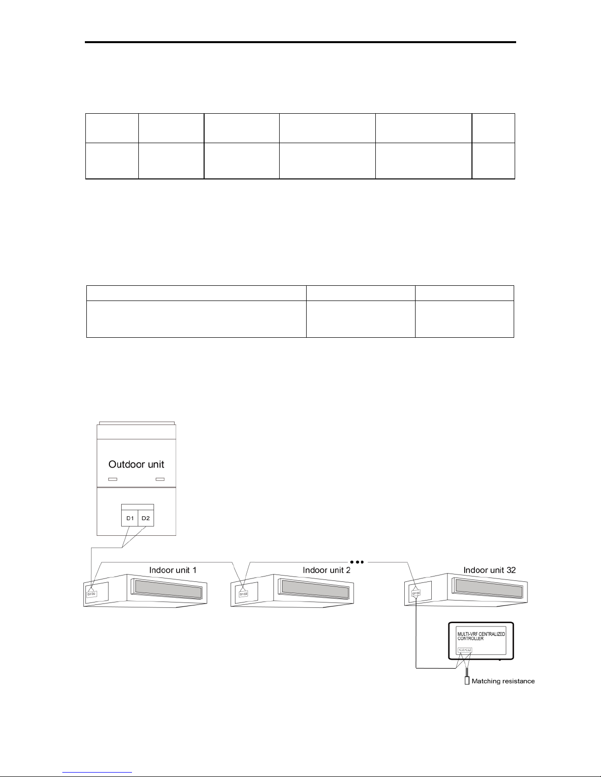
Method 1: Connect with indoor network
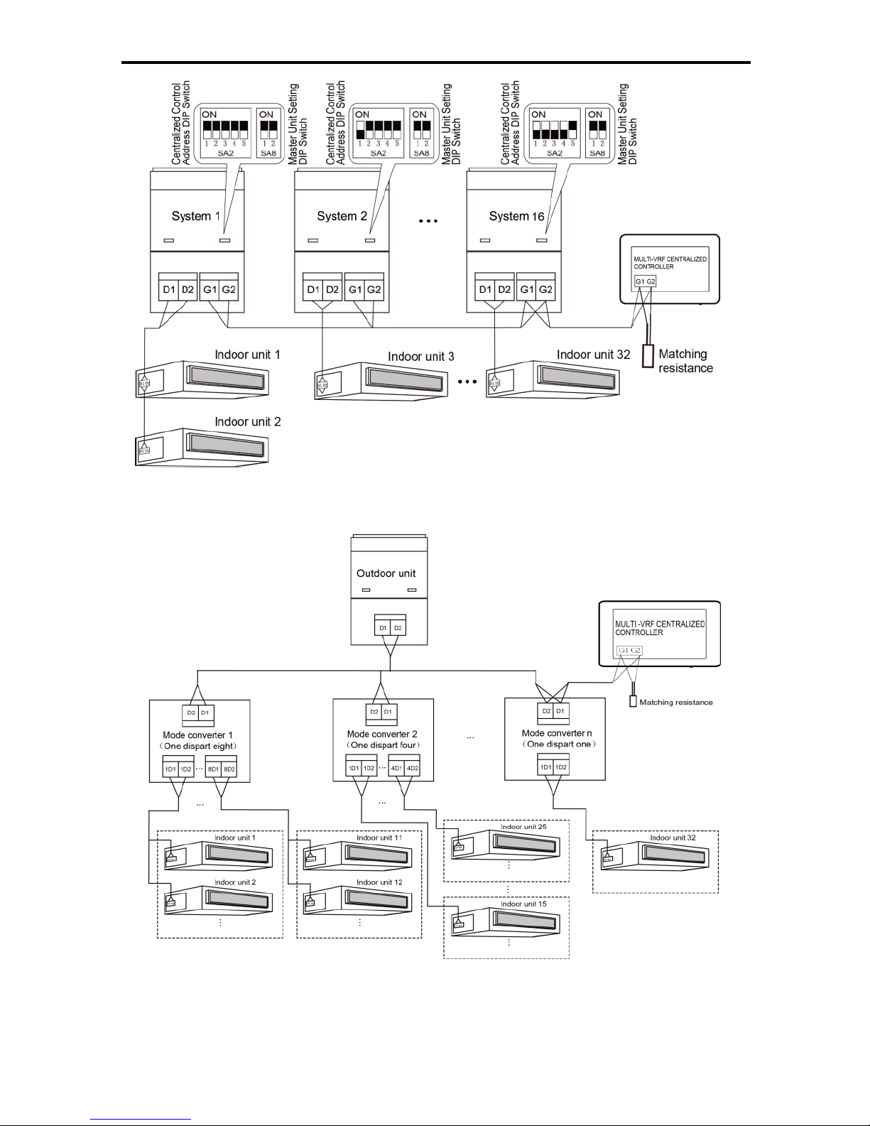
Fig.3.4 Centralized Controller Connected with Indoor Network
Method 2: Connect with outdoor network
Page 8
Multi-VRF Centralized Controller
5
Fig.3.5 Centralized Controller Connected with Outdoor Network
Method 3: Connect with heat recollection mode converter Network
Fig. 3.6 Centralized Controller Connected with Heat Recollection Mode Converter
Network
Wiring Instructions:
Page 9

Multi-VRF Centralized Controller
6
① The smart centralized controller is applicable to multi VRF units,
connectable with network of indoor units or the network of outdoor units or
mode converter network. One centralized controller can control up to 16
sets of outdoor system and up to 32 sets of indoor unit.
② If the centralized controller is to be connected with the network of indoor
units, connect according to fig.3.4. The controller can connect with any
one indoor unit in series, that is, connect the controller’s G1 and G2 ports
with the D1 and D2 ports correspondingly with communication cords.
When the controller is connected with the terminal unit of indoor network, a
matching resistance needs to be added with the communication cords at
the G1 and G2 ports.
③ If the centralized controller is to be connected with the network of outdoor
units, connect according to fig.3.5. The centralized controller can only be
connected with the terminal system of the outdoor network. A matching
resistance needs to be added with the communication cords at the G1 and
G2 ports.
④ The centralized control address DIP switch (SA2_Addr-CC) indicates the
centralized control address required when different refrigerating systems
are controlled in a centralized manner. The default factory setting is
"00000".
⑤ If the centralized controller is to be connected with the network of heat
recollection, connect according to Fig. 3.6. The method 2 is also
applicable to centralized controller switching in heat recollection network.
If the centralized controller is to be connected with the network of outdoor units,
set the DIP switch according to the following methods:
1) The DIP switch must be set on the master unit and set the Master Unit
Setting DIP Switch(SA8) to "00".Otherwise, the setting is invalid.
2) On the same refrigerating system, the centralized control address DIP
switch (SA2_Addr-CC) on a non-master unit is invalid, and it is
unnecessary to change the settings.
3) The centralized control address DIP switch (SA2_Addr- CC) on the master
unit of a refrigerating system must be set to “0000/”, and this system is the
master system.
4) The centralized control address DIP switch (SA2_Addr- CC) on the master
unit of other refrigerating systems must be set as follows:
Note: The centralized control address switch of DIP5 invalidation
Page 10
Multi-VRF Centralized Controller
7
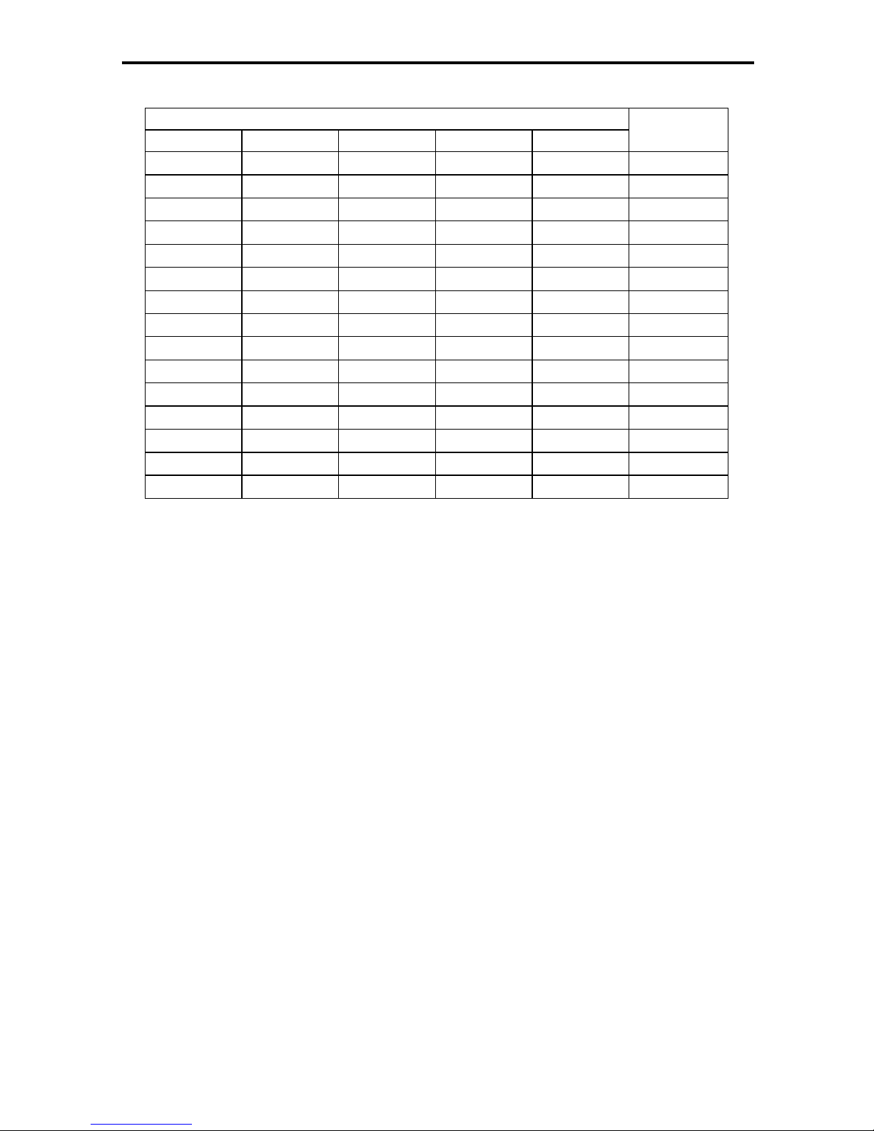
SA2
Address
NO.
DIP1
DIP2
DIP3
DIP4
DIP5
1 0 0 0 / 2 0 1 0 0 / 3 1 1 0 0 /
4
0 0 1 0 /
5
1 0 1 0 /
6
0 1 1 0 /
7
1 1 1 0 / 8 0 0 0 1 / 9 1 0 0 1 /
10
0 1 0 1 /
11
1 1 0 1 /
12
0 0 1 1 /
13
1 0 1 1 /
14
0 1 1 1 /
15
1 1 1 1 /
16
5) The centralized control address DIP switch (SA2_Addr- CC) cannot be the
same between different refrigerating systems. Otherwise, address
conflicts may occur and the unit cannot run properly.
6) If the address conflict occurs, it will popup the address conflict page.
Note:There are three ways to solve address conflict.
1: Enter into an unoccupied address by manually for the conflict address,
the address conflict can be solved after it set up success.
2: Press and hold the “Save” button for 5 seconds on the address conflict
page, select reset all the IDU’s address in the system, after entering the
engineering password, system will reassign all the address.
3: On the master unit of master system, press “SW3” to enter the
to-be-selected status of function settings, press “SW1 (UP)” or “SW2
(DOWN)” to select the function of “n5 ”, press “SW7” to enter “n5 ” function
settings, press “SW7” again to send the project number offset command.
Page 11
Multi-VRF Centralized Controller
8
3.3 Wiring Instructions
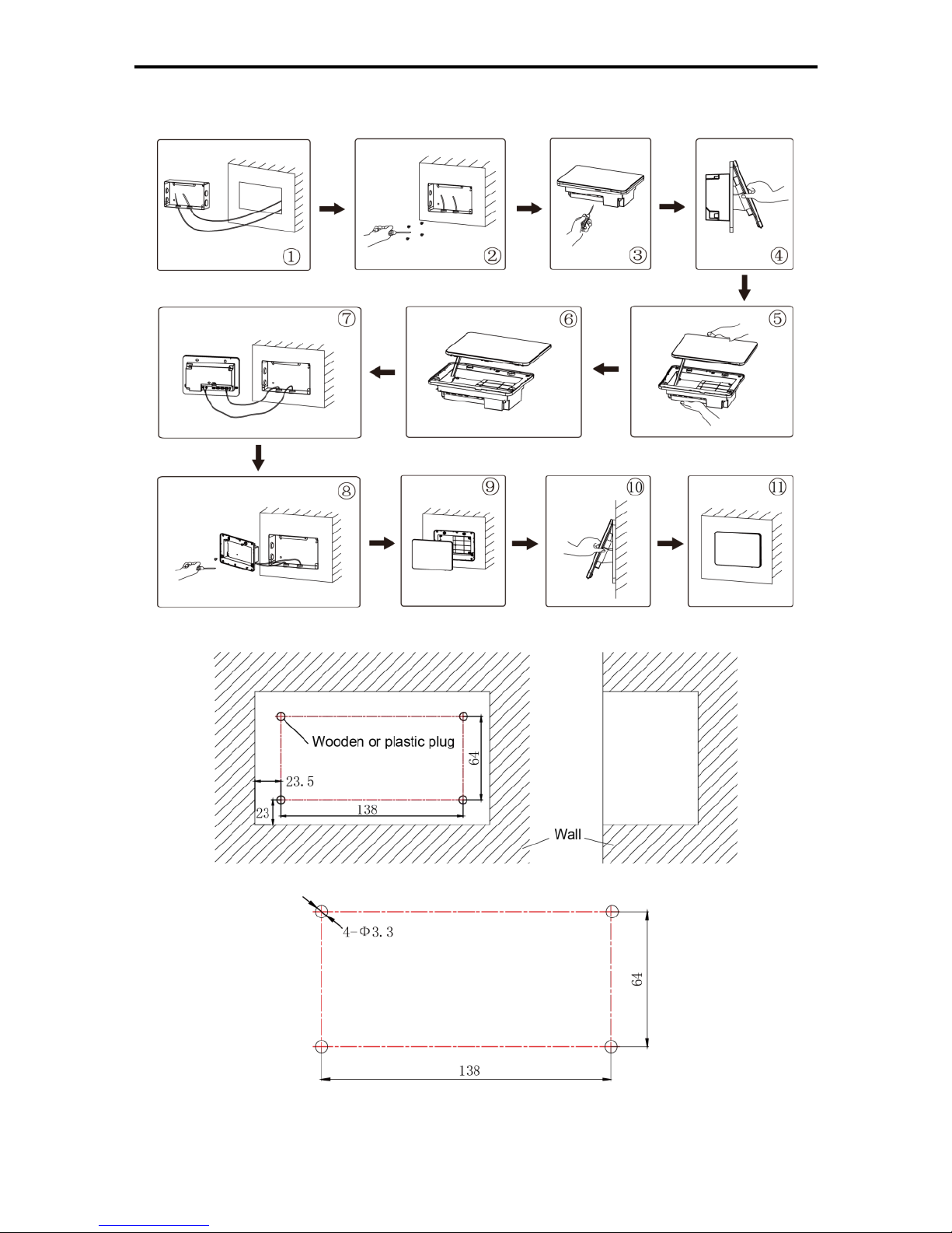
Fig.3.7 Installation Diagram
Fig.3.8 Diagram of Wooden or Plastic Plug
Fig. 3.9 Installation Holes of the Electric Box Rear Cover
Fig.3.7 is a simple installation procedure of centralized controller. Please pay
Page 12
Multi-VRF Centralized Controller
9
attention to the following matters:
(1) Before installation, first cut off the power supply of indoor unit. The power
must be cut off during the whole installation process.
(2) During the installation, be careful not to damage to touch screen.
(3) Before installation, please make the following preparations:
1) In case that the centralized controller is installed on wall, dig a hole that is
the size of 180mm×107mm×62mm and peg 4 wooden or plastic plugs
on the wall according to fig.3.8.
2) In case that the centralized controller is installed inside the control cabinet,
dig 4 installation holes on the surface of the control cabinet according to
fig.3.9.
(4) In step (1), pull out the power core and communication cord, and then lead
them separately from the wire orifice of the electric box rear cover. Never
lead the cords through a same orifice.
(5) In step (2), locate the electric box rear cover to the installation holes of the
wall with screw ST4.2×16 FA.
(6) In step (6), pull out the wire connecting the touch screen and controller’s
rear cover. Put the touch screen on a safe place.
(7) In step (7), connect the communication cords to G1, G2 terminals, and
connect the neutral wire and live wire to the N, L terminal; connect the
ground wire to position on the electric box rear cover. Secure it with
screw M4×12.
(8) In step (8), locate the controller’s rear cover onto the electric box rear
cover with screw ST4.2×9.5 TC.
(9) In step (9), connect the wire between touch screen and controller’s rear
cover.
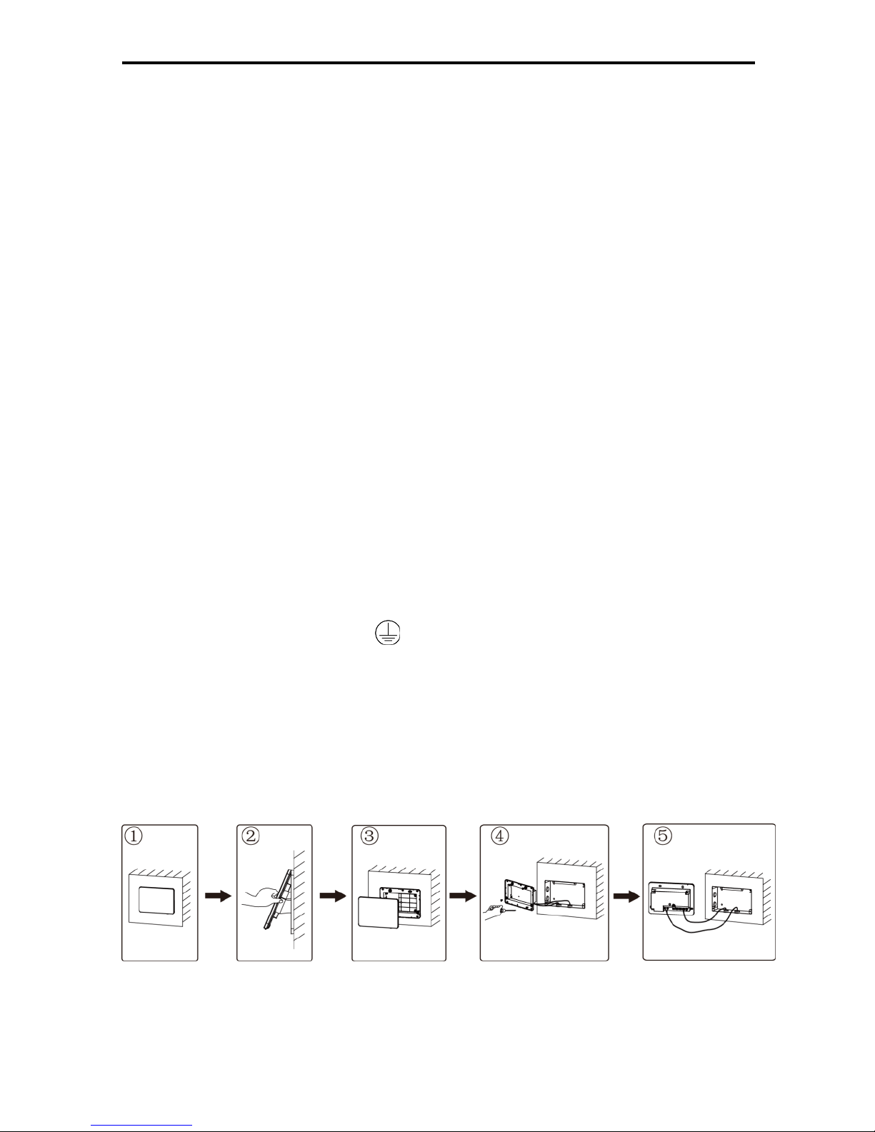
3.4 Removal Procedure
Fig.3.10 Diagram of Removal
Page 13
Multi-VRF Centralized Controller
10
4 DISPLAY AND WORKING INSTRUCTIONS
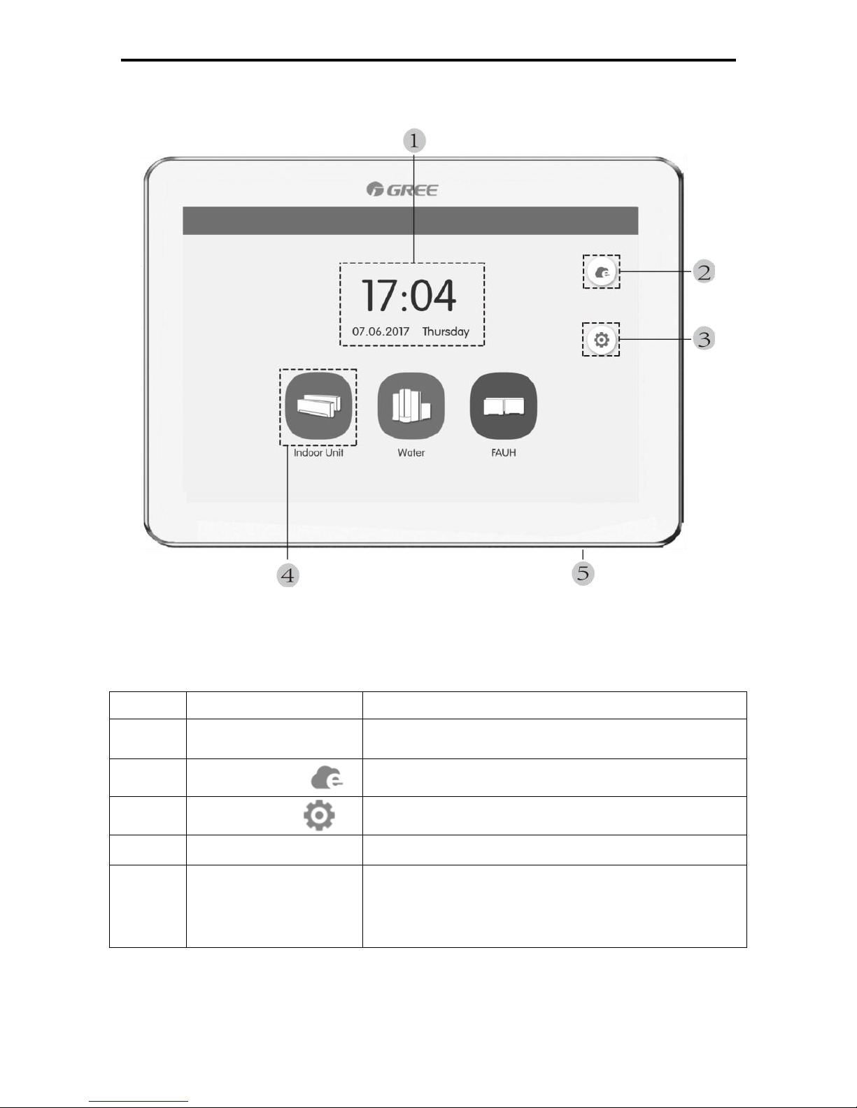
Fig.4.1 Main Page
4.1 Main Page Display and Buttons
No.
Name
Instructions
1
Time zone
The present date, week and time
2
e-Control button
Press this button to enter e-Control page
3
Setting button
Press this button to enter setting page
4
Unit button
Press this button to enter IDU page or Water/Floor page
5
Touch button
Press the Touch Button to turn on/off the screen of
centralized controller.
Press and hold the Touch Button for 5sec to restart to
centralized controller.
Page 14
Multi-VRF Centralized Controller
11
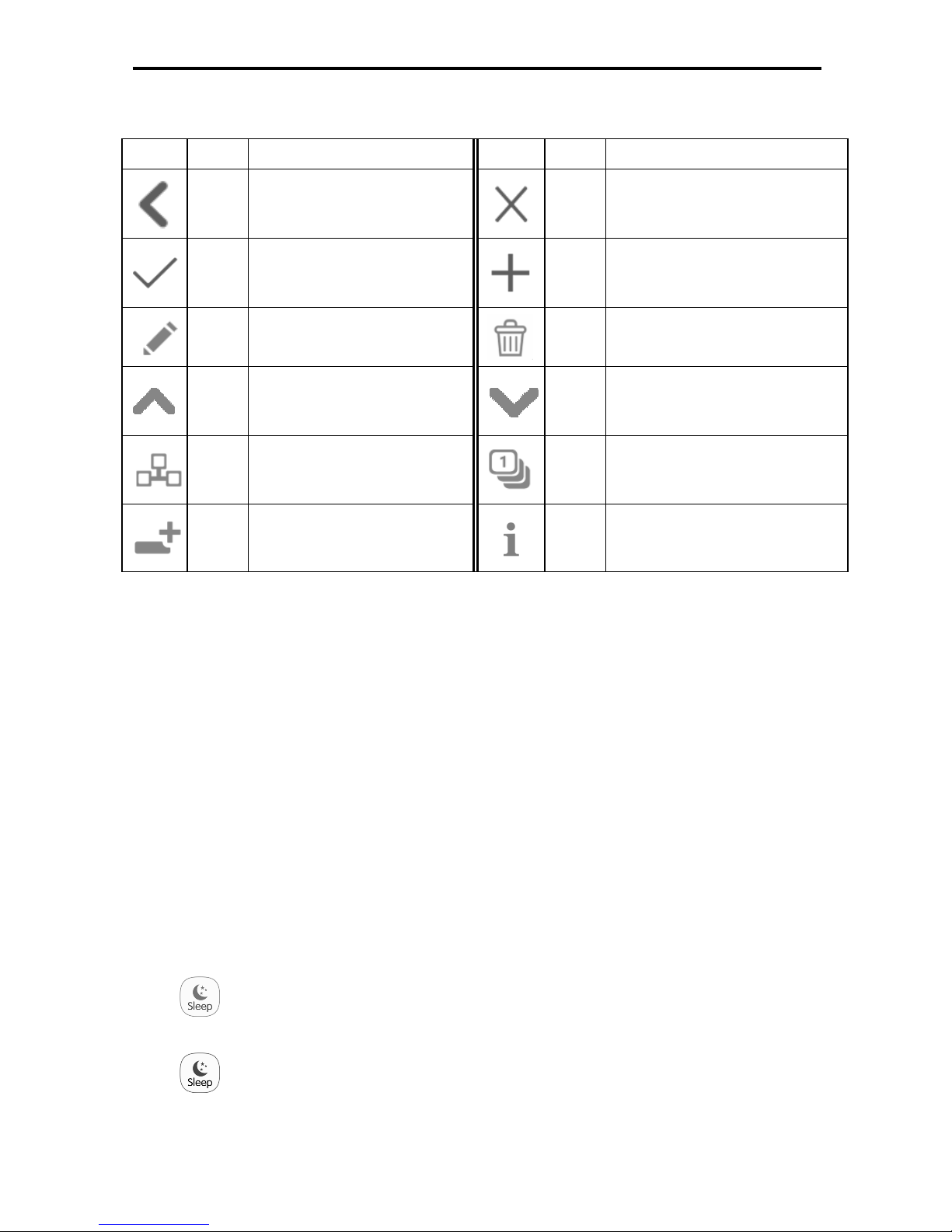
4.2 General Buttons
Display
Name
Meaning
Display
Name
Meaning
Return
Press this button to return to
the previous page
Cancel
Press this button to cancel the
current setting and return to the
previous page
Save
Press this button to save the
current setting and return to
the previous page
Add
Press this button to add group
or schedule
Edit
Press this button to edit the
e-Control,group or schedule
Delete
Press this button to delete
group or schedule
Up
Press this button to increase
value or select the previous
option
Down
Press this button to decrease
value or select the next option
Group
Control
Press this button to enter
Group control page
IDU
Sort
Press this button to enter IDU
sort page
Add
IDU
Press this button to enter Add
IDU page
Info
Press this button to enter Info
page
4.3 Buttons Working Instructions
The centralized controller uses a capacitive touch screen so that user can
operate the units by just touching the screen.
Buttons on the screen are presented in the following ways:
(1) Icon
Icon button can be operated directly. See section 4.2 for more details.
(2) Icon + Text
According to the meaning of Text, turn on or off or select a certain function, or
enter a certain page. This type of button has 2 or 3 kinds of status based on the
specific function.
Meaning of status (take Sleep Button as an example):
Thin light indicates invalid/not selectable. Sleep function is invalid and
can’t be selected. Different cases for models.
Light indicates off/not selected. Sleep function is off. Pressing the grey
sleep button can turn on the sleep function.
Page 15
Multi-VRF Centralized Controller
12
Dark indicates on/selected. Sleep function is on. Pressing the orange
sleep button can turn off the sleep function.
(3) Sliding
Sliding left/right or up/down can turn over the page. For example the home
page list of indoor units, schedule, etc.
(4) Sliding bar
Press and hold the sliding bar to drag up/down or left/right and to adjust the
value. For example the fan speed setting, backlight setting, etc.
(5) Zone button
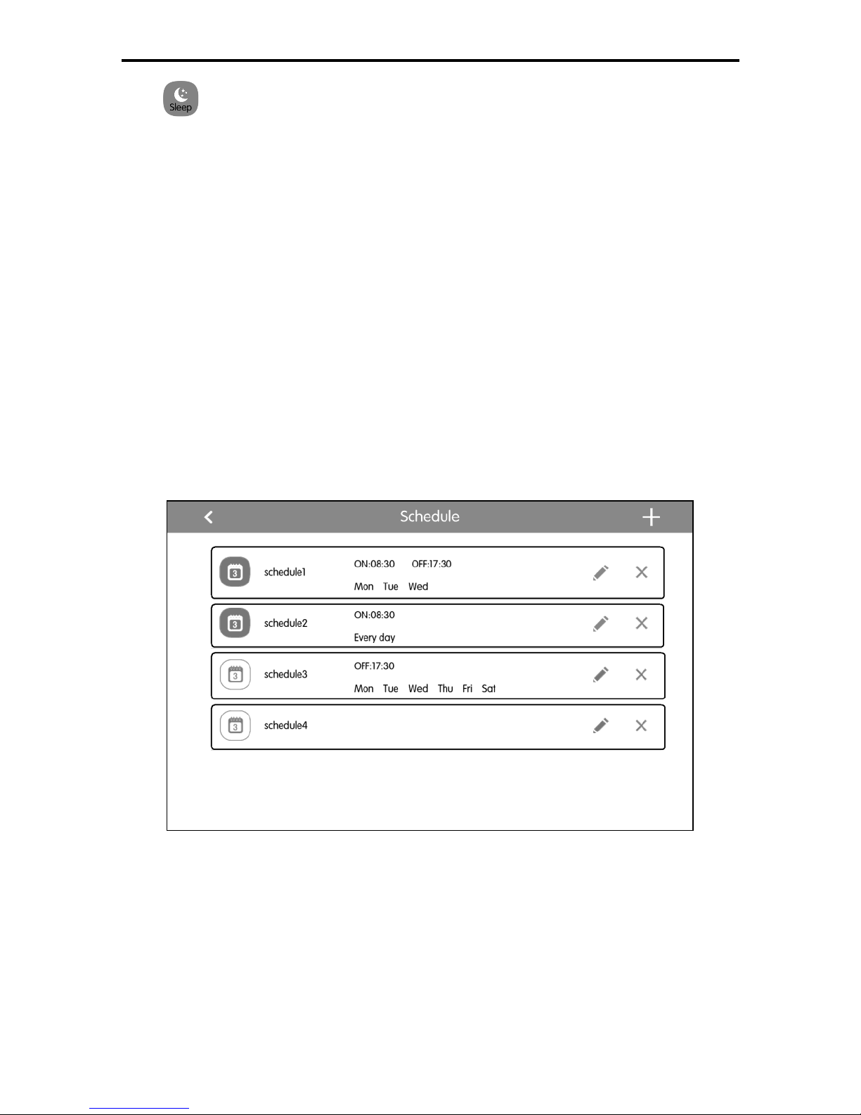
On the management pages of e-Control functions and schedule, as indicated in
fig.4.2 (the home page of schedule), each rectangle frame constitutes a zone
button.
Press the zone button, then the turning on/off of corresponding function or the
corresponding page will pop in.
Fig.4.2 Zone Buttons on the Group Control Page
Page 16
Multi-VRF Centralized Controller
13
5 FUNCTIONS DESCRIPTION
5.1 All ON/OFF
On the home page, press the “Indoor Unit“ button to enter IDU home page,
swith to “ALL IDU” option, press the “GroupOFF” button to turn off all indoor units.
Also press the “GroupON” button to turn on all indoor units. Then indoor units
will work according to memory.
5.2 Single Unit Control
On the IDU home page, press the icon of indoor unit to enter the single unit
control.
Press the icon of indoor unit for 5 seconds to pop up the name set of the
selected indoor unit.
Parameters of single unit control include parameters of general control and
advanced control.
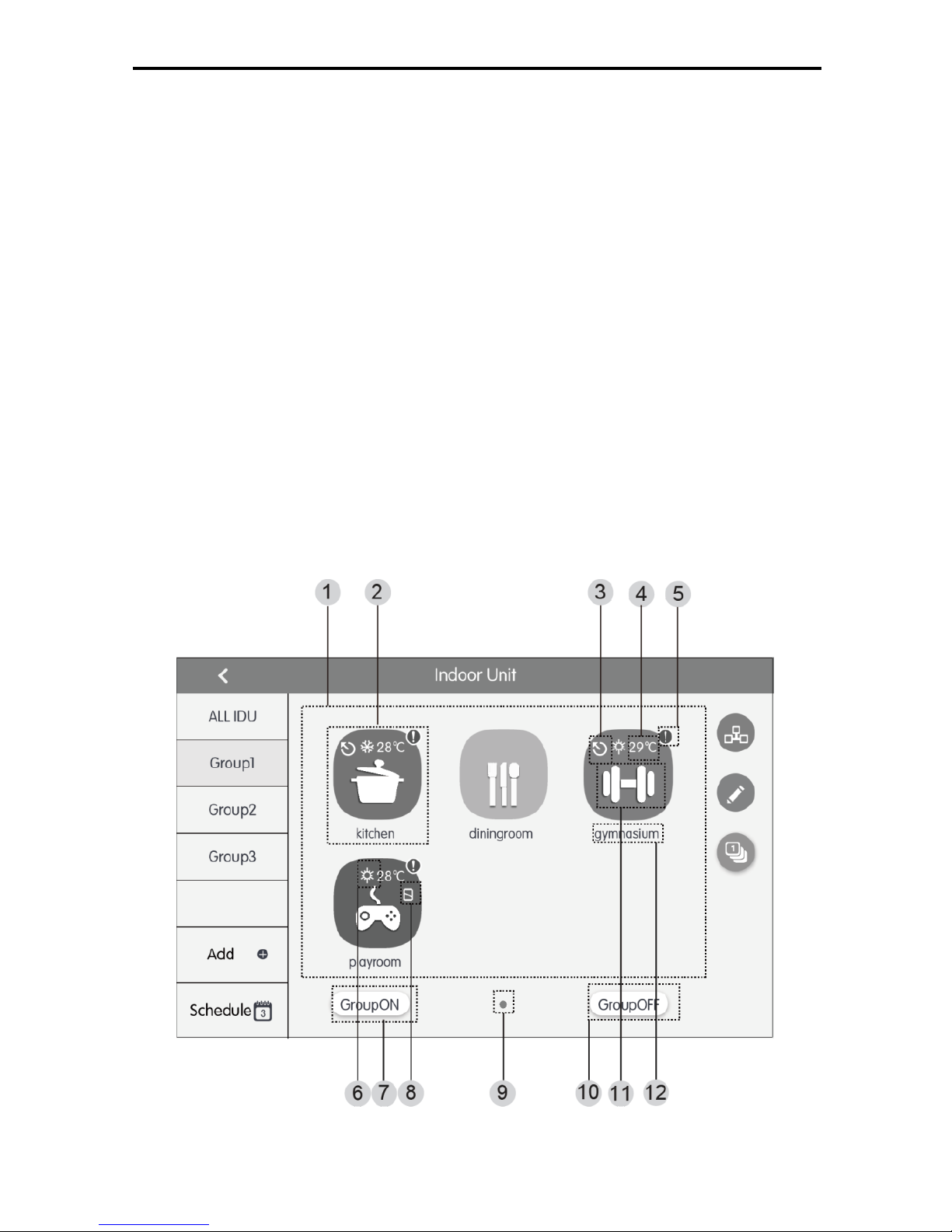
Fig.5.1 Page of IDU home page
Page 17
Multi-VRF Centralized Controller
14
No.
Name
Instructions
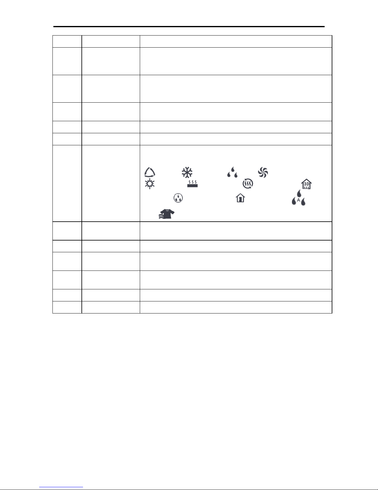
1
IDU display
Display in separate page the list of indoor units that are
controlled by the centralized controller. Sliding left or right can
turn over the page.
2
IDU icon
Press the button to enter the page of indoor unit control.
Light icon indicates that IDU is on while the dark icon indicated
that IDU is off.
3
Master IDU
This icon will be displayed when indoor unit is the master indoor
unit of the system.
4
Set temperature
When indoor unit is on, set temperature will be displayed here.
5
Error status
Error icon will be displayed if indoor unit is malfunctioning.
6
Operation mode
When indoor unit is on, the current operation mode will be
displayed:
Auto Cooling Dry Fan
Heating Floor heating
Space heating
3D
heating
Refreshing Absence Auto
dry Dry Cloth
7
Group on button
Press this button to turn on all air conditioning equipment of the
group.
8
Shield status
This icon will be displayed when indoor unit is in shield status.
9
Current page
The total pages of the controlled indoor unit and the current
page.
10
Group off button
Press this button to turn off all air conditioning equipment of the
group.
11
IDU icon
Display the icon of the indoor unit.
12
IDU name
Display the name of the indoor unit.
Page 18
Multi-VRF Centralized Controller
15
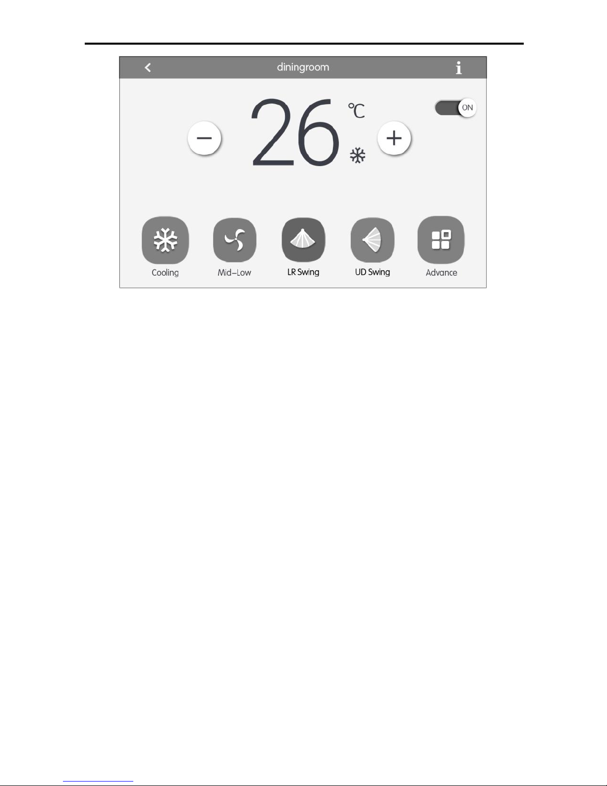
Fig.5.2 Page of Single IDU Control
(1) General Control Parameters
1) On/off
Press the on/off button to turn unit on or off.
When unit is turned off, mode, temperature,fan speed and swing can’t be set.
2) Mode setting
Press the Mode buttons to set unit’s operation mode.
Modes for indoor units of different series are not all the same.
If a certain mode is not available in the indoor unit, the icon of the
corresponding mode cannot be selected.
Note:
① Only master indoor unit can set auto mode; absence mode can be set only
when one indoor unit is turned on and this indoor unit shall be the bedroom
indoor unit with three refrigerant pipes.
② Heat recollection system have no master indoor unit. When the indoor unit
of the same branch is connected into one indoor unit, the auto mode can
be set; when the quantity of indoor unit in the same branch is more than
one set, the auto mode cannot be set; other modes can be freely switched.
3) Temperature setting
Press the up or down buttons to adjust temperature. Each time pressing the
button will increase/decrease the temperature by 1. Holding down the button can
increase/decrease temperature continuously.
Page 19

Multi-VRF Centralized Controller
16
Pressing the button can display the “indoor temp” and “outdoor temp”.
Note:For Bedroom IDU, Press the up or down buttons to adjust temperature.
Each time pressing the button will increase/decrease the temperature by 0.5.
4) Humidity setting
Press temperature and humidity switching button to switch to the humidity
setting interface. Press the up or down button to adjust humidity. Each time
pressing the button will increase/decrease the humidity by 5%. Holding down the
button can increase/decrease humidity continuously within the range from 45% to
65%.
Note: Humidity Setting function is particular for Bedroom air condition. other air
condition without Humidity Setting function.
5) Fan speed setting
Press or drag the fan speed bar to set unit’s fan speed.
Note: Unit defaults to low fan speed in dry mode. Fan speed cannot be set in
drying or floor heating mode.
Auto fan speed is defaulted in absence mode and fan speed cannot be set; low
fan speed is defaulted in auto dry mode and cannot be set; high fan speed is
defaulted in clothes drying mode and cannot be set.
6) Swing setting
Pressing the button “Up-Down Swing” or “Left-Right Swing” can turn on or off
the swing function.
Note: Swing types for indoor units of different series are not all the same.
7) Malfunction View
When indoor unit fails to function well, press the button to view the
information of malfunctions.
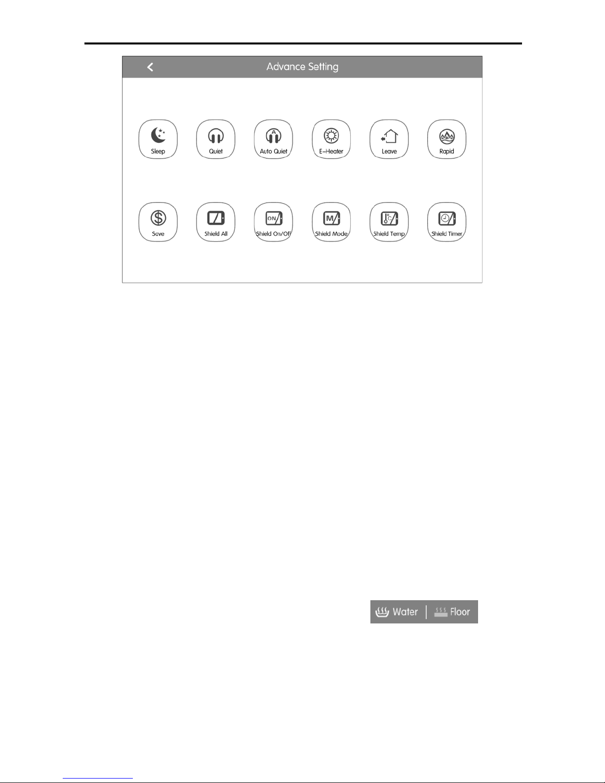
(2) Advanced Control Parameters
Press Advance Button to enter the advance page.
Press icon buttons to turn on or off the corresponding function.
Page 20
Multi-VRF Centralized Controller
17
Fig.5.3 Advance Page
1) Functions of Sleep, Quiet, E-Heater, Absence and Rapid can only be
effective when unit is turned on.
2) When sleep function is on, quiet function will be turned on subsequently.
Sleep function will not be effective under auto, fan or floor heating mode.
3) Absence function can only be turned on in heating mode. When absence
function is on, set temperature is 8℃.
4) Rapid cool function can only be effective in cool mode. Likewise, rapid
heat function can only be effective in heat mode.
5) When shield all function is on, other shield buttons will be invalid.
6) When Shield Temp function is on, Sleep function is off.
5.3 Water/Floor control
On the water/floor home page, press the icon of water/floor unit to enter the
water/floor control interface.Press the icon of water/floor unit for 5 seconds to pop
up the name set of the selected indoor unit.
Water/Floor control parameters include water heating control parameter and
floor heating control parameter. It can be switched via button.
Notes:
① When there is only one function can be selected (water or floor), it can only
display the water heating or floor heating function interface, and cannot be
switched to another interface;
② Only when it is connected to hot water generator, water heating and floor
heating functions are applicable, the interface can be switched and
Page 21
Multi-VRF Centralized Controller
18
displaced according to the above instructions;
5.3.1 Water Control Parameter
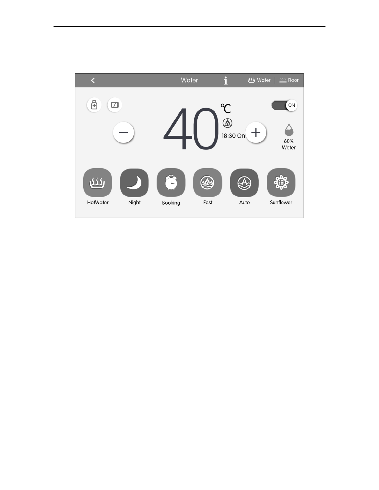
Fig. 5.4 Page of Water heating Control
(1)
On/Off
Press the on/off button to trun unit on or off.
When the unit is off, it cannot set the mode, temperature and preset function,
while it can set the sterilization function.
(2)
Mode Setting
Press the Mode buttons to set unit’s operation mode.
There are three modes: HotWater, Booking, Night. These three modes can not
be simultaneously conducted, it can only choose one of the modes.
HotWater mode: the water tank or hot water generator will start up or stop
heating water according to the current set water temperature.
Booking mode: book the water heating time, the water tank or hot water
generator will start up the unit in advance according to the actual water temperature,
and will decide the on and off of water tank or hot water generator according to the
temperature difference between actual water temperature and the setting water
temperature. The water tank or hot water generator will close down the unit 1~4
hours later after the preset time. Once this mode is set, it will circularly operate
every day.
Night mode: the fixed period for providing hot water is from 00:00 to 06:00, the
Page 22
Multi-VRF Centralized Controller
19
water tank or hot water generator will start up in this period, and will decide the on
and off of water tank or hot water generator according to the temperature difference
between actual water temperature and the setting water temperature. If it is not
within this period, the water tank or hot water generator will close down the unit.
Once this mode is set, it will circularly operate every day.
(3)
Temperature Setting
It displays the current temperature of hot water as default. The temperature
value will turn to the setting temperature and can be adjusted by pressing
and buttons; the temperature value will increase or decrease by every
pressing the button for once. The temperature value will be continuously increased
or decreased by long pressing the button.After 5 seconds without any action, the
temperature value will turn back to the current temperature.
Under the standard HotWater, Booking and Night modes, the temperature
setting range is: 35
℃~
the maximal adjustable temperature 55℃, the acquiescence
maximal temperature is 50℃.
(4)
Available Hot Water Volume
The water volume can be display in real time, there are five sections of water
volume: 100%, 80%, 60%, 40%, 20%, when the water volume is less than 20%, it
will flicker.
(5)
Function Setting of Water Heating
Under on /off status of water heating, the following functions can be set:
Water On/Off
Functions
Start-up Water mode
Sunflower, Auto, Sterilization, Fast, Shield
Start-up Booking mode
Auto, Sterilization, Fast, Shield
Start-up Night mode
Auto,Sterilization, Fast, Shield
Water heating off
Sterilization
Sunflower function: find the highest outdoor temperature by recording the
history data of outdoor temperature to define the time to heat the water, so as to
achieve energy saving.
Auto function: the setting temperature of water heating will be automatically
provided by water heater according to the outdoor ambient temperature, there is no
need to set by the user, and the water temperature cannot be adjusted via or
buttons.
Sterilization function: it will conduct high temperature sterilization when the
water temperature in the water tank is heated to 65~70℃ (adjustable) within the
Page 23
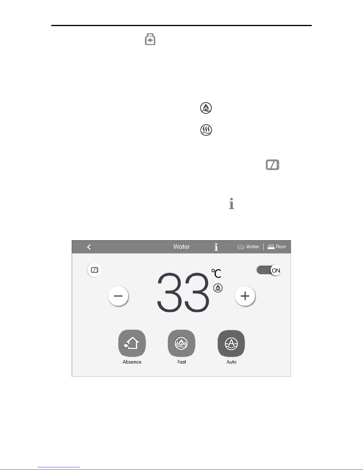
Multi-VRF Centralized Controller
20
required set time. Press the button to enter the sterilize page,when the high
temperature sterilization is set to be “once”, then the sterilization will be valid for
once; when the high temperature sterilization is set to be “circular”, the sterilization
will be circularly valid, then it can set the circulated days and presetting sterilization
time. When the sterilization function is activated, the icon will flicker.
Fast function: start up the compressor and electric heating water under the
allowable conditions of outdoor unit, it displays ,the fast water heating function
can be set to be valid for once, when the water tank/hot water generator has
reached to heat preservation status, it displays ,the fast water heating function
will be cancelled for energy saving. After the water heating is closed down, the fast
water heating function is cancelled.
Shield function: it can conduct shield function by pressing of wired
controller to nullify such operation.
(6)
Malfunction View
When the water heater fails to function well, press to view the information
of malfunctions.
5.3.2 Floor control parameter
Fig. 5.5 Page of Floor Heating Control
(1)
On/off
Press the on/off button to trun unit on or off.
When the unit is off, the mode and temperature cannot be set.
(2)
Temperature Setting
Page 24
Multi-VRF Centralized Controller
21
It displays the current water yielding temperature as default. The temperature
value will turn to the setting temperature and can be adjusted by pressing
and buttons; the temperature value will increase or decrease by every
pressing the button for once. The temperature value will be continuously increased
or decreased by long pressing the button.After 5 seconds without any action, the
temperature value will turn back to the current water yielding temperature.
Floor heating water yielding temperature range: 25℃~the highest water
yielding temperature of floor heating 45℃.
(3)
Function Setting of Floor Heating
Under the on/off status of floor heating, the functions can be set as below:
Floor on/off
Function
Remarks
Floor on
Auto, Fast, Absence, Shield
Floor off
Absence
It will be valid only when the indoor
unit is set together with shunt valve
Auto function:the floor heating water yielding temperature will be automatically
provided by hot water generator according to the outdoor ambient temperature,
there is no need to set by the user, and the water temperature cannot be adjusted
via or buttons.
Fast function: start up the compressor and electric heating under the allowable
conditions of outdoor unit.
Absence function: when the user is absence, it will maintain certain degree of
water temperature to prevent the pipelines from being frozen up and prevent the
indoor equipment from being destroyed.
Shield function: it can conduct shield function by pressing of wired
controller to nullify such operation.
(4)
Malfunction View
When the floor heating fails to function well, press button to view the
information of malfunctions.
5.4 Fresh Air Control
On fresh air homepage, press the fresh air icon for 5 seconds to pop up the
fresh air name, project number and icon settings; click fresh air icon to enter fresh
air control interface.
Page 25
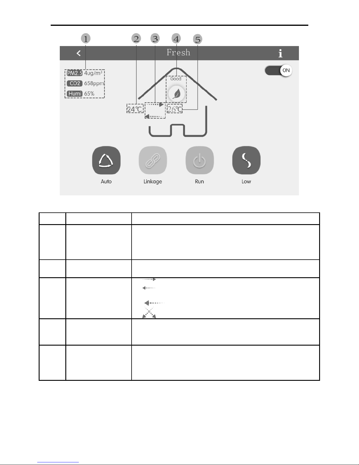
Multi-VRF Centralized Controller
22
Fig. 5.6 Page of Fresh Air Control
No.
Name
Instruction
①
Parameter
display zone of
air box
Display indoor PM2.5, CO2 and humidity. “- -” will be
displayed when air box is not connected
Upper and lower limits of PM2.5, CO2 and humidity
display keep the same as those in Section 6.2.5
②
Fresh air inlet
temperature
Display fresh air inlet temperature
③
Unit operation
mode
Means bypass mode or low
temperature mode
Means discharge mode
Means heat exchange mode
④
Air quality class
Air quality is classified into six classes, which are
excellent, good, moderate, bad, heavy pollution, serious
pollution
⑤
Return air inlet
temperature/fresh
air outlet
temperature
Display fresh air return temperature/fresh air outlet
temperature
(1)
On/Off
Press On/Off button to turn on or turn off the unit.
When the unit is off, mode and fan speed cannot be set. Operation mode and
inlet fresh air temperature are not displayed.
Page 26
Multi-VRF Centralized Controller
23
Note: The fresh air unit which is connected with air box will display PM2.5, CO2,
indoor humidity and air quality class; when air box is not connected, PM2.5, CO2
and indoor humidity will display “- -”. Air quality class will be concealed.
(2)
Mode setting
Press Mode button to set control mode.
Note: Only the fresh air unit which is connected with air box can set auto mode.
The fresh air unit which is not connected with air box cannot select auto mode.
(3)
Fan speed setting
Click Fan Speed button to set fan speed.
Note: Auto fan speed can be selected only in auto mode.
(4)
Error inquiry
When fresh air unit occurs error, click to check detailed error information.
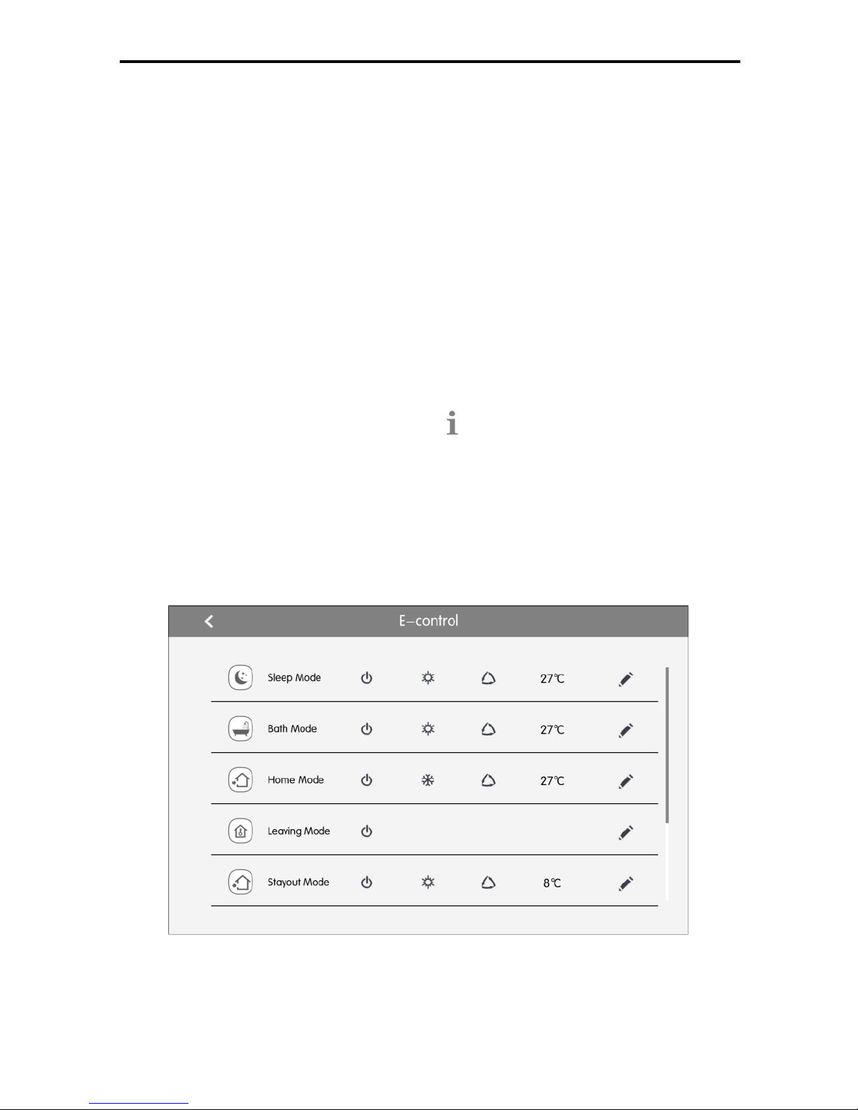
5.5 e-Control Function
On the home page, pressing e-Control button can enter the page of e-Control.
e-Control includes 5 short-cut modes (Sleep, Bath, Home, Leaving and Stay
out) and 3 DIY modes.
User may reset the functions of different modes according to actual needs.
Fig.5.7 e-Control Page
(1) Turn on e-Control
Pressing the zone button can turn on the selected short-cut mode.
Page 27
Multi-VRF Centralized Controller
24
Note: e-Control can be turned on repeatedly. When it is turned on, centralized
controller will send out one control order according to the mode setting.
(2)
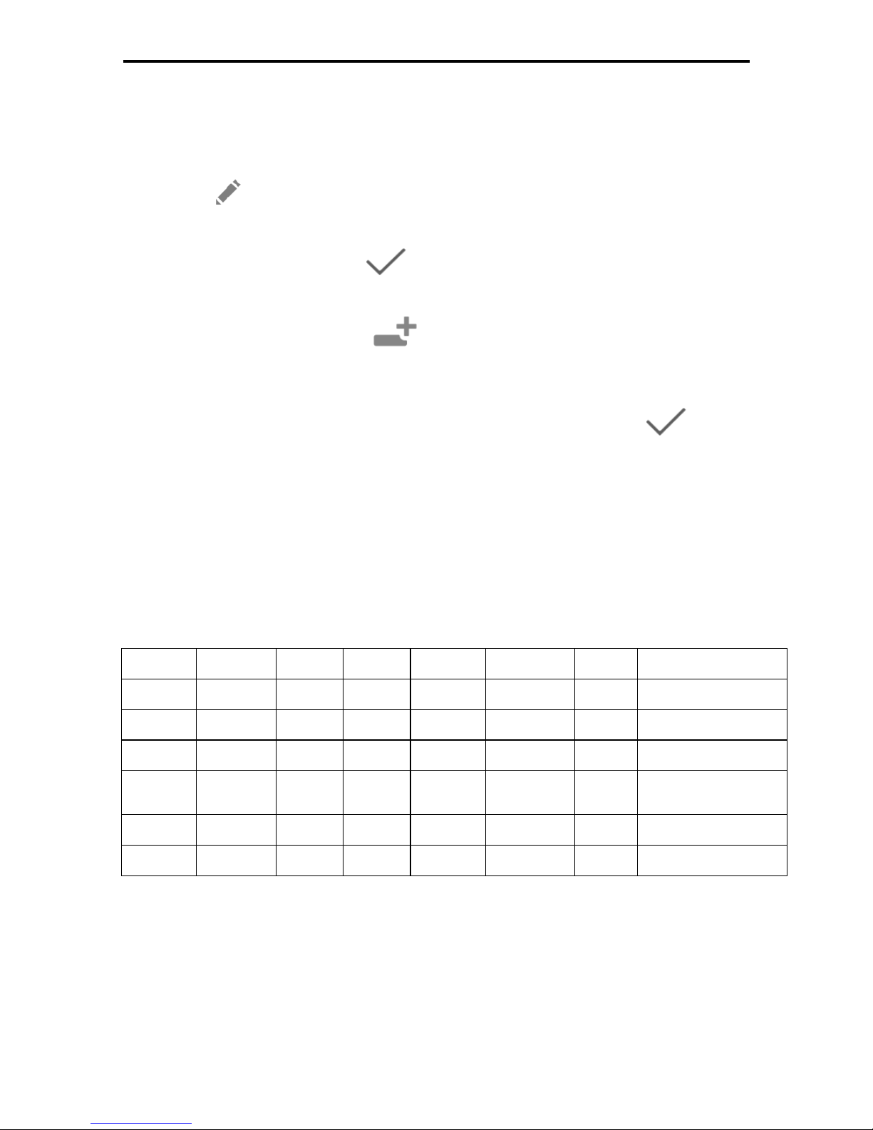
Edit e-Control
Press to edit the mode parameters.
Settings of mode parameters are the same as single unit control.
After setting is done, press to save the setting.
(3) Add equipment
On the edition page, press
and then the page of equipment selection
will pop in.
User can set the indoor unit that works according to the current modes.
Pressing the icon of indoor unit can select or cancel the unit. Press to save
the setting.
Note: For a same indoor unit, different modes can be set at the same time. In
this case, indoor unit will work according to the latest energized mode.
(4) Restore default settings
On the edition page, press the “Reset Default” button to restore the ex-factory
default settings.
Ex-factory default settings:
Mode
Subject
On/off
Mode
Set temp
Fan speed
Swing
Function
Sleep
All IDUs
On
Heat
27℃
Auto
Off
Turn on sleep function
Home
All IDUs
On
Cool
27℃
Auto
Off
--
Leaving
All IDUs
Off
--
--
--
--
--
Stayout
All IDUs
On
Heat
8℃
Auto
Off
Turn on the stay-out
function
Bath
All IDUs
On
Heat
27℃
Auto
Off
--
DIY
All IDUs
On
Heat
27℃
Auto
Off
--
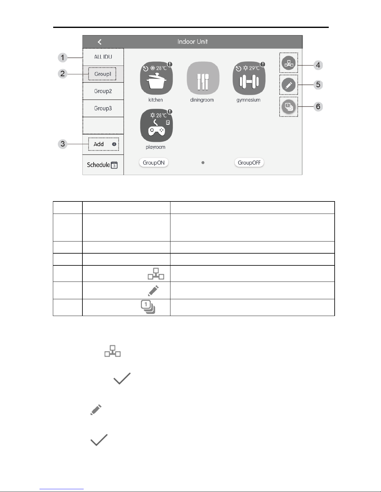
5.6 Group Control
Press the IDU button on the home page to enter the page of group function.
Page 28
Multi-VRF Centralized Controller
25
Fig.5.8 Group Page
No.
Name
Instructions
①
Group display
Display in separate page the list of groups that are
controlled by the centralized controller. Sliding up or
down can turn over the page.
②
Group names
Display the names of every group.
③
Add group button
Press the button to add a group.
④
Group control button
Press the button to enter the group control page.
⑤
Group edit button
Press the button to enter the group edit page.
⑥
IDU sort button
Press the button to enter the group sort page.
(1) Group control
Press the
button to enter the page of group control. Control parameters
are the same as single unit control.
Press button to send out the group control order.
(2) Edit group
Press to enter the page of group editing.
Use can set the group name and add indoor units to the group.
Press to save the setting.
Note: 1 set of indoor unit can be set in up to 5 groups
Page 29
Multi-VRF Centralized Controller
26
(3) IDU sort
Press the button to enter the IDU sort page.
Select one indoor unit, press the left of right button at the buttom of the screen
to switch the display of the indoor units.
(4) Add group
Press the button to add new groups. Then the page of group editing will
pop in. User can set the group name and add indoor units to the group.
(5) Delete group
Press to delete the selected group.
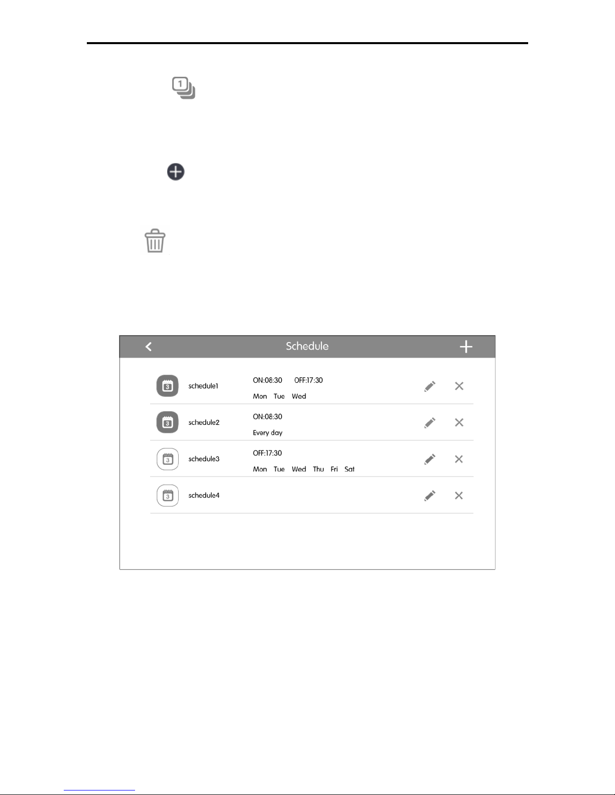
5.7 Schedule Management
Press Schedule button on the IDU home page to enter the page of schedule
management.
Fig.5.9 Schedule Home Page
(1) Open the schedule
Press the zone button to open or close the schedule.
When the icons and texts turn bule indicating the schedule is open.
When the icons and texts turn grey indicating the schedule is closed.
When schedule is open, centralized controller will send out the control order
automatically according to the time and parameters set by the schedule.
(2) Edit schedule
Page 30
Multi-VRF Centralized Controller
27
Press to enter the page of schedule editing.
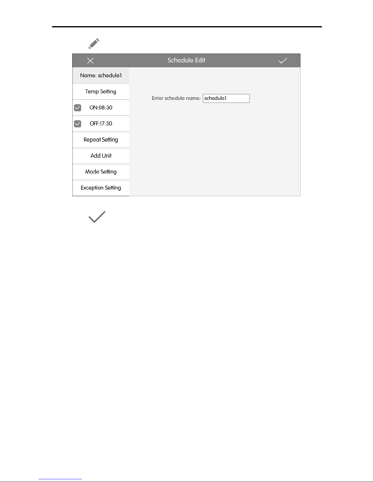
Fig.5.10 Page of Schedule Editing
Press to save the schedule setting.
1) Setting method of schedule control parameters is the same with that of the
single indoor unit control.
2) Add equipment
Press the “Add Unit” button to enter the page of equipment selection. User may
set the indoor unit that works according to the current schedule.
Note: For a same indoor unit, different schedules can be set at the same time.
In this case, unit will work according to the schedule setting that is previously
energized.
3) Repeat schedule
Press “Repeat Setting” button to enter the setting page. User can set the
schedule work repeatedly according to weeks.
4) Time setting
Press the “ON Time” or “OFF Time” button to enter the page of time setting.
User can set the time for unit to turn on/off automatically.
Note: The time to activate or stop unit can be set at the same time, but they
must not be the same.
5) Add exception
Press the “Exception Setting” button to enter the setting page of schedule
Page 31

Multi-VRF Centralized Controller
28
exception.
The calendar will pop in, user can select the date to activate or cancel
exception. Press to save the selected date.
Notes: When schedule exception has been set, air conditioner will not execute
the control order on the exception date set by the schedule.
User may add several exception dates.
(3) Add schedule
Press to add new schedules. Then the schedule editing page will pop in
for user to set relevant parameters.
Note: User may add up to 28 schedules.
(4) Delete schedule
Press to delete the selected schedule.
5.8 Local Setting
Press Setting on the home page to enter the setting page.
Fig.5.11 Setting Page
Press the “Local Setting” button to switch to the setting options of the current
unit.
Select the needed option at the left side column. Sliding up and down can turn
over the page.
Set the corresponding content at the right side.
Page 32

Multi-VRF Centralized Controller
29
Local setting includes:
(1) Sound, temperature unit, time format, mutual exclusion
Press the button to select one kind of setting.
(2) Language
Press the button can select system language, such as English,Simplified
Chinese or Traditional Chinese.
(3) Time setting
Set the date and time of the centralized controller system, can also set the
VRF unit time if needed.
(4) User password
Press the button can activate or inactivate user password.
When password is activated, it can be set or changed in 4~10 numbers or
characters. Original password is blank.
Press the button to save the password.
Note: If user password is activated, user needs to input password to enter the
control page when centralized controller is turned on or activated.
(5) Backlight setting
Pressing this button can set the timeout period of screen backlight. Screen will
be shut off and the centralized controller will enter sleep mode when the timeout
period is over.
Note: When centralized controller is in sleep mode, use can wake it up by
touching any part of the touch screen or the touch button at the right bottom of the
screen.
(6) Brightness
Pressing or dragging the sliding bar can adjust the backlight degree.
(7) Customer Service
User can set the name and phone number of the local customer service center
for the convenience of acquiring immediate solutions and technical support.
Press the
button to save the setting.
(8) Restore default settings
Press the “Reset” button to restore local setting, e-Control setting, group setting,
schedule setting, names and icons of indoor units, and other relevant ex-factory
default settings.
Page 33
Multi-VRF Centralized Controller
30
1) When switching between indoor network and outdoor network, or reset
unit IP, restore the ex-factory setting for centralized controller.
2) After debugging for the centralized controller is finished, connect in to the
network. If connect the centralized controller to the network during
debugging process, it needs to restore the defaulted ex-factory setting.
(9) View Selecting
Press“View Selecting”,Choose Room View or Device View.
5.9 Engineering Setting
On the home page, press setting to enter into setting interface.
Press the “Project Setting” button to switch to engineering setting, the operation
method is the same as the setting of this unit.
(1) Indoor unit register
Enter into the indoor unit register interface, select the chosen indoor unit
according to the displayed engineering No. of indoor unit icon, and then press
to save, it will display the registered indoor unit in the home page.
Notes: There are 32 sets of indoor units can be registered at most.
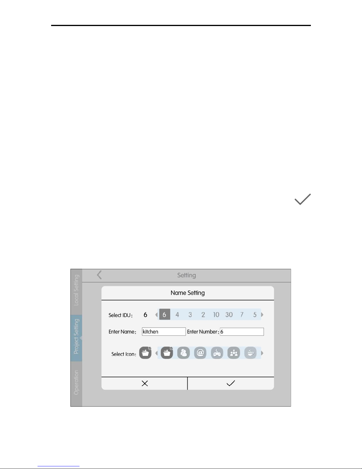
(2) Name&Icon setting
Switch to name&Icon setting interface to select the engineering No., and set
the name and icon of indoor unit.
Fig. 5.12 Setting Page of Indoor Unit
Press the Engineering No. to select the required indoor unit that needs to be
Page 34
Multi-VRF Centralized Controller
31
set.
(1)Name: can input number or letter (it should not be over 10 letters)
(2)Icon: press to select the preset icon.
(3)Engineering No.: it can be set to be 1-255.
(4)Press button to successfully save the setting. Then the indoor unit list
in the home page will display the new name and icon of indoor units.
5.10 Operation Notice
Press Setting on the homepage to enter the setting page.
Press the “Operation” button to switch to operation notice. The operation
method is the same with that of the local setting.
On the page of operation notice, user can view the information of the local unit,
customer service information, operation instructions and other notices.
6 Room View
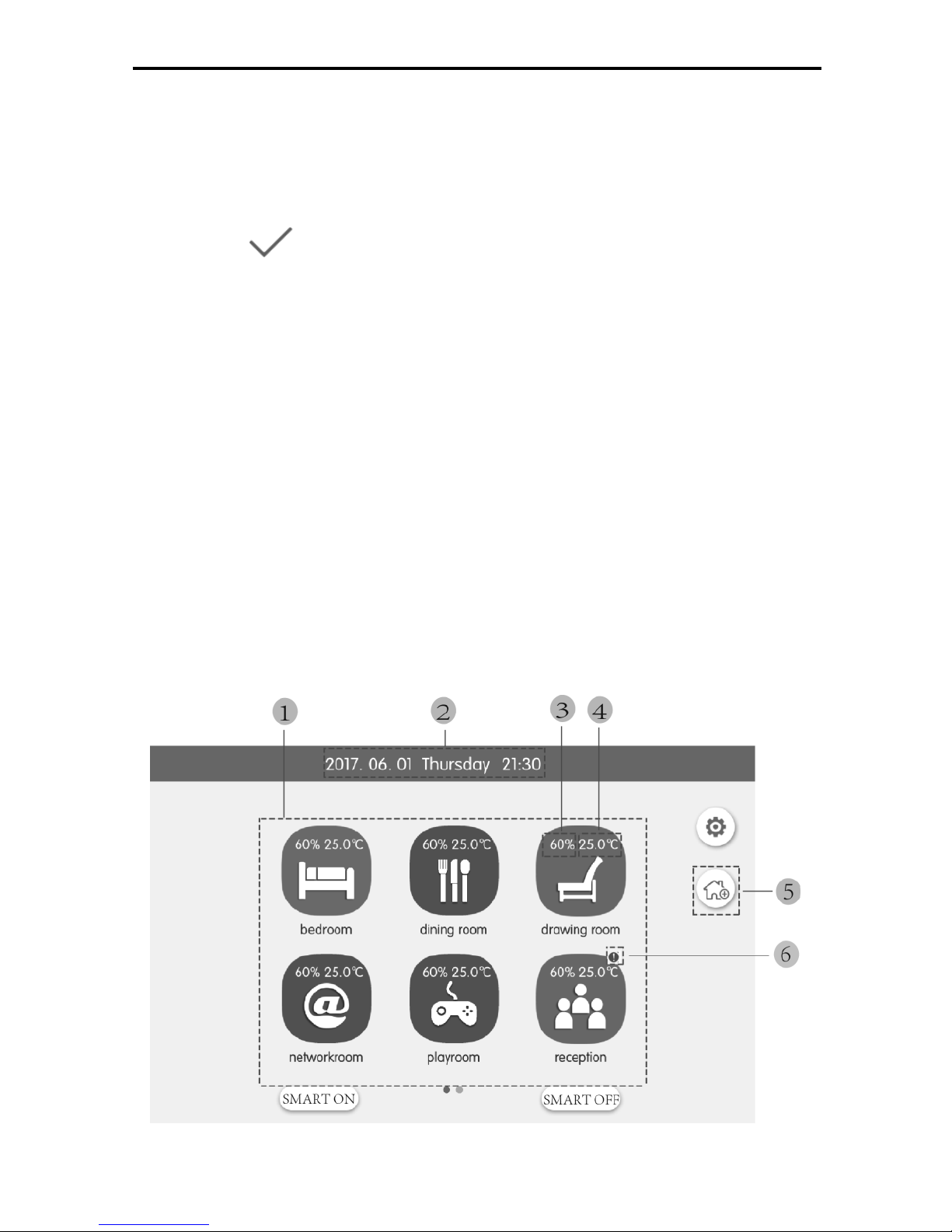
On homepage, click Setting-》Local setting -》View selection. Select room view
and then enter room view homepage.
Note: Room View function provides from version V2.2.0.
Fig. 6.1 Display Diagram of Room View Homepage
Page 35
Multi-VRF Centralized Controller
32
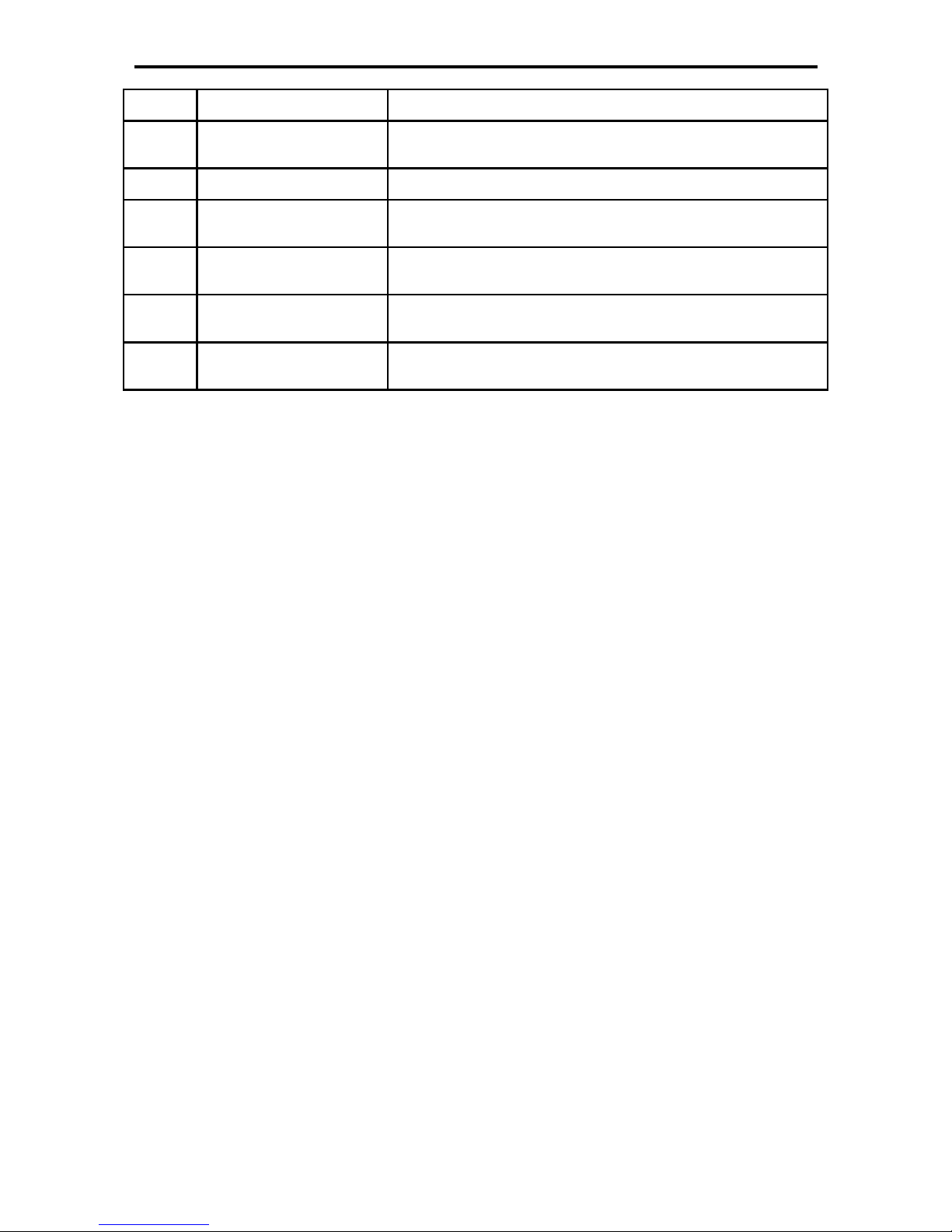
No.
Name
Instruction
1
Room selection
zone
Click it to enter room control interface
2
Time display zone
Display current system date, week and time
3
Room set humidity
icon
It is displayed when room smart switch is turned
on, which indicates room set humidity
4
Room set
temperature icon
It is displayed when room smart switch is turned
on, which indicates room set temperature
5
Room adding
button
Click this button to add rooms
6
Rooom Device
Error Icon
Error icon will be displayed if at least one
indoor unit is malfunctioning in the room.
6.1 All ON/OFF
Under room view homepage, press “SMART ON” button to turn on the smart
switches of all rooms. Press “SMART OFF” button to turn off the smart switches
of all rooms.
Note: When smart switch is turned off, indoor unit and fresh air keep original
state.
6.2 Room Control
On room view homepage, click room icon to enter room control interface.
Press room icon for 5 seconds to pop up the room name, icon and room device
selection settings.
Press “Room adding button” to add rooms. rooms quantity limit 16.
Page 36
Multi-VRF Centralized Controller
33
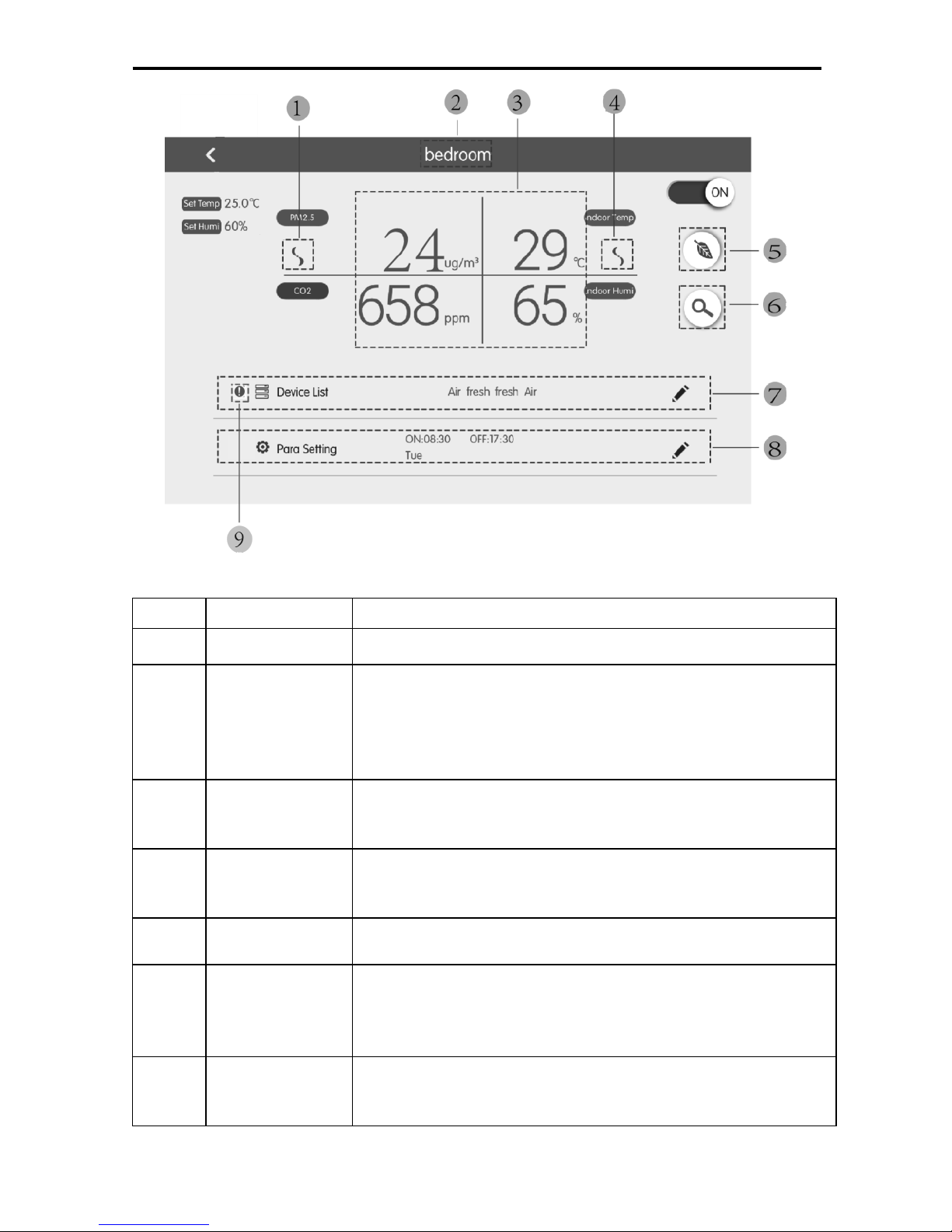
Fig. 6.2 Display Diagram of Room Control Interface
No
Name
Instruction
1
Curve view
Display the air state curve of the room in 24 hours
2
Energy-saving
strategy
button
Click this button to turn on or turn off energy-saving
strategy
Bright icon means energy-saving strategy is turned
on; extinct icon means energy-saving strategy is
turned off
3
Fan speed
icon of fresh
air unit
Display the fan speed of fresh air unit
4
Fan speed
icon of air
conditioner
Display the fan speed of air conditioner
5
Room name
zone
Display current room name
6
Air parameter
display zone
Display current PM2.5, CO2, indoor temperature and
indoor humidity,
Note: Only the fresh air unit which is connected with air
box can display the above values.
7
Device list
zone
Display device name of this room
Click Edit button to enter device selection interface
and select indoor unit
Page 37
Multi-VRF Centralized Controller
34
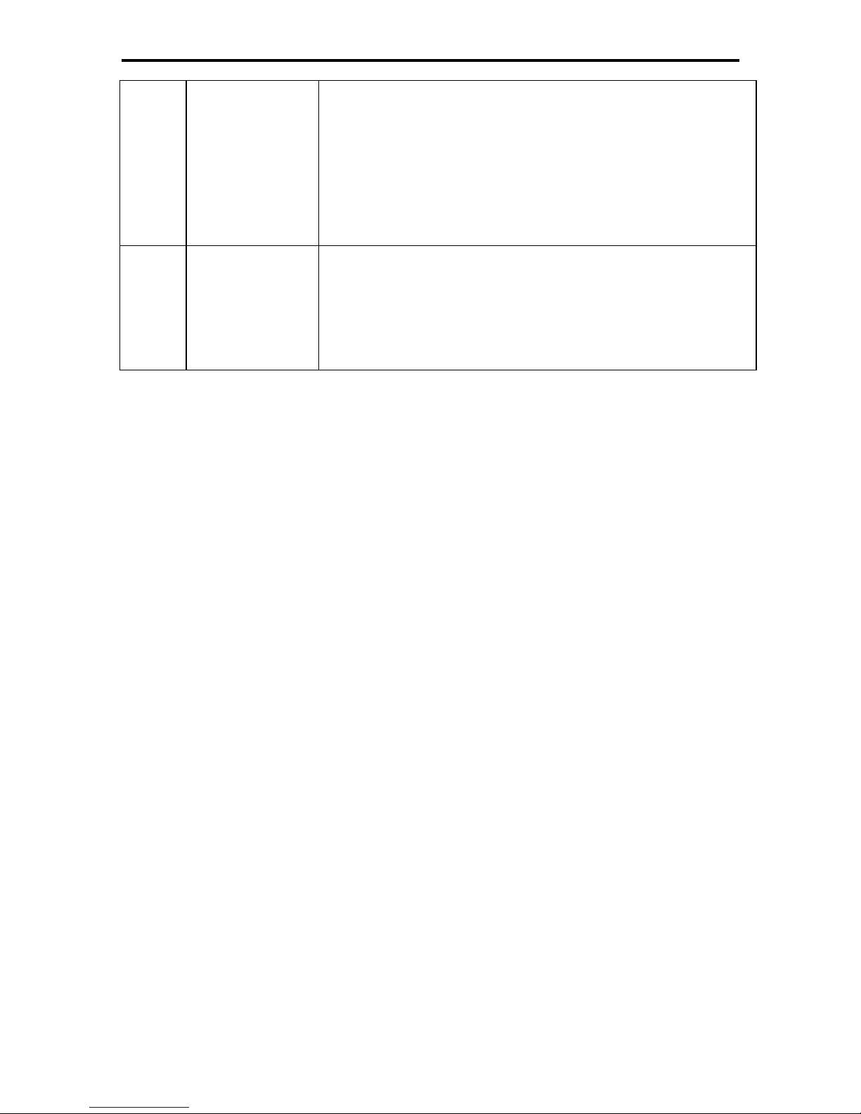
8
Parameter
setting zone
Display timer information of this room
Click Edit button to enter parameter setting interface
and then you can set the timer function of smart
switch in this room
Click Edit button to enter parameter setting interface
and then you can set the temperature, humidity,
fresh air fan speed and air conditioner fan speed in
this room
9
Rooom
Device Error
Icon
Error icon will be displayed if at least one indoor unit
is malfunctioning in the room.
6.2.1 Smart Switch
Click On/Off button to turn on or turn off the smart switch of this room.
When smart switch is turned on,it will turn on indoor unit and fresh air. it will
send target temperature, humidity and fan speed to indoor unit. It will intelligently
send specific mode to indoor unit according to indoor and outdoor temperature and
set target temperature.
When smart switch is turned off, indoor unit and fresh air keep original state.
6.2.2 Room Energy-saving Strategy
Click energy-saving strategy button to turn on or turn off energy-saving strategy
of this room.
When there are air conditioner and fresh air unit in the room, if smart switch
and energy-saving strategy are turned on, it will intelligently send startup, stoppage
and mode to the fresh air unit according to the operation status of air conditioner in
the room, indoor and outdoor temperature and set target temperature.
When smart switch and energy-saving strategy are turned on, backstage will
arrange detection automatically in every hour. When smart switch and
energy-saving strategy are detected to be turned on, it will smartly resend specific
mode, startup and stoppage to the fresh air unit according to the operation status of
air conditioner in the room, indoor and outdoor temperature and set target
temperature.
Note:
① When it is in energy-saving backstage detection, fresh air operation will be
Page 38
Multi-VRF Centralized Controller
35
valid after the detection. That is, when the status of fresh air unit is changed
by other ways, it will not be controlled by the energy-saving strategy any
more.
② The fresh air unit which is not connected with air box or the fresh air unit with
auto mode invalid are not controlled by smart switch and energy-saving
strategy.
6.2.3 Room Parameter Setting
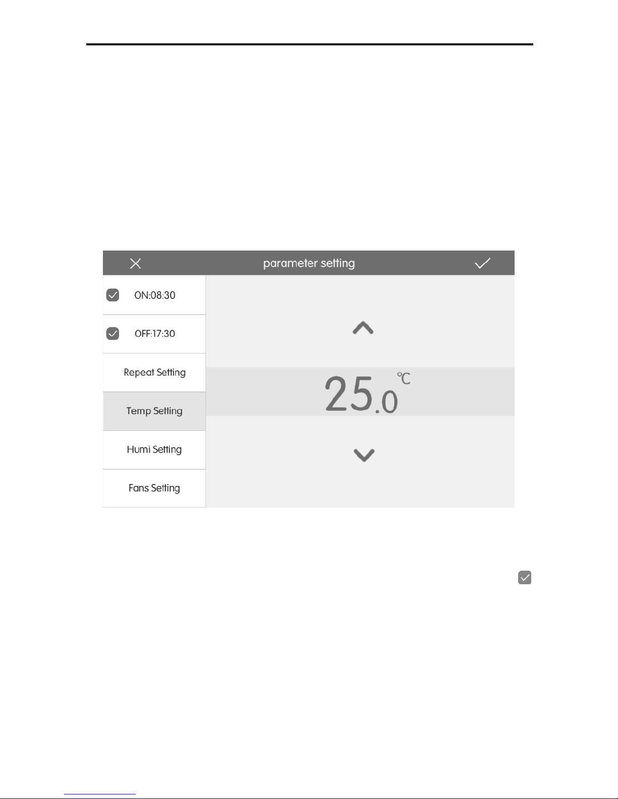
Click “Parameter setting” button to enter the setting interface of room
parameter.
Fig. 6.3 Diagram of Room Parameter Setting
1) Time setting
Click “Unit on time” or “Unit off time” button to enter time setting page.
You can set timer to turn on or turn off the smart switch in this room. Click
in front of the button to turn on unit on time or unit off time.
Note: Unit on time and unit off time can be set simultaneously. But the set time
shall be different.
2) Schedule repeat
Click “Repeat setting” button to enter setting page. You can set the schedule
repeat time according to week.
3) Temperature setting
Click “Temperature setting” button to enter temperature setting page. You
Page 39
Multi-VRF Centralized Controller
36
can set target temperature of the room.
4) Humidity setting
Click “Humidity setting” button to enter humidity setting page. You can set
target humidity of the room.
Note: Humidity setting is only available for the indoor unit with humidity
adjustment function.
5) Fan speed setting
Click “Fan speed setting” button to enter fan speed setting page. You can
set target fan speed of indoor unit and fresh air unit in this room.
6) Save setting
If smart switch is turned on, click button to send set target temperature,
target humidity and target fan speed immediately; mode command will be sent
intelligently according to indoor temperature, outdoor temperature and target
temperature. If smart switch is turned off, click button to save relevant
setting parameters.
6.2.4 Room Device List
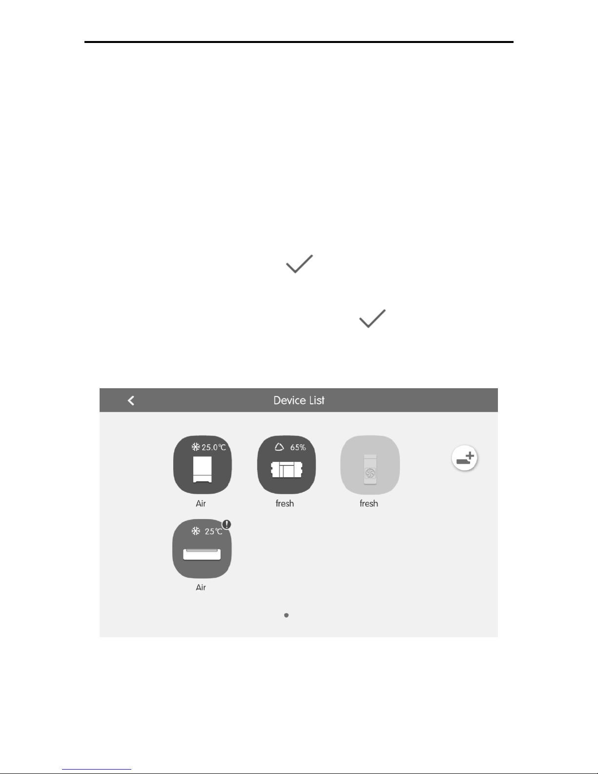
Fig. 6.4 Page of Room Device List
Click “Device list” button to enter device list interface of the room.
In device list interface, click indoor unit icon to enter single unit control.
Press indoor unit icon for 5 seconds to pop up indoor unit name, project
Page 40
Multi-VRF Centralized Controller
37
number and icon settings.
Click “Adding” button to add device or delete device in this room.
Note: When Adding devices , it only allows to add air condition units and
fresh air units which are connected with air box.
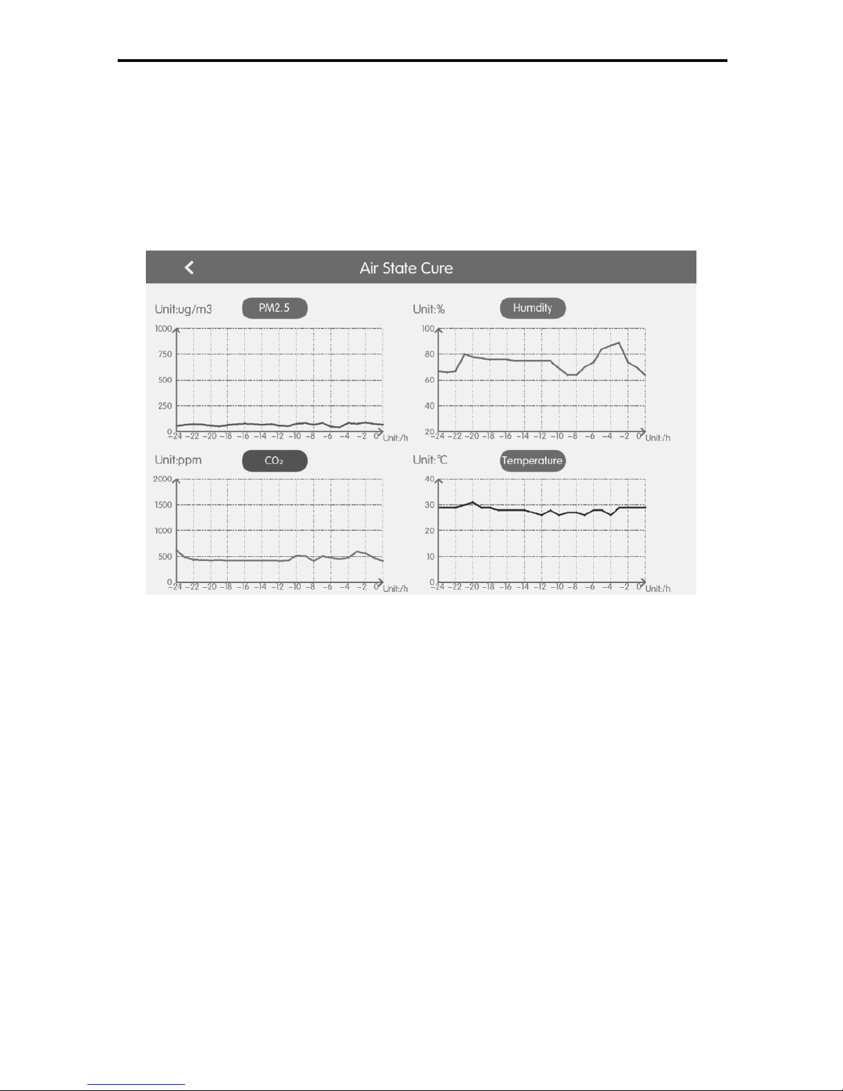
6.2.5 Air State Curve
Fig.6.5 Page of Air State Cure
Click curve view button to enter air state curve interface. This interface will display
the air state curve within 24 hours.
Note: Curve data sample will be taken every one hour. If the data sample in a
certain moment is 0, the point corresponding to this moment is cut off and this point
is discontiguous. This function is available only when the room adds the fresh air
unit which is connected with air box.
The PM2.5 range is:0-1000ug/m3 ;The CO2 range is:0-2000ppm ; The Temperature
range is:0--40℃ ; The Humidity range is: 20%-90%. if the parameter exceeds the
mileage, it wills display the maximum and minimum values.
Page 41

 Loading...