

Gree GWH18AC-D3DNA1B, GWH24AC-D3DNA1B, CB11500450, CB11500430, GWH18AC-D3DNA1B/I Service Manual
...
Service Manual
MODEL:
GWH18AC-D3DNA1B(CB11500430)
GWH24AC-D3DNA1B(CB11500450)
(Refrigerant R410A)
GREE ELECTRIC APPLIANCES INC.OF ZHUHAI

Table of Contents
Summary and features..................................................................................1
Part 1 Safety Precautions
Part 2 Specifications
.....................................................................................................3
Part 3 Construction Views
3.1 Indoor Unit .............................................................................................................5
3.2 Outdoor Unit ..........................................................................................................6
..........................................................................................2
........................................................................................5
Part 4 Refrigerant System Diagram
Part 5 Schematic Diagram
5.1 Electrical Data........................................................................................................8
5.2 Electrical Wiring......................................................................................................8
5.3 Printed Circuit Board..............................................................................................10
Part 6 Function and Control
........................................................................................8
....................................................................................12
.....................................................................7
6.1 Unit Display Panels ...............................................................................................12
6.2 Remote Control Display.........................................................................................12
6.3 Remote Control Operations .................................................................................13
6.4 Control System......................................................................................................17
Part 7 Installation Manual
7.1 Notices for Installation............................................
7.2 Installation Drawing..............................................................................................23
7.3 Install Indoor Unit ................................................................................................24
7.4 Install Outdoor Unit....................................................
7.5 Start-up ...............................................................................................................28
Part 8
Exploded Views and Parts List
8.1 Indoor Unit................................................................................
8.2 Outdoor Unit..............................................................
.........................................................................................21
.........................................
......................................
.............................................................29
..........................
........................................
......21
.....25
..29
...33

Table of Contents
Part 9 Troubleshooting
9.1 Troubleshooting ...................................................................................................37
9.2 Diagnostic Charts.................................................................................................38
9.2.2 Blinking LED of Indoor/Outdoor Unit .................................................................45
9.2.3 Check Maifunction Process ...............................................................................49
...............................................................................................37
Part10 Removal Procedure
10.1
Removal Procedure of Indoor Unit
10.2 Removal Procedure of Outdoor Unit (18K Unit)..................................................61
10.3 Removal Procedure of Outdoor Unit (24K Unit)..................................................64
.......................................................................................58
.....................................................................58
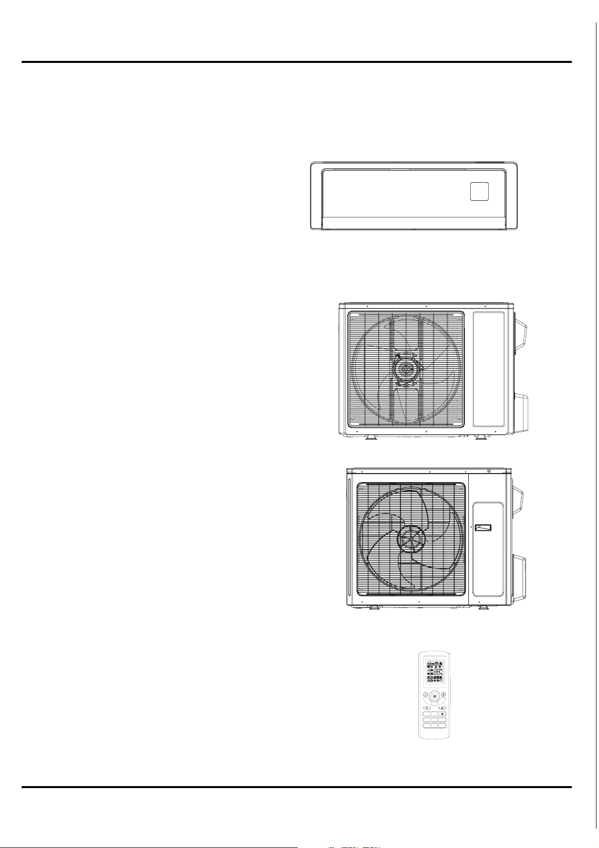
Summary and features
Indoor Unit
GWH18AC-D3DNA1B/I
GWH24AC-D3DNA1B/I
Outdoor Unit
GWH18AC-D3DNA1B/O
Summary and features
GWH24AC-D3DNA1B/O
Remote Control
YT1FF
FAN
IFEEL
TIMER
CLOCK
ON
X-FAN TEMP
TURBO SLEEP LIGHT
MODE
TIMER
OFF
1
1.Safety Precautions
Installing, starting up, and servicing air--conditioning equipment
can be hazardous due to system pressures, electrical components,
and equipment location (roofs, elevated structures, etc.).
Only trained, qualified installers and service mechanics should
install, start--up, and service this equipment.
Untrained personnel can perform basic maintenance functions such
as cleaning coils. All other operations should be performed by
trained service personnel.
When working on the equipment, observe precautions in the
literature and on tags, stickers, and labels attached to the
equipment.
Follow all safety codes. Wear safety glasses and work gloves. Keep
quenching cloth and fire extinguisher nearby when brazing. Use
care in handling, rigging, and setting bulky equipment.
Read these instructions thoroughly and follow all warnings or
cautions included in literature and attached to the unit. Consult
local building codes and current editions of the National Electrical
Code ( NEC ).
Recognize safety information. This is the safety--alert symbol
When you see this symbol on the unit and in instructions or
manuals, be alert to the potential for personal injury.Understand
these signal words: DANGER, WARNING, and CAUTION.
These words are used with the safety--alert symbol. DANGER
identifies the most serious hazards which will result in severe
personal injury or death. WARNING signifies hazards which
could result in personal injury or death. CAUTION is used to
identify unsafe practices which may result in minor personal injury
or product and property damage. NOTE is used to highlight
suggestions which will result in enhanced installation, reliability, or
operation.
Safety Precautions
The unit should be installed according to the instructions
in order to minimize the risk of damage from earthquakes,
hurricanes or strong winds.
Contact of refrigerant and fire generates poisonous gas.
Use specified refrigerant only.
!
CAUTION
UNIT DAMAGE HAZARD
Failure to follow this caution may result in equipment
damage or improper operation.
Never use the system compressor as a vacuum pump.
Refrigerant and indoor coil should be evacuated using the
!
!
.
recommended deep vacuum method of 500 microns. The alternate
triple evacuation method may be used if the procedure outlined
below is followed. Always break a vacuum with dry nitrogen.
Keep your fingers and clothing away from any moving parts.
Clear the site after installation. Make sure no foreign objects
are left in the unit.
Always ensure effective grounding for the unit.
lines
!
ELECTRICAL SHOCK HAZARD
Failure to follow this warning could result in personal injury
or death.
Before installing, modifying, or servicing system, main
electrical disconnect switch must be in the OFF position.
There may be more than 1 disconnect switch. Lock out and
tag switch with a suitable warning label.
Highly dangerous electrical voltages are used in this
system. Carefully refer to the wiring diagram and these
instructions when wiring. Improper connections inad-
equate grounding can cause accidental injury or death.
Ground the unit local electrical codes.
Connect all wiring tightly. Loose wiring may cause over-
heating at connection points and a possible fire hazard.
Make sure the ceiling/wall is strong enough to hold the
unit’s weight. The outdoor unit be installed in a
location where air and noise emitted by the unit will not
disturb the neighbors
Properly insulate any
inside a room to prevent
water
The outdoor unit must be installed on stable, level surface,
where there is no accumulation of snow, leaves
damage to
and
WARNING
according to
should
.
refrigerant or condensate line
"sweating" that can cause dripping
walls and floors.
or
running
or rubbish.
Caution
Never on the place where a combustible gas might
install
leak
, or it may lead to fire or explosion.
When the unit is installed at telecommunication centers or
hospitals, take a proper provision against noise.
When installing at a watery place, provide an electric leak
ground fault breaker
Do not wash the unit with water.
Be very careful about unit transportation.The unit not
be carried by only one person if it is more than 45lb
Do not touch the heat exchanger fins w th
Do not touch the compressor or refrigerant piping whithout
wearing glove
Do not operate the air conditioner without
Should any emergency occur, stop the unit and disconnect the
power immediately.
.
should
.
bare hands.
i
.
air filter
.
2

Specifications
2.Specifications
Model GWH18AC-D3DNA1B
Product Code CB11500430
Functi on
Rated Voltage 208-230V~
Frequency(Hz) 60Hz
Total Capacity (W) Standard (Low~High):
Total Capacity (Btu/h) Standard (Low~High):
Power Input (W) Standard (Low~High):
Rated Input (W)
Rated Current (A)
Air Flow Volume (
Moisture Removal
EER
(
BTU
Energy Class
)
/W
Model of Indoor Unit
Fan Motor Speed (r (H/M/L)
Output of Fan Motor (w)
Input Power of Heater (w)
Fan Motor Capacitor (μF)
Fa n Mo to r R LA(A)
Fan Type
CFM)
gal./hr.)
(
(SH/H/M/L)
pm)
COOLING HEATING COOLING HEATING
5275
1820~6450
˄
18000
6200~22000
˄
1500
180~2650
˄
2650 2700 2660 2700
SEER=20
˅
˅
˅
12 12.4 12.2 12.5
488/441/383/324
12
GWH18AC-D3DNA1B/I
1500/1150/1050/950 1380/1000/900/750
Cross flow fan
1200~7325
˄
25000
4100~25000
˄
240~2700
˄
0.5 0.7
HSPF=10.2 HSPF=10.2
20
/
1.5
0.25
7325
2700
˅ ˄
˅ ˄
˅ ˄
GWH24AC-D3DNA1B
CB11500450
208-230V~
60Hz
6155
2300~7680
21000
7800~26200
1750
220~2660
SEER=
˅ ˄
˅ ˄
˅
606/471/412/353
12
18
GWH24AC-D3DNA1B/I
35
2.5
0.45
Cross flow fan
1750~8200
6000~28000
260~2700
˄
/
7620
˅
26000
˅
2700
˅
Indoor
unit
Evaporator
Row-Fin Gap( )
Swing Motor Model
Output of Swing Motor (W)
Fuse (A)
Sound Pressure Level dB (A) (H/M/L)
Sound Power Level dB (A) (H/M/L)
Dimension (W/H/D)
Dimension of Package (L/W/H)
Net Weight /Gross Weight
inch
(inch)
(inch)
(lb.)
Aluminum fin-copper tube
2-
1/14 1/14
MP2 8VB
2.5
PCB 3.15A
46/43/40/35
56/53/50/45
37.7*11.8*7.7 42.9*12.9*8.2
40.7*15*11
28/39 35/46
Aluminum fin-copper tube
2-
MP3 5XX
2.5
PCB 3.15A
51/43/40/35
61/53/50/45
45.6*16.1*12.2
3
Specifications
Outdoor
unit
Model of Outdoor Unit
Compressor Manufacturer/trademark
Compressor Model
Compressor Type
L.R.A. (A)
Compressor RLA(A)
Compressor Power Input(W)
Overload Protector
Throttling Method
Starting Method
Working Temp Range
cooling/heating
(Fahrenheit)
Condenser
Rows-Fin Gap(
inch)
Coil length (l) x height (H) x coil width
(inch)
Fan Motor Speed (rpm) (H/M/L)
Output of Fan Motor (W)
Fan Motor RLA(A)
Fan Motor Capacitor (uF)
Air Flow Volume of Outdoor Unit
(CFM)
Fan Type
GWH18AC-D3DNA1B/O
China Resources (Shenyang) Sanyo
CO.,LTD
C-6RZ146H1A
Twin rotary compressor
41
8.4
1640
1NT11L-3979
Electronic e
xpand valve
Transducer starting
41
115
İTİİ
Aluminum fin-copper tube
1/16 1/16
2-
(L)
(32-15/16)*26*(1-1/2)
690/500
60
0.4
/
1883 2472
Axial fan
GWH24AC-D3DNA1B/O
China Resources (Shenyang) Sanyo
Twin rotary compressor
Electronic e
58
6
İİ
T
41
T
Aluminum fin-copper tube
(38-1/16)*(29-7/16)*(1-1/2)
CO.,LTD
C-6RZ146H1A
41
8.4
1640
1NT11L-3979
xpand valve
Transducer starting
115 5 8
İİ
6
İ
T
2-
780
90
0.6
/
Axial fan
Defrosting Method
Climate Type
Isolation
Moisture Protection
Permissible Excessive Operating
Pressure for the Discharge Side(
psi)
Auto defrost
T1
I
IP24
551
Permissible Excessive Operating
)
(W/H/D)
(lb.)
(oz.)
)
lb./ft.
(ft.)
psi
(inch)
ft.)
(inch)
(inch)
54
64
35*27.5*13.4 36.2*31.1*14.5
40.5*28.9*18.1
110/121
R410A/
51.1
25 25
0.14
Φ
1/4 1/4
1/2
Φ
50
100
Pressure for the Suction Side(
Sound Pressure Level dB (A)
Sound Power Level dB (A)
)
Dimension (W/H/D
(inch)
Dimension of Package
Net Weight /Gross Weight
Refrigerant and Charge
Precharge line length (
ft.
Gas additional charge( )
o
Connecti
n
P
ipe
Outer Diameter
Max Distance
The above data is subject to change without notice. Please refer to the nameplate of the unit.
Liquid Pipe
Gas Pipe
Height
Length (
Auto defrost
T1
I
IP24
551
174174
56
66
41.9*33*19
118/132
R410A/
63.4
0.22
Φ
Φ
5/8
50
100
4
Constrction views
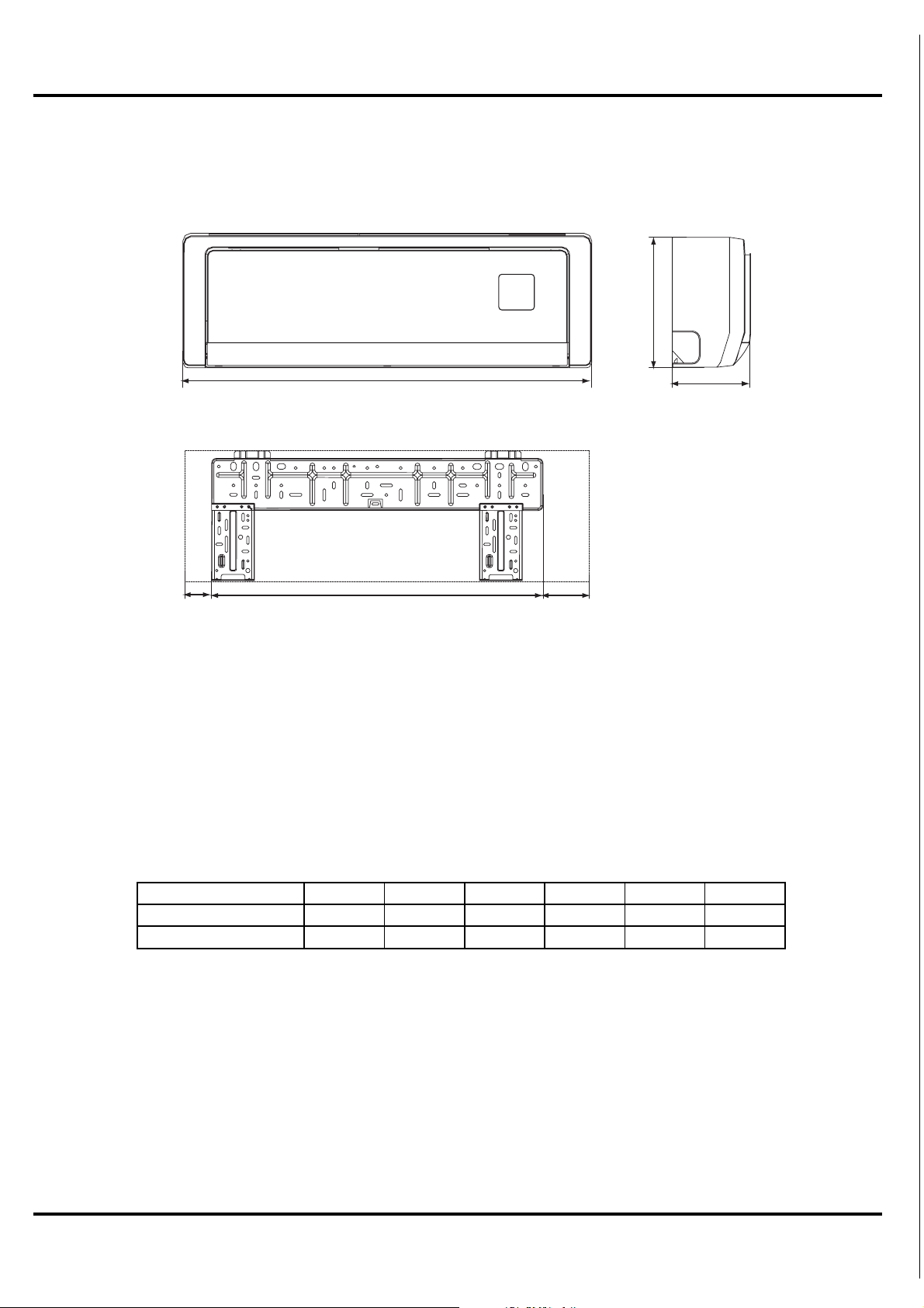
3. Construction Views
3.1 Indoor Unit
H
W
Q
RS
D
Model W H D Q R S
GWH18AC-D3DNA1B
GWH24AC-D3DNA1B
37-13/16
42-15/16
11-13/16
13
5
7-11/16
8-3/16
4-5/8
8-7/16
27-5/16
26-15/16
Unit:inch
5-13/16
7-1/2
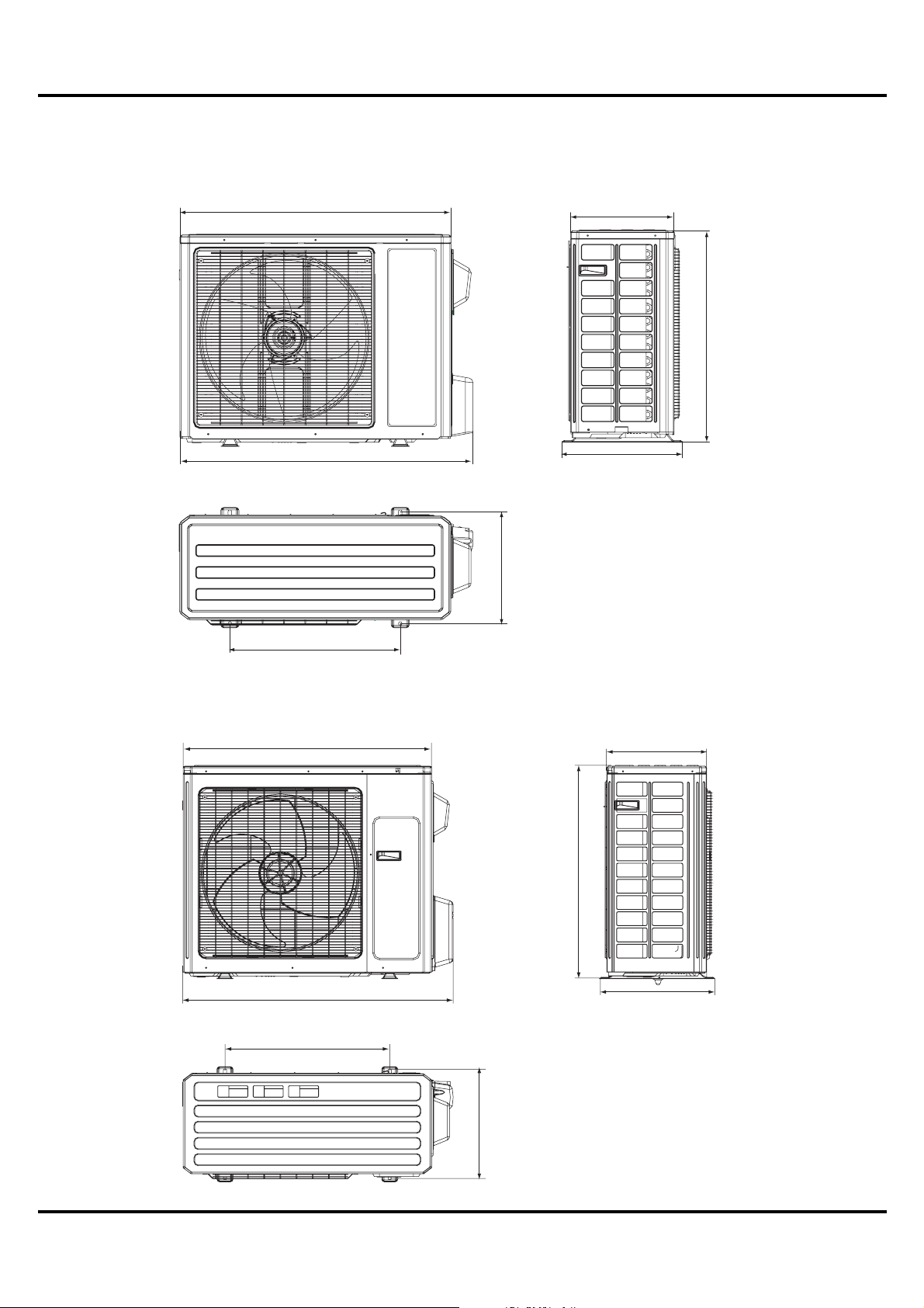
3.2 Outdoor Unit
GWH18AC-D3DNA1B/O
Constrction views
35-1/16
37-15/16
13-3/8
27-9/16
15-5/8
14-1/2
GWH24AC-D3DNA1B/O
22-1/16
36-1/4
39-3/8
24
14-9/16
31-1/8
16-13/16
Unit:(inch)
6
15-11/16
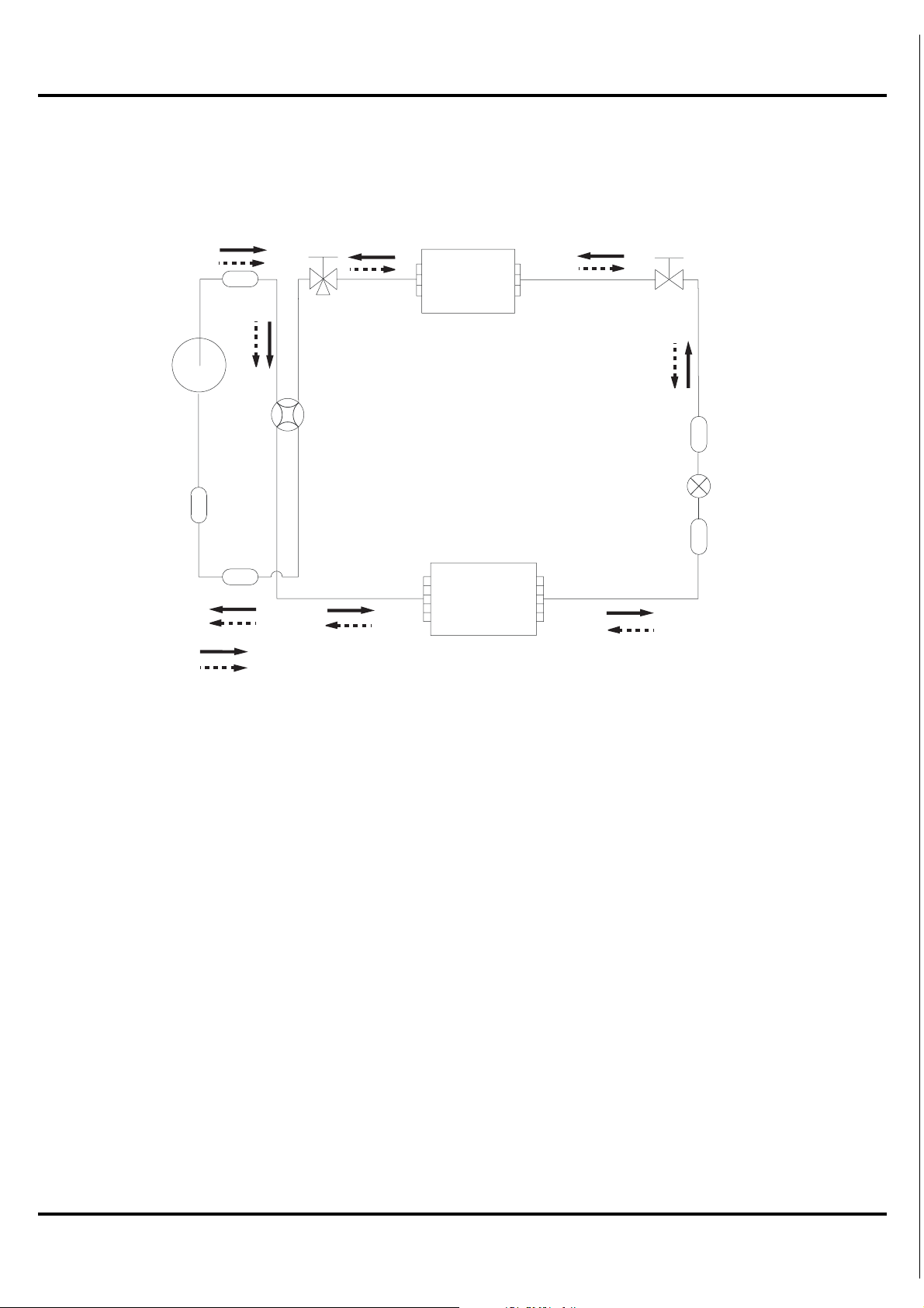
Refrigerant System Diagram
4. Refrigerant System Diagram
3-Way
valve
Muffler
rosserpmoC
4-Way valve
rotalumucca-buS
Strainer
Cooling
Heating
Heat exchanger
( INDOOR )
Heat exchanger
( OUTDOOR )
2-Way
valve
Strainer
Expansion valve
Strainer
Refrigerant pipe diameter
18K Unit
Liquid : 1/4" (6 mm)
Gas : 1/2" (12 mm)
24K Unit
Liquid : 1/4" (6 mm)
Gas : 5/8" (16 mm)
7
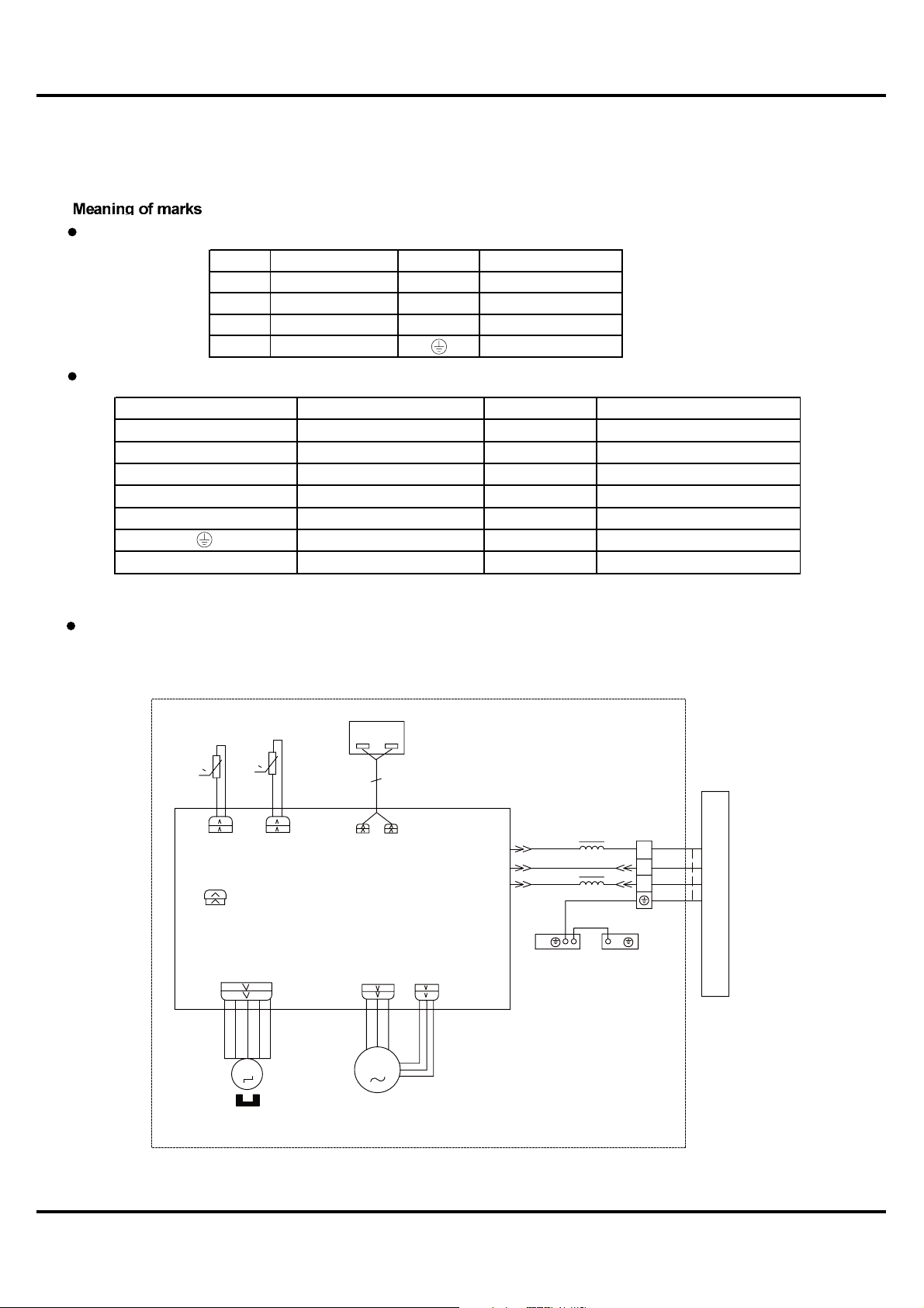
5. Schematic Diagram
Schematic Diagram
5.1 Electrical
Data
Indoor Unit
Symbol Color symbol Symbol Color symbol
WH
YE
RD
YEGN
Outdoor Unit
Symbol Parts name Symbol Color symbol
L1 L2 WH
YK
EKV RD
SAT
COMP
L YEGN
5.2 Electrical wiring
WH ITE
YELLOW
RED
YELL OW GREEN
REACTOR
Four-way-Valve
ELECTRONIC EXPANSION VALVE
OVERLOAD
COMPRESSOR
GROUNDING
REACTOR
BN
BU
BK
BROWN
BLUE
BLACK
GROUNDING
YE
BN
BU
BK
WH ITE
YELLOW
RED
SAT OVERLOAD BN BROWN
BLUE
BLACK
YELLOW GREEN
Indoor Unit
Models GWH18AC-D3DNA1B/I GWH24AC-D3DNA1B/I
DISPLAY
DISP1
AP1
AP2
DISP2
PG
M1
TEM.SENSOR
0
RT2
TUBE
CAP
JUMP
TEM.SENSOR
0
RT1
PRINTED CIRCUIT BOARD
SWING-UD
M2
ROOMTUBE
ROOM
PGF
N
COM-OUT
AC-L
1BU
2BK
3BN
4YEGN
PE
EVAPORATOR
5YEGN
PE
ELECTRIC BOX
XT
N(1)
2
3
OUTDOOR UNIT
SWING
MOTOR
8
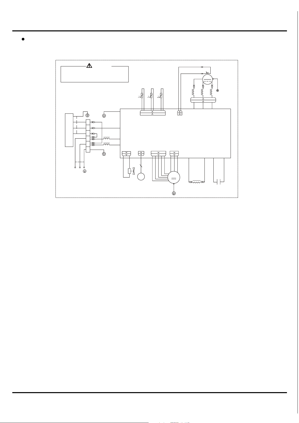
Schematic Diagram
Outdoor Unit
Models GWH18AC-D3DNA1B/O GWH24AC-D3DNA1B/O
L2
WARNING
PE
7BU
N(1)
2
8BN
3
L1
L2
20YEGN
G
XT
PE
14YEGN
11BK
9BN
10BU
PE
PE
COM-INNER
AC-L
N
Please don't touch any terminal when the
voltage of terminal P(DC+) and N(DC-) at
AP1 is higher than 30V to prevent the risk
of electrical shock!
INDOOR UNIT
L1
POWER
OUTTUBE
TEM.SENSOR
RT1
0
FA
4V
4YV
EKV
OUTROOM
TEM.SENSOR
RT2
T-SENSOR
RT3
0
HALL
EXHAUST
TEM.SENSOR
0
FAN MOTOR
OVC-COMP
AP1
OFAN
M
YEGN
PE
15YE
COMP-U
INDC1
12WH
1YE
4WH
5WH
2BU
16BU
INDC2
13OG
L
SAT
E
6YEGN
R
COMP
S
C(T)
PFCC1
18YE
PE
X1
PFCC2
C2
3RD
17RD
COMP-V COMP-W
19YE
These circuit diagrams are subject to change without notice, please refer to the one supplied with the unit.
9
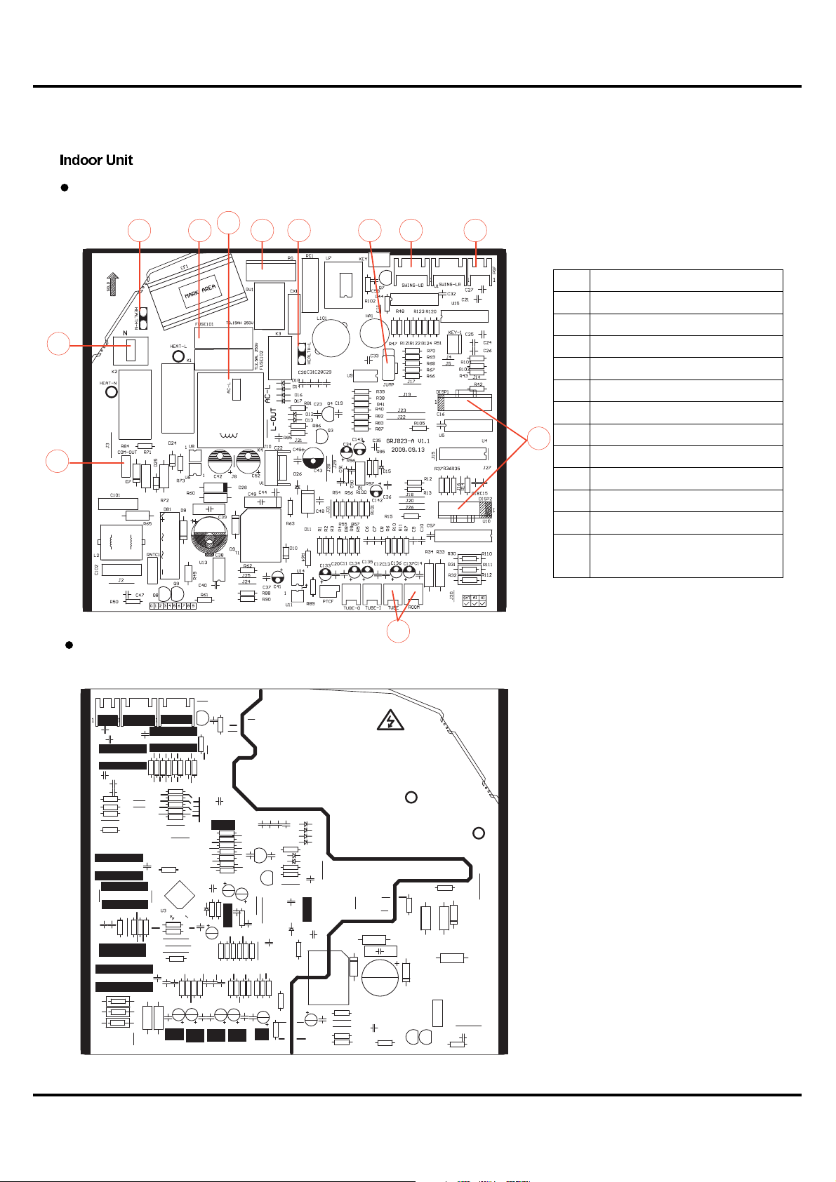
5.3 Printed Circuit Board
TOP VIEW
Schematic Diagram
1
12
BOTTOM VIEW
2345
6
89
7
No. Port Name
1 Neutral line
2 Neutral line of health function
3 Fuse
4 Live line
5 Power cable of PG motor
6 Live line of health function
7 Jumper cap
11
8 Link to up-down swing motor
9 Feedback line of PG motor
10 Temperature sensor
11 Display port
12 Port of communication with
outdoor unit
10
10
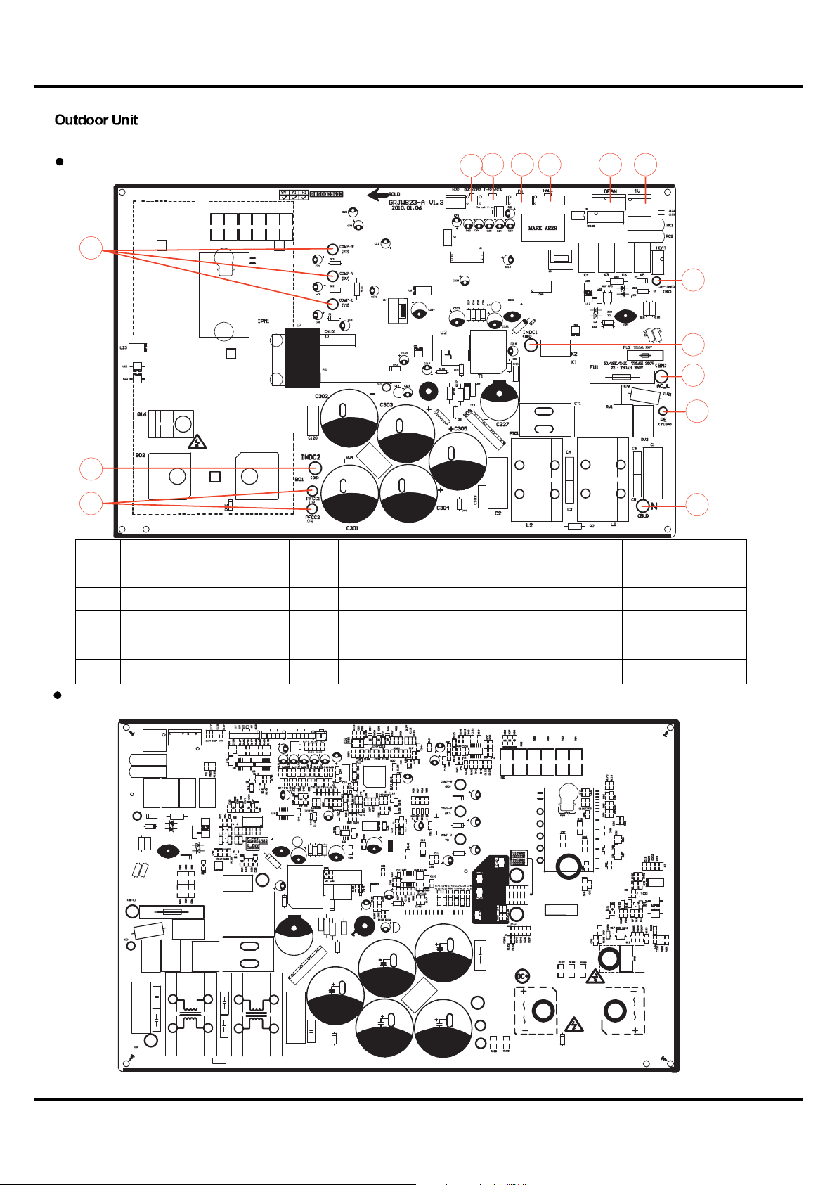
Schematic Diagram
TOP VIEW
2
76543
1
8
12
9
10
14
13
No. Port Name No. Port Name No. Port Name
1 Compressor port 2 Compressor overload protector 3 Temperature sensor
11
4 Electronic expansion valve 5 Fan HALL port 6 Outdoor fan
7 4-way valve 8 Port of communication with indoor unit 9 Live line
10 Grounding 11 Neutral line 12 Reactor port 1
13 PFC capacitor port 14 Reactor port 2 15
BOTTOM VIEW
11
6.Function and Control
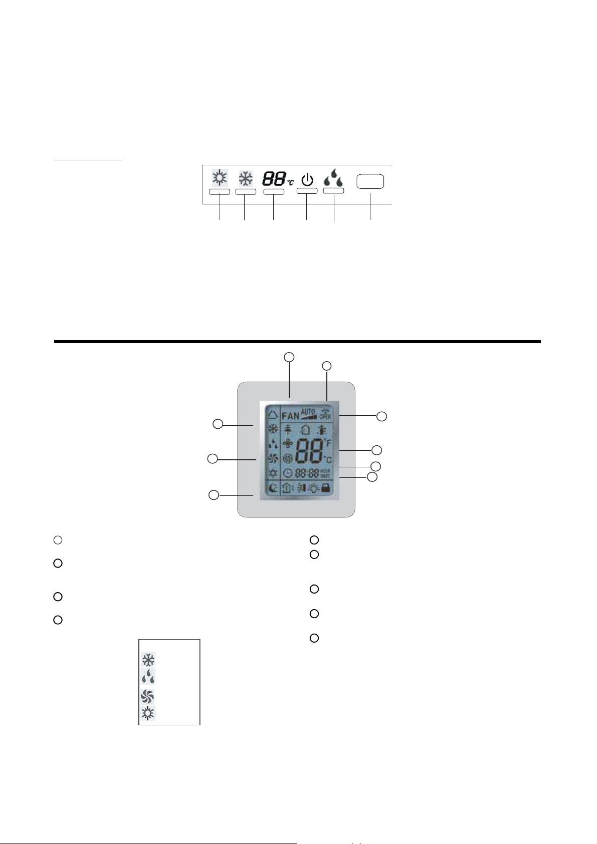
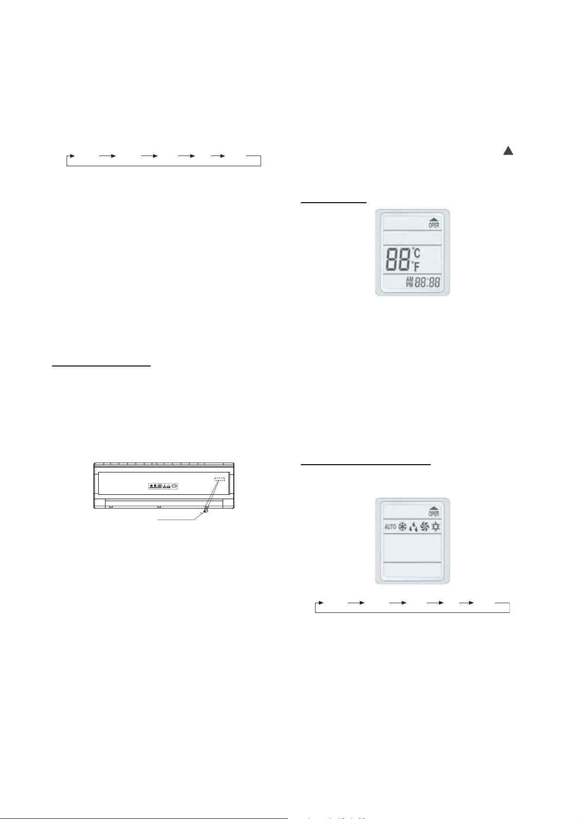
6.1 Unit Display Panels
NOTE: The display panel on the indoor unit can be turned on or off using the remote control . Press the SWING button twice to
turn the display on and off. Some of the functions will appear on the display panel, on the remote control, or both.
On the Unit:
RUN
INFRARED
SIGNAL
RECEPTOR
HEAT INDICATOR
TEMPERATURE*
COOL INDICATOR
DEHUMIDIFY MODE
* The temperature readout will be replaced by an error code if there is a malfunction.
6.2 Remote Control Display
4
6
5
1
TRANSMISSION INDICATOR: Illuminates when remote
control transmits signals to the indoor unit.
2
.ON/OFF INDICATOR: This symbol appears when the unit
is turned on by the remote control, and disappear when the
unit is turned off.
3
FAN SPEED DISPLAY: Indicates the set fan speed. AUTO
is displayed when unit is running in AUTO mode.
4
MODE DISPLAY: Indicates the current operation mode
“AUTO”, “COOL”, “DRY”, “FAN ONLY”, or “HEAT”
AUTO
AUTO Mode
COOL Mode
3
1
5
SLEEP DISPLAY: Indicates unit is running in SLEEP mode.
6
TEMPERATURE DISPLAY: Temperature setting from
61_F(16_C) to 86_F(30_C) will be displayed. If FAN mode
is selected, there will be no temperature displayed.
7
SWING DISPLAY: Indicates that louvers are moving
continuously for better air distribution.
8
CLOCK DISPLAY: Indicates the current time (0 to 24
hours).
9
TIMER DISPLAY: Indicates that time ON, time OFF, or
both is set.
A08297
2
6
8
9
A08295
DRY Mode
FAN Mode
HEAT Mode
A08296
NOTE: Symbols shown in this manual are for the purpose of demonstration. During actual operation, only the relevant symbols are
displayed.
12
6.3 Remote Control Operations
!
CAUTION
EQUIPMENT DAMAGE HAZARD
Failure to follow this caution may result in equipment damage.
Handle the control with care and avoid getting the control wet.
IMPORTANT: The remote control can operate the unit from a
distance of up to 25 ft. (7.6 m) as long as there are no obstructions.
This is one way communication only (from remote control to fan
coil).
The remote control can perform the following basic functions:
S Turn the system ON and OFF
S Select operating mode
S Adjust room air temperature set point and fan speed
S Adjust airflow direction
Refer to the Remote Control Function section for detailed
description of all the capabilities of the remote control.
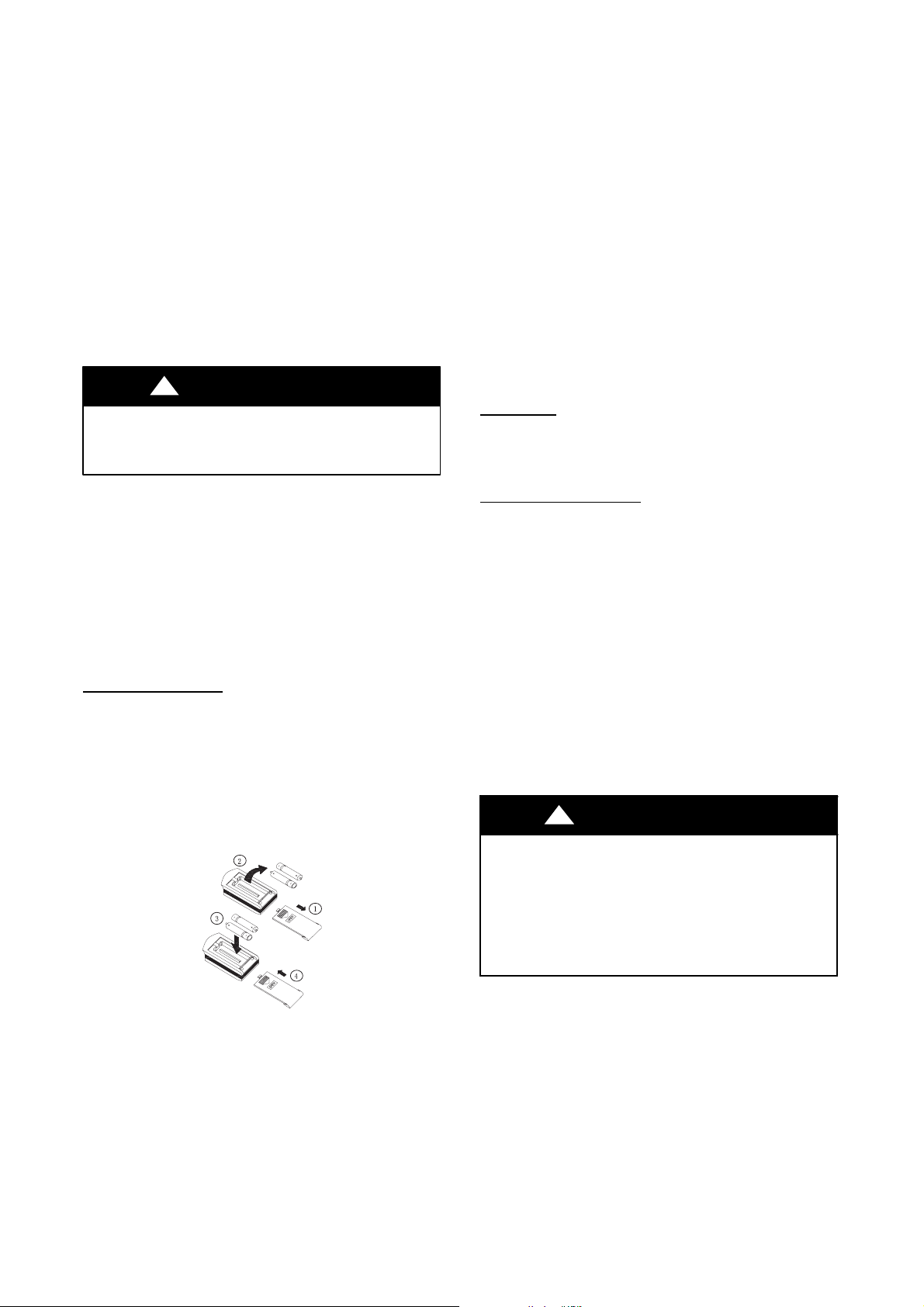
Battery Installation
Two AAA 1.5 v alkaline batteries (included) are required for
operation of the remote control.
To install or replace batteries :
1. Slide the back cover off the control to open the battery compartment.
2. Remove old batteries if you are replacing the batteries.
3. Insert batteries. Follow the polarity markings inside the
battery compartment.
4. Replace battery compartment cover.
4. Replace the batteries when there is no audible beep from the
indoor unit or if the Transmission Indicator fails to light.
Set the
Clock
Before you start operating the air conditioner, set the clock on the
remote control as outlined below. The clock panel on the remote
controller will display the time regardless of whether the air
conditioner is in use or not.
Initial Setting of the
After batteries are inserted in the remote control, the clock panel
will display ”12:00” AM.
1. Push the CLOCK button once
Clock:
S “AM” will flash
2. Push the “TIME +” or “TIME --” button. Each time you
press the button, the time moves forward or backward by
one minute depending on which button you press.
If you push the temperature button continuously, the time
adjusts in increments of 10 minutes.
3. When the right time is achieved, press the CLOCK button
once to set the time. The “AM” will stop flashing.
4. To readjust the Clock, Press the CLOCK button on the remote. The “AM” or “PM” will flash. Repeat steps 1
through 3.
NOTE: Note: The time of the CLOCK must be set before the
AUTO--TIMER function will operate.
!
CAUTION
UNIT OPERATION HAZARD
Failure to follow this caution may result in equipment
damage or improper operation.
A08299
NOTE:
1. When replacing batteries, do not use old batteries or a different
type battery. This may cause the remote control to malfunction.
2. If the remote is not going to be used for several weeks, remove
the batteries. Otherwise battery leakage may damage the remote
control.
3. The average battery life under normal use is about 6 months.
Static electricity or other factors (voltage fluctuations) can
cause the remote control clock to reset. If your remote
control is reset (the time of ”12:00” flashing), set the clock
before starting the unit.
13
Remote Control Operation -- Quick Start
NOTE: When transmitting a command from the remote control to
the unit, be sure to point the control toward the LED display on the
front panel of the unit. The unit will confirm receipt of a command
by sounding an audible beep.
1. Turn the unit on by pushing the ON/OFF button.
2. Select the desired mode by pushing the mode button.
AUTO
COOL
DRY
NOTE: Cool only units have no heat mode.
3. Select the temperature set point by pointing the control toward the unit and pressing the “TEMP +” or “TEMP --”
temperature set point buttons until the desired temperature
appears on screen.
4. Select the desired fan speed by pressing the FAN SPEED
button to select desired fan speed.
NOTE: If unit is operating in Dry mode, low fan speed will be
displayed and the fan speed cannot be changed.
5. Set the airflow direction. When the unit is turned on, the
louvers default to the cooling or heating position. The user
can adjust the default louver position by pushing the
“SWING” button. The louver will start to move. At this
point, the user can have the louver moving continuously or
stopped when the desired position is achieved by pushing
the “SWING” button.
Emergency Operation
If the remote control is lost, damaged, or the batteries are
exhausted, the AUTO button on the unit can be used to run the
unit.
Open the front cover panel and press the AUTO button once
briefly when the system is off.
To stop emergency operation, push the AUTO button once. The
emergency operation can also be stopped by pushing the
“ON/OFF”, “CLOCK”, “T--OFF”, or “T--ON” twice.
FAN
ONLY
HEAT
A08301
REMOTE CONTROL FUNCTIONS
The remote control is the interface between the user and the
high-- wall systems. Commands are entered by the user to control
the system. Any command that has been entered with the remote
control will remain in the memory until it is changed by the user
or the batteries are replaced.
NOTE: When entering commands, point the remote control in
the direction of the LED display on the front panel. The
will appear for a short period of time on the remote control
when the command is entered. The unit will only emit an
audible beep when the signals are received correctly.
On/Off Button
A08302
When the air conditioner is not in operation, the remote control
will display the last set point and time.
S Press the On/Off button to start the unit.
-- The unit will start in the last operating mode and set
point. The “OPER” indicator will appear. The “RUN”
indicator on the display panel turns green.
S Press button On/Off to stop the unit.
-- The “RUN” indicator light on the display panel will turn
red and the remote control will display the setpoint and
time. “OPER” will disappear.
NOTE: If the On/Off button is pressed too soon after a stop, the
compressor will not start for 3 minutes due to the inherent
protection against frequent compressor cycling.
Selecting an Operating Mode
Use the Mode button to select one of the available modes.
AUTO button
The following occurs when the AUTO button is pushed:
S 77_F(25_C) will be displayed on display panel.
S Unit will run in FAN ONL Y mode if return air temperat-
ure is between 68_F(20_C) and 77_F(25_C).
S Unit will run in HEATING if return air temperature is
less than 68_F.
S Unit will run in COOLING if return air temperature is
greater than 77_F(25_C).
S Fan speed will be set to AUTO
S SWING will be on.
A08300
AUTO
COOL
DRY
FAN
ONLY
HEAT
The selected mode will be displayed on the remote control and the
appropriate light will illuminate on the display panel. When the
unit is in AUTO, 77_F(25_C) will show on the display panel.
There is no icon for “FAN ONLY” on the display panel.
14
A08303 /A08301
Setting the Room Temperature Set Point
A
Pressing the “TEMP +” and “TEMP --” buttons will raise or lower
the temperature.
The unit will confirm signal receipt with a beep and the value of
the set temperature on the display, on the remote control, and on
the front panel, will change accordingly.
The temperature can be set between 61_F(16_C) and 86_F
(30_C).
NOTE: In Cooling mode, if the temperate selected is higher than
the room temperature, the unit will not start. The same applies for
the Heating mode if the selected temperature is lower than the
room temperature.
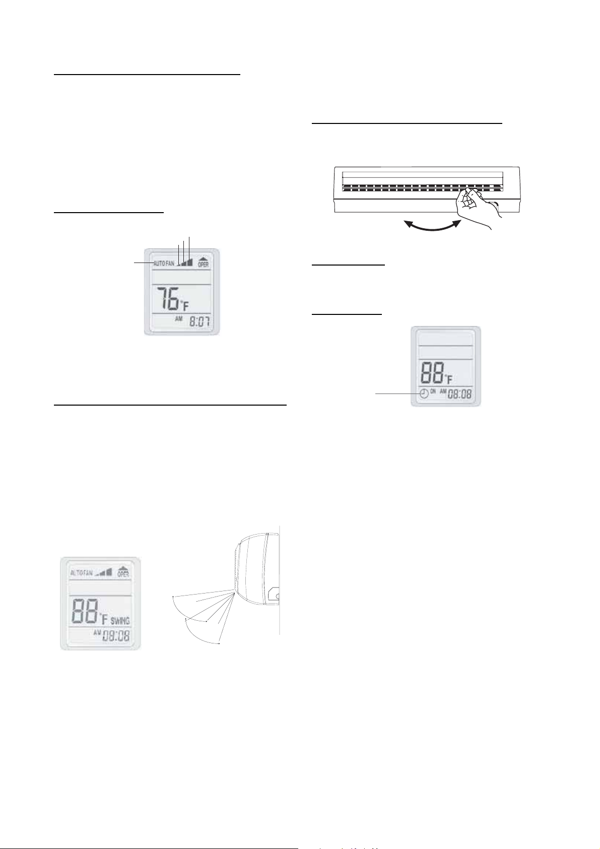
Selecting the Fan Speed
HIGH
MEDIUM
LOW
pushed, the louvers will not start moving right away. This is
due to the fact that the fan will not start running until the coil
temperature is warm enough to prevent discomfort to the user
by blowing cold air.
Selecting Vertical Direction of the Louver
The vertical louvers can be adjusted manually to direct the airflow
to achieve the optimal comfort in the space.
A07543
UTO
Timer Function
TIMER ON (to start the unit) and TIMER OFF (to stop the unit)
can be used separately or together. The clock on the remote control
must be set before using this function.
Timer ON on ly
A08304
The fan speed can be selected by pressing the “FAN” button.
NOTE: When the unit is on, the fan will run continuously in
cooling or heating. When in heating, there might be situations
where the fan will slow down or shut off to prevent cold blow.
Timer ON Indicator
Selecting the Horizontal Direction Louver Position
When the unit is turned on, the louvers default to the cooling or
heating position.
If the louver position is not providing adequate comfort due to
room layout or where people are gathered, the user has two
options:
1. Have the horizontal louvers move continuously. This is accomplished by pushing the “SWING” button. When this
button is pushed, the “SWING” icon will appear on the remote control and the louvers will operate in a preset range
as shown in the figure below.
This function will allow the unit to start automatically at the set
time. The TIMER ON can be set while the unit is on or off.
To set the TIMER ON function, perform the following:
1. Push the “T--ON” button once.
2. The timer indicator will appear on the remote control with
“ON” flashing.
3. Push the “TIME --” or “TIME +” until the desired on time
is reached.
NOTE: Pressing the “TIME --” or “TIME +” will decrease or
increase the time in 1 minute increments.
Pressing the “TIME --” or “TIME +” continuously will
decrease or increase the time in 10 minute increments.
4. Push the “T--ON” again. The “ON” icon will stop blinking
and the time at which the unit will start is set.
COOLING
The “T--ON” time will be stored in memory indefinitely until it is
cancelled by the user by pushing the “CANCEL” button or the
remote control batteries are replaced.
HEATING
If the unit is running and the “T-- ON” set time is reached, the unit
will continue operating normally.
A08307
NOTE: When the unit is shut off by the user using the
“ON/OFF” button, and if the “T-- ON” is set, the following will
2. If a stationary position other than the default position is preferred, push the “SWING” button once and allow the louver
to move to the desired position then push the “SWING”
button again.
NOTE: Always use the remote control to adjust the louver
position otherwise, abnormal operation may occur . If the
louver is manually adjusted out if its range, turn the unit off
and then on again.
Sometimes, in the heating mode, when the “SWING” button is
be displayed on the remote control.
-- Set Point
-- T i m e
-- “TIME ON” icon
On the display panel, the operation light will turn red.
When the “T --ON” is reached, the display on the remote does
not change, and the unit is running as indicated by the
operation light on the front cover turning green. To get display
on the remote, push the “ON/OFF” button once.
A08305
15
Timer OFF only
Timer OFF Indicator
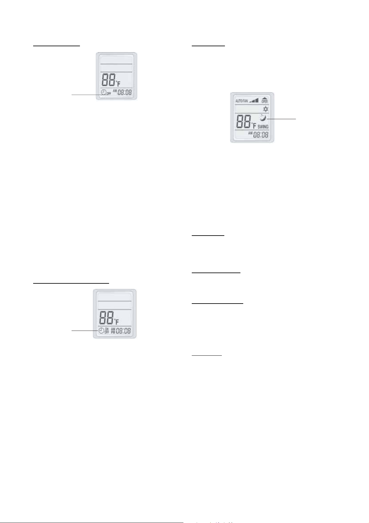
Sleep Mode
This mode is used to conserve energy and can be used when the
unit is in the COOL, HEAT or AUTO mode only.
Cool Mode
-- Push the SLEEP button. The SLEEP display will appear on
the remote control.
A08306
This function will allow the unit to stop automatically at the set
time. The timer can be set while the unit is on or while it is off.
To set the “TIMER OFF” function, perform the following:
1. Push the “T--OFF” button once.
2. The “TIMER” indicator will appear on the remote control
with “OFF” flashing.
3. Push the “TIME --” or “TIME +” button until the desired
ON time is reached.
NOTE: Pressing the “TIME --” or “TIME +” will decrease or
increase the time in 1 minute increments.
Pressing the “TIME --” or “TIME +” continuously, will
decrease or increase the time in 10 minute increments.
4. Push the “T-- OFF” button again, the “OFF” icon will stop
blinking and the time at which the unit will turn off is set.
The “T--OFF” time will be stored in memory indefinitely until is
is cancelled by pushing the the “CANCEL” button or the batteries
are replaced in the remote control.
If the unit is running and the “T--OFF” set time is reached, the unit
will turn off and the operation indicator light on the front panel will
turn red. The display on the remote control will remain the same
as when the unit was running. To turn the unit on again, push the
“ON/OFF” button twice. The operation indicator light on the front
panel will turn green.
Timer ON and Timer OFF
Timer Indicator
A08308
Use both functions as described in “TIMER ON” and “TIMER
OFF” sections to program the unit to turn on and shut off at
specified times. Times will be stored in memory until cancelled
by user or the remote control batteries are replaced.
Sleep Mode Icon
A08309
-- After 1 hour the set point will be raised by 1.8_F(1_C).
-- After another hour, the set point will be raised by another
1.8_F(1_C)andthefanwillruninlowspeed.
-- The SLEEP mode will be cancelled when the SLEEP button
is pushed again.
Heat Mode
-- Same as cooling mode but set points will be lowered by
1.8_F(1_C) and the HEAT icon will disappear from the
display panel.
Time Delay
If the On/Off button is pressed too soon after a stop, the
compressor will not start for 3 minutes due to the inherent
protection against frequent compressor cycling. The unit will only
emit an audible beep when the signals are received correctly.
Heating Features
If the unit is in the heating mode, there will be a delay when the
fan starts. The fan will start only after the coil is warmed up to
prevent cold blow.
Defrost Operation
In heating mode, if the outdoor coil is frosted, the indoor fan and
outdoor fan will turn off while system removes the frost on the
outdoor coil. “H1” will be displayed on the display panel on the
front cover of the unit.
The system will automatically revert to normal operation when
frost is removed from the outdoor unit, and “H1” will disappear.
Auto Start
If the power fails while the unit is operating, the unit stores the
operating condition, and it will start operation automatically under
those conditions when the power is restored.
16
CONTROL SYSTEM
The 53GXC(Q) units are equipped with microprocessors in the
indoor and outdoor units. They perform the following two
functions:
1. Provide safety for the system
2. Control the system and provide optimum levels of comfort
and efficiency.
3MinuteTimeDelay
In order to protect the compressor, there is a 3 minute delay on
break even if the control is calling for heating or cooling.
Indoor Coil Freeze Protection
When the unit is running in the COOL or DRY MODE, the indoor
coil can freeze due to any of the following:
S Low system charge
S Reduced indoor airflow
S Restricted refrigerant flow
S Low ambient temperature (outdoor)
S Low load (indoor)
The indoor coil thermistor monitors the coil temperature
continuously. Any time the coil temperature drops below 30.2_F
(--1_C), the compressor and the outdoor fan (30 seconds later) will
be switched off until the coil temperature rises above 42.8_F(6_C)
and the compressor was off for a minimum of 3 minutes.
Compressor
Outdoor Fan
Indoor Fan
30 S
≥3 min
Stop Compressor
Reduce Comp. Freq.
No Freq. Increase
208.4
217.4
230 ° F
A09347
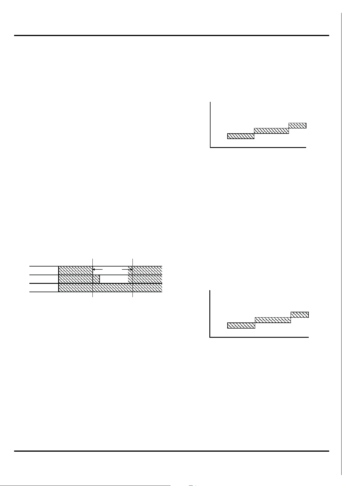
Fig. 15 – Compressor Gas Discharge Temperature Protection
When the compressor discharge temperature drops below 194F,
the unit will resume normal operations.
Low Voltage Protection
If the incoming voltage is below the minimum allowed, E5 will be
displayed on the front panel of the indoor unit.
Condenser High Temperature Protection
Condenser high temperature can occur due to any of the following
conditions:
S High outdoor ambient
S Outdoor fan blocked
S Outdoor coil blocked
The outdoor coil thermistor continuously monitors the temperature
and communicates with the microprocessor. Depending on the
temperature measured, the compressor will be allowed to increase
the frequency if needed to meet the load or is forced to run at the
current or reduced frequency. If the temperature gets excessively
high the compressor will be de--energized as shown below:
30.2 ° F
42.8° F
A09346
Fig. 14 – Coil Freeze Protection
High Compressor Discharge Temperature
The compressor discharge temperature can be high due to any of
the following:
S Low refrigerant charge
S Blocked capillary
The compressor discharge line thermistor continuously monitors
the temperature and communicates with the microprocessor.
Depending on the temperature measured, the compressor will be
allowed to increase the frequency to meet the load or is forced to
run the current or reduced frequency. If the temperature gets
excessively high, the compressor will be de--energized as shown
below:
Stop Compressor
Reduce Comp. Freq.
No Freq. Increase
133 136.4 143.6 ° F
A09348
Fig. 16 – High Temperature Protection
When the outdoor coil temperature drops to 123.8F, the unit will
resume normal operations.
NOTE: In heating the indoor fan is de--energized 60 seconds after
the compressor is de--energized.
17
Compressor Over Current Protection
Over current protection can result due to any of the following:
S The ambient temperature is too high
S Locked rotor on the compressor
S Blockage in the refrigeration circuit (capillary tubes for
example)
S Outdoor air is blocked or restricted
The compressor current is monitored continuously. Based on the
amp draw measured, the microprocessor will allow the compressor
to increase frequency, maintain frequency, drop frequency, and
eventually de--energized the compressor if excessive amps are
experienced.
12K9KCurrent
Frequency
Frequency
Compressor
Compressor
Outdoor Fan
Outdoor Fan
Indoor Fan
Indoor Fan
IIDI
I
IM
I
DIO
I
I
M
M
D
D
O
O
O
12K9KCurrent
76I
76I
87I
87I
98I
98I
109I
109I
A09349
Fig. 17 – Overcurrent Protection
IPM Module Protection
This can be caused by any of the following:
S Loss of cooling to the heat sink
S High ambient temperatures
S Low voltage
S Loose screws fastening the board to the heat sink
When this occurs, H5 is displayed on the LED display on the front
panel of the indoor unit.
SEQUENCE OF OPERATION
Interface
A wireless remote control, supplied with the unit, is the interface
between the fan coil and the user. The wireless remote control has
the following characteristics:
S Dedicated controllers for _Cor_F. Each indoor units
comes with two remotes that are clearly labeled for the
appropriate temperature scale.
S The remote control range is from 61_F (16.1_C)to 86_F
(30_C).
S The same remote is used for both cooling only and heat
pump units
S The wireless remote control range is 25 ft (7.6 m).
S The same remote can be used to control more than one
unit.
S If the remote control is lost, damaged, or the batteries are
exhausted, the system can be operated using the manual
button located under the front panel
MODES OF OPERATION
The units have five main operating modes:
1. Fan only
2. Cooling
3. Heating (heat pump only)
4. Auto
5. Dry (Dehumidification)
The units also have the manual mode that allows the unit to be
operated without the remote control.
Fan Only Mode
In this mode, the system circulates the room air without changing
the room air temperature.
Cooling Mode
In this mode, the system cools and dries the room air with the fan
running continuously, either at a selected fan speed or Auto fan
speed. The fan runs even when the compressor cycles off. This
feature enhances room comfort and efficiency of the system.
Compressor, Outdoor Fan Operations, and Indoor
Operation
As shown below, the compressor and outdoor fan motor cycle on
and off based on the conditions of the set point and the room
temperature. The indoor fan runs continuously.
T
T
+1.8 °F
amb≥TS
amb≥TS
+1.8 °F
T
T
+ 1.8°F
+ 1.8°F
S
S
T
T
TS-3.6°F
TS-3.6°F
Compressor
Outdoor Fan
Indoor Fan
T
T
-3.6°F
-3.6°F
amb≤TS
amb≤TS
S
S
≥ 3 min
≥ 3 min
30S 30S
30S 30S
Fig. 18 – Cooling Mode
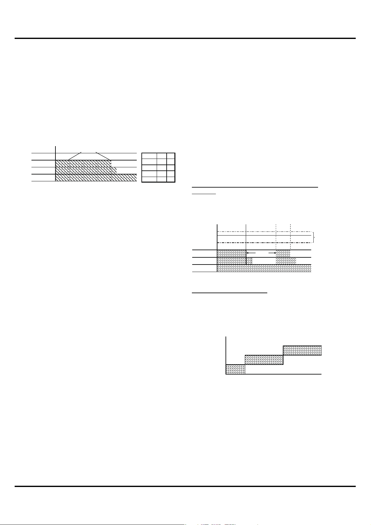
Indoor Fan Operation --
Cooling
When in cooling mode, the fan runs continuously either at the
chosen set speed, or in Auto mode, where the speed is determined
by the microprocessor based on the difference between the room
temperature and the temperature set point as shown below:
High
Medium
Low
T
S
S
TS + 3.6°FT
TS + 3.6°F
Fig. 19 – Auto Fan -- Cool Only Mode
fan
Compressor
matches load
A09249
A09250
18
 Loading...