

Gree 26TTW09HP115V1A, 26TTW09HC230V1A, 26TTW12AC115V1A, 26TTW09AC230V1A, 26TTW07HP230V1A Owner's Manual
...
TTW Air Conditioner
Thank you for choosing our product.
For proper operation, please read and keep this manual carefully.
26TTW09AC115V1A 26TTW09HP115V1A
26TTW12AC115V1A 26TTW09AC230V1A
26TTW09HC230V1A 26TTW07HP230V1A
26TTW09HP230V1A 26TTW12AC230V1A
26TTW12HC230V1A 26TTW12HP230V1A
Models
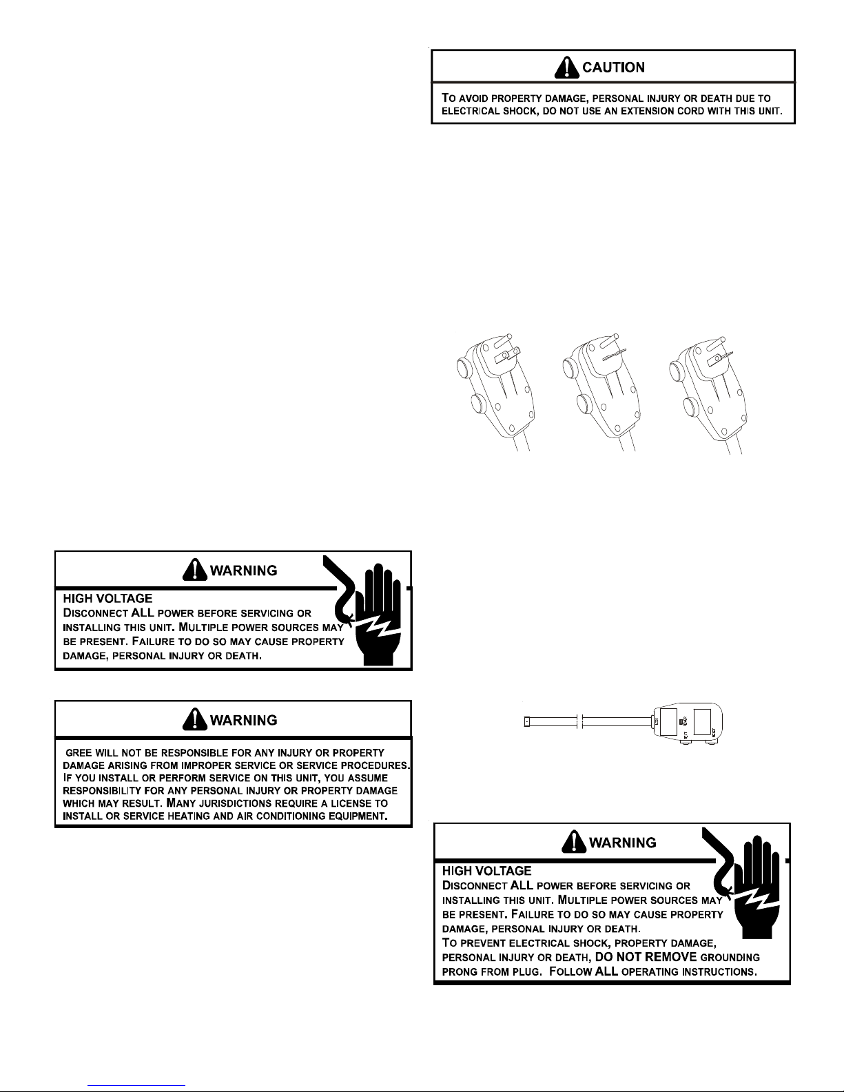
TABLE OF CONTENTS
Important Note to Homeowner................................................... 2
Important Note to Servicer .......................................................... 2
Operating Instructions ................................................................ 2
Unit Features .............................................................................. 2
Installation Instructions .............................................................. 3
Wiring.......................................................................................... 6
Air Conditioner Features ............................................................ 7
Remote Control .......................................................................... 7
Additional Information .............................................................. 13
Normal Operating Sounds and Conditions ............................. 13
Obtaining Service ..................................................................... 13
Product Warranty .......................................................................14
IMPORTANT NOTE TO THE HOMEOWNER
This manual is to be used by qualified, professionally trained HVAC
technicians only. Gree does not assume any responsibility
for property damage or personal injury for improper service procedures or services performed by an unqualified person.
IMPORTANT NOTE TO THE SERVICER
Read this manual and familiarize yourself with the specific items
which must be adhered to before attempting to service this unit.
The precautions listed in this Installation Manual are intended as
supplemental to existing practices. However, if there is a direct
conflict between existing practices and the content of this manual,
the precautions listed here take precedence.
UNIT FEATURES
This unit has many features which are different than those found
on conventional units. The servicer must be familiar with these
features in order to properly service the unit.
Check the data specification plate and ensure the proper voltage
and current rating is available for the type power plug on the unit.
DO NOT REMOVE THE GROUNDING PRONG FROM THE POWER
CORD. Note the types of acceptable plugs in Figure 1. Do not use
an extension cord for the installation of this product. Refer to the
data specification plate for electrical requirements.
120V
15 Amp
208/230V
15 Amp
Figure 1
208/230V
20 Amp
OPERATING INSTRUCTIONS
Check the data specification plate and ensure the proper voltage
and current rating is available for the type power plug on the unit.
DO NOT REMOVE THE GROUNDING PRONG FROM THE POWER
CORD. Note the types of acceptable plugs on the following figure.
Refer to the data specification plate for electrical requirements.
• LCDI or AFCI Power Cords - Underwriters Laboratories and
the National Electric Code (NEC) now require power cords
that sense current leakage and can open the electrical circuit to the unit on units rated at 250 volts or less. In the event
that unit does not operate, check the reset button located on
or near the head of the power cord as part of the normal
troubleshooting procedure.
LCDI Power Cord
Figure 2
2
VOLTAGE MEASUREMENTS
Before connecting the unit, measure the supply voltage. Voltage
must fall within the voltage utilization range given in the following
table.
Operating Voltage
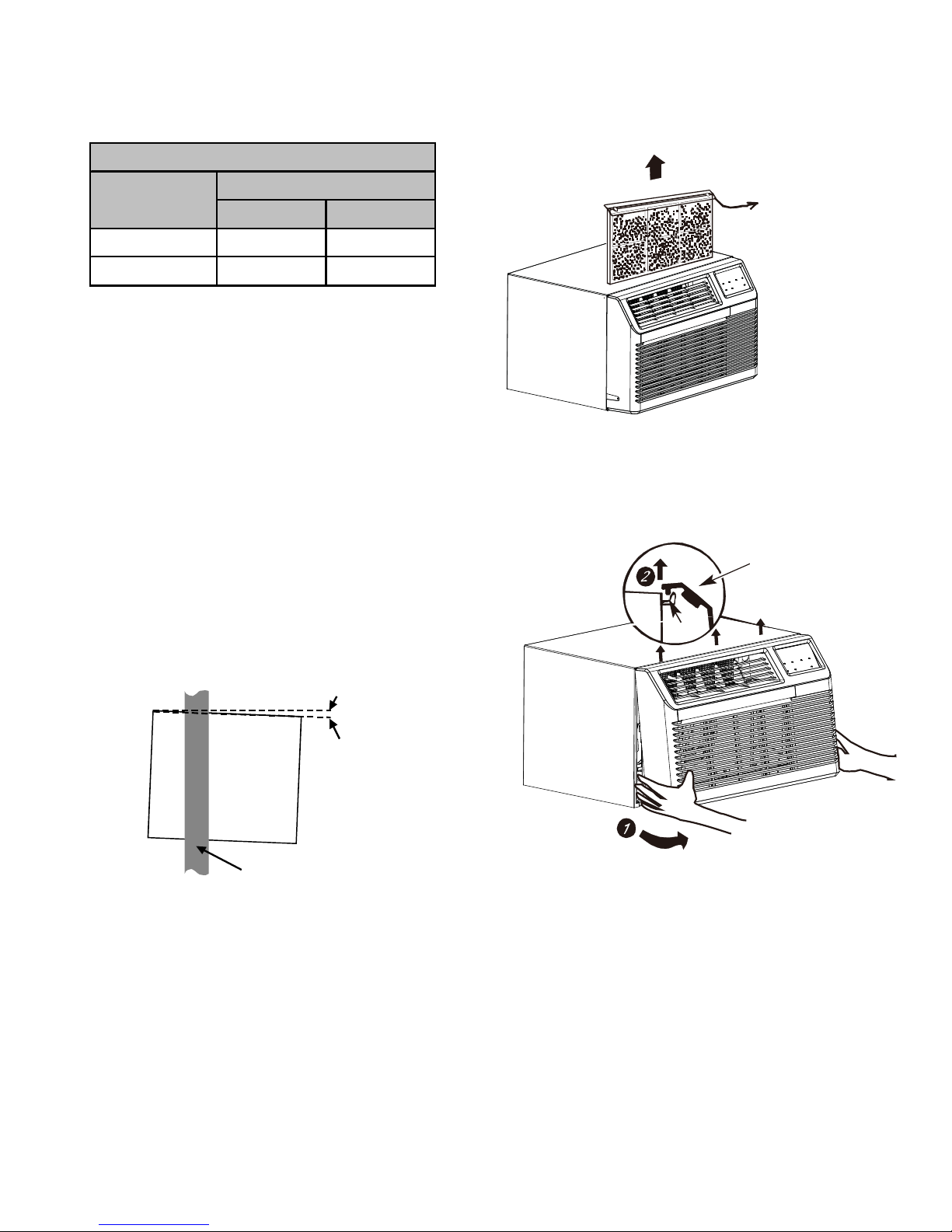
CHASSIS INST ALLATION
1. Remove front grille. See Figure A.
Unit Voltage
Voltage Uti li z atio n Ra ng e
Rating Minimum Maximum
230/280 187 253
115 103 126
INSTALLATION INSTRUCTIONS
To ensure that the unit operates safely and efficiently, it must be
installed, operated, and maintained according to these installation and operating instructions and all local codes and ordinances,
or, in their absence, with the latest edition of the National Electrical
Code. The proper installation of this unit is described in the following sections. Following the steps in the order presented should
ensure proper installation.
SLEEVE INST ALLA TION
In order for condensate water to drain properly inside the unit, the
sleeve must be installed properly:
• Level from right to left.
• A slight downward pitch from the indoor side to the outdoor
side as shown in Figure 3.
Refer to the Installation Instructions supplied with the wall sleeve
for a complete description of the installation procedure.
NOTE: Wall sleeve is not shipped with chassis and
must be purchased separately.
OutsideInside
Level
Lift up on
Filter Handle
Figure A
The front grille can be removed for more thorough cleaning or to
make the model and serial numbers accessible. To remove, pull
the filter out and remove the four grille screws.
Grille
Tab
Wall
Sleeve
Outside
Wall
Figure 3
1/4 Bubble
Tilt To
Outside
Pull the grille out from the bottom and lift up from the tabs on the
top of the case.
2. Remove the grounding screw and wire next to the grounding
symbol on right side of chassis control panel (Figure 3). Attach other end of ground wire to the hole in the bottom right
side of the sleeve with #8 x 3/8” blunt point sheet metal screw.
The hole on the sleeve is indicated by grounding symbol on
the sleeve. Slide chassis part of the way into the sleeve and
reattach the ground wire back to the hole on the right side on
the control panel area next to the grounding symbol.
3
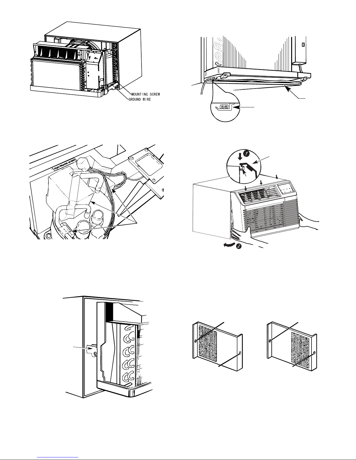
Figure 3
Tab
Grille
6. If outlet is on the left side of the unit, route power cord as
shown in Figure D.
Power
Clamp
Cord
3. Remove shipping pads inside air conditioner next to
compressor. (See Figure B.)
Remove
shipping
pads
Figure B
4. Carefully slide the chassis into the sleeve. Ensure that
the ground wire is not pinched or in the path of the
condenser fan.
5. Loosen locking plate screw and rotate tab with tab
behind wall case flange (See Figure C) then tighten
locking plate screw.
Figure D
To replace front grille:
Hook the tabs on the front grille even with the tabs on the case and
snap into place. Replace the screws and filter. Refer to Page 3,
Figure A.
VENT CONTROL AND AIR DIRECTION (See Figure E)
The vent control is located behind the front grille on the right
side of the air discharge area. When set at CLOSE only the air
inside the room will be circulated and conditioned. When set at
OPEN, some inside air is exhausted outside.
Locating
Hole
Locating
Hole
Locking
Plate
Figure C
4
Screw Hole
OPEN position
(Mesh end toward back)
Screw Hole
CLOSE position
(Mesh end toward front)
Figure E
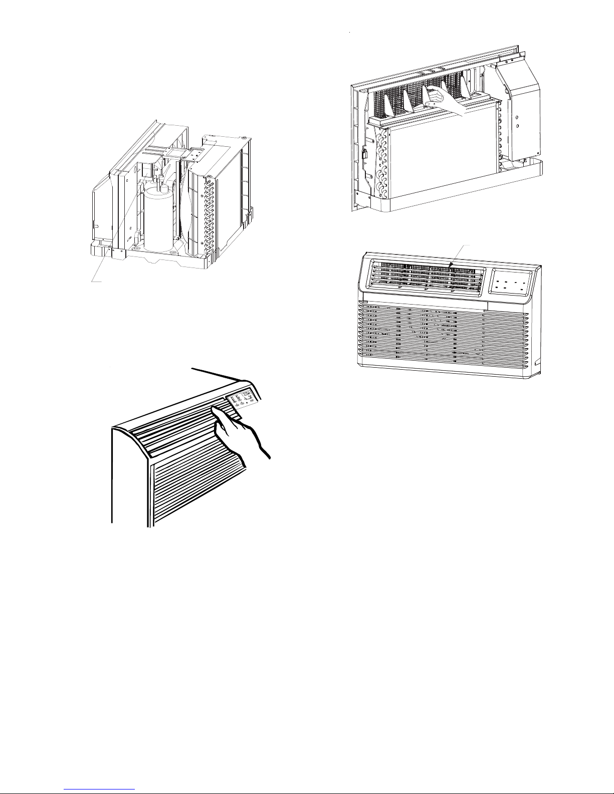
To open or close the vent:
DISCHARGE AIR GRILLE
1. Remove the front grille.
2. Remove the vent card screw.
3. Remove the vent card, turn it over and replace it by locating
rear hole in card over locating pin inside air discharge and
reattaching screw at front.
EXHAUST AIR VENT
Figure 4
AIR DIRECTION:
Horizontal louvers on the front grille let you control the air direction
up and down.
Remove the front grille to adjust the vertical louvers side-to-side
to direct the air left or right.
Figure 5
IMPORTANT NOTES:
1. The unit is equipped with a rubber-grommet-mounted
compressor. These grommets are factory set and require
no adjustment.
2. Obstruction to air flow must be checked and removed.
Check the indoor and outdoor grilles for obstructions. The
unit must be located where curtains, furniture, trees, or
other objects do not block air flow to and from the unit. If air
is obstructed and/or deflected back into the unit, the air
conditioner’s compressor may cycle on and off rapidly.
This could cause damage to the compressor.
5
 Loading...