

Page 1
Gree 2000 Technical Service Manual
Introduction
This technical manual describes large amount of information regarding Gree 2000 type air conditioner,
including pictures, technical parameters, explosive views, parts and components list and circuit diagrams etc.
Engineers, service staff and dealers of Gree hold that this is the most convenient way to know more about
the information of our product technology.
Technical Service Department, Gree Electric Appliances, Inc. Of Zhuhai
March, 2004
Table of Contents
1 Summary and features...........................................................................................................................1
2 Specifications and technical parameters...............................................................................................3
3 Part name ................................................................................................................................................4
4 Outline and installation dimension.....................................................................................................5-6
5 System schematic diagram.....................................................................................................................7
6 Electrical circuit diagram ......................................................................................................................7
7 Function manual and operation method of remote controller.......................................................8-21
9 Explosive view and parts and components list..............................................................................22-30
8 Disassembly procedures ..................................................................................................................31-34
10 Care and maintenance.....................................................................................................................35-36
11 Installation guide..............................................................................................................................37-42
12 Malfunction analysis........................................................................................................................43-45
Page 2
1
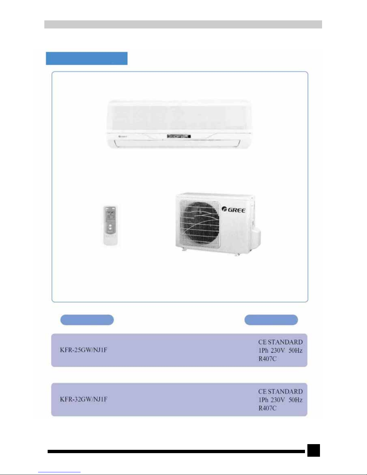
1. Summary and features
Models Remark
Page 3
3
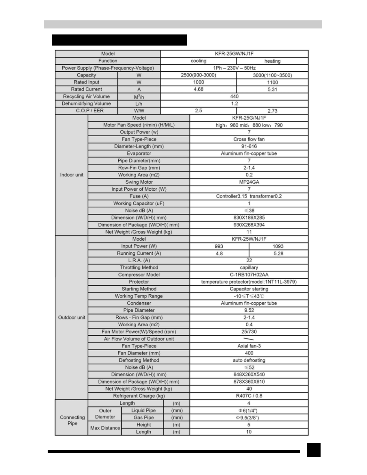
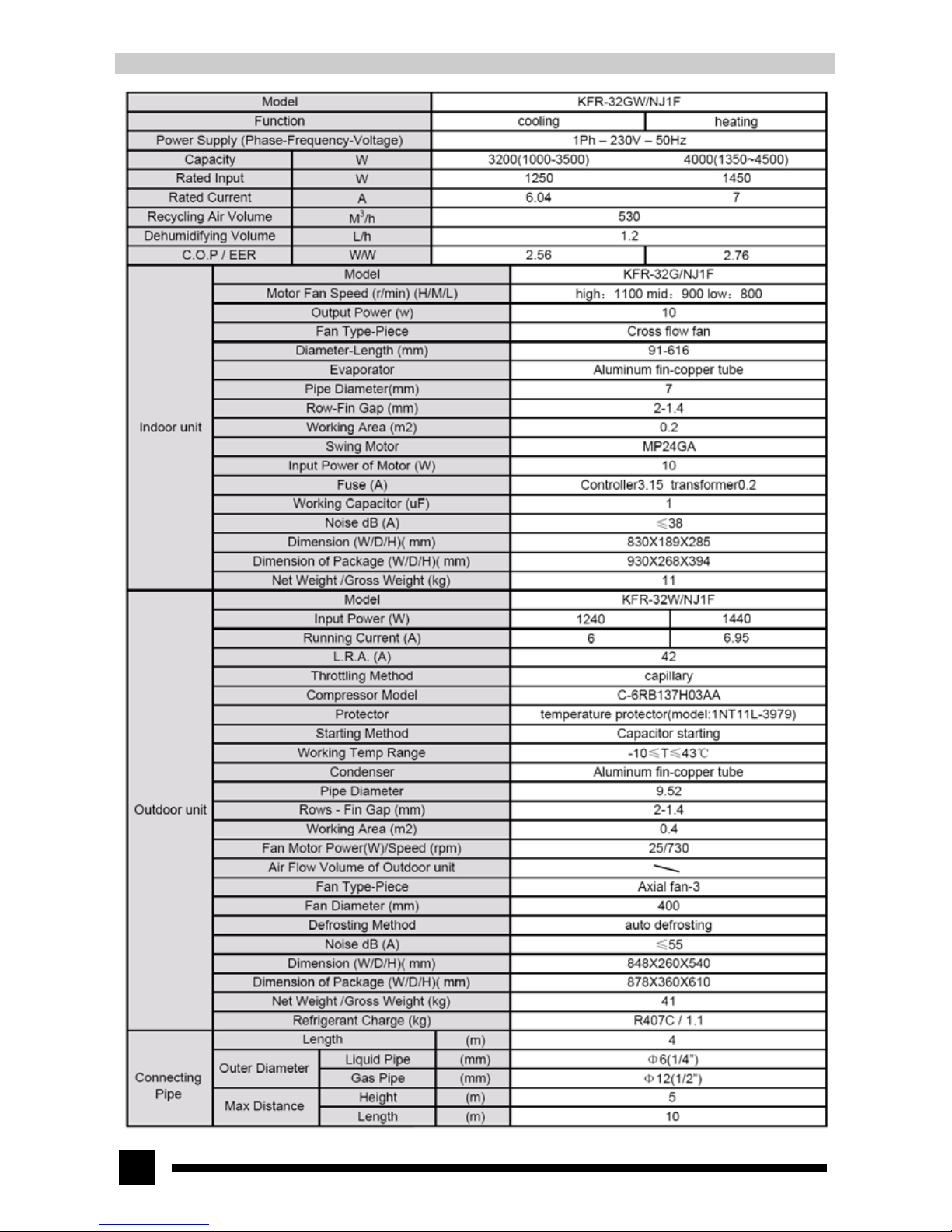
2. Specifications and technical parameters
Page 4
4
Page 5
5
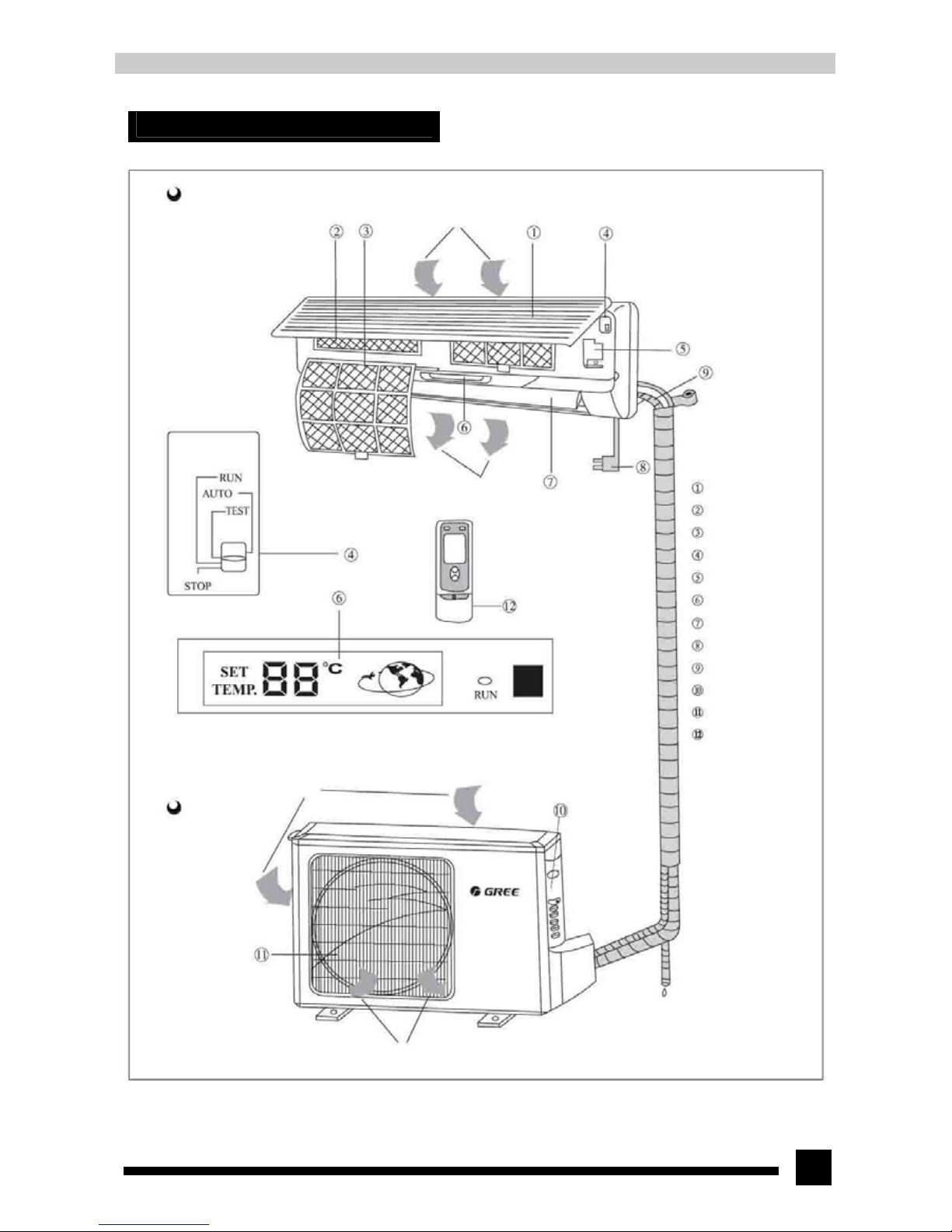
3. Part name
Indoor unit
Air in
Air out
Signal receiver
* When air conditioner is turned on by the wireless remote controller, the run indicator is on
(green). This light blinks while defrosting.
Air in
Outdoor unit
Air out
Front panel
Filter
Purifier filter
Operation switch
Electric box cover
LCD
Guide louver
Power plug
Drainage hose
Big handle
Air outlet vent grill
Wireless remote
controller
Page 6
6
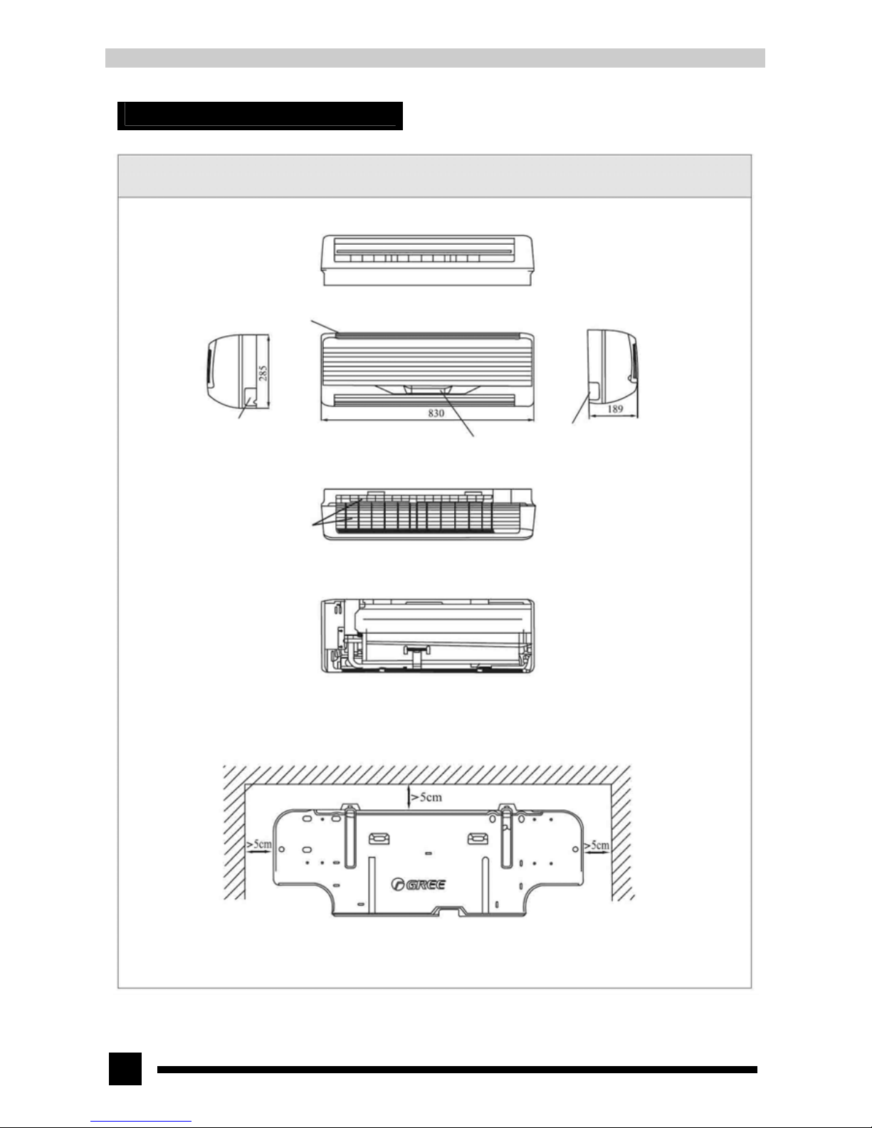
4. Outline and installation dimension
4.1. Outline and installation dimension of indoor unit
Air inlet hole
Right piping hole flag
Piping hole flag
Liquid crystal display and reception window
Air inlet hole
Rear view
Left
Ceiling
Right
Wall mounting plate
Page 7
7
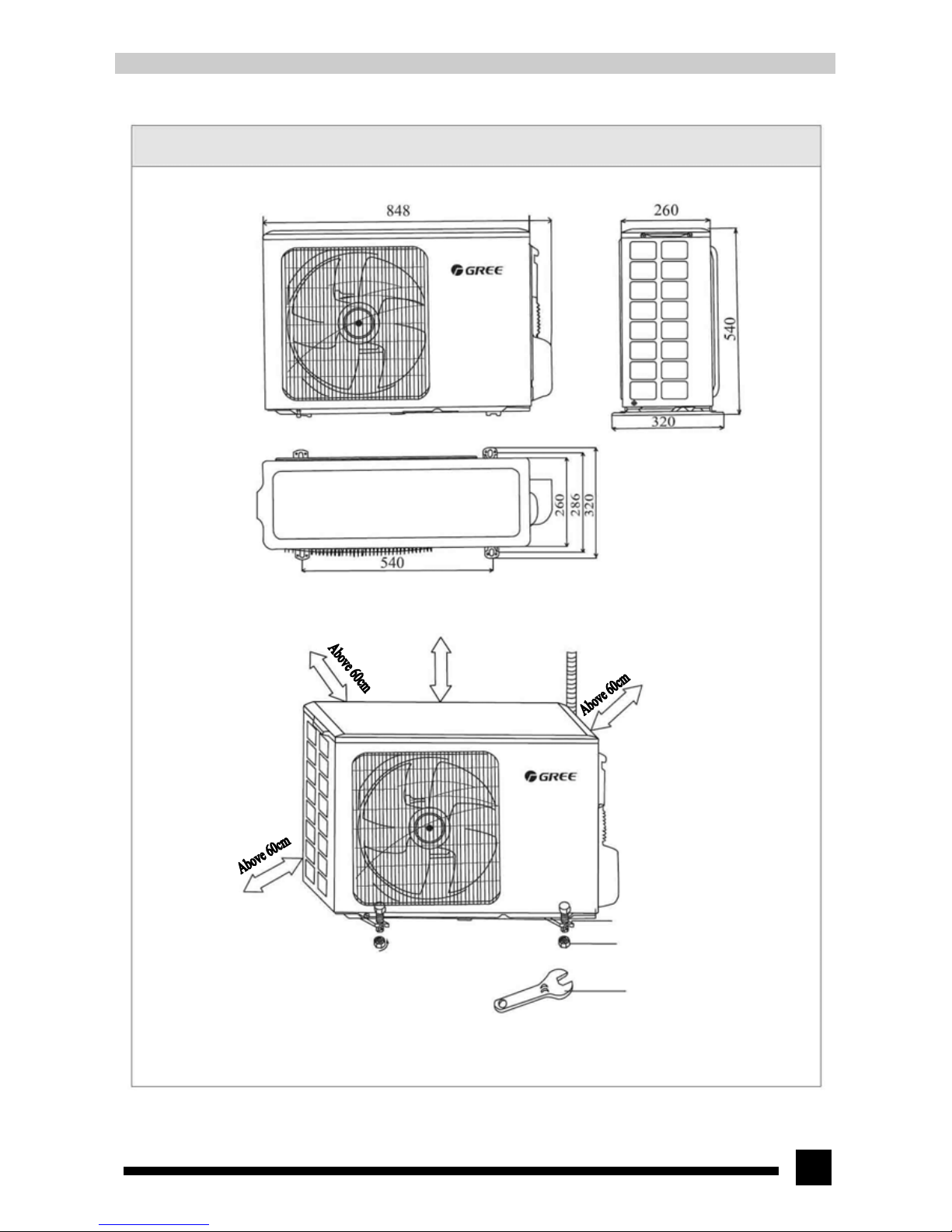
4.2. Outline and installation dimension of outdoor unit
Unit: mm
Above 60cm
Bolt
Nut
Spanner
Page 8
8
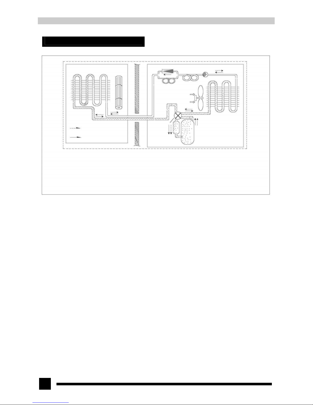
5. System schematic diagram
Evaporator Cross flow fan
Refrigerant flowing direction
when heating
Refrigerant flowing direction
when cooling
One-way valve Filter
Main capillary
Auxiliary capillary
Axial flow fan
Condenser
Electromagnetic
four-way valve
Gas liquid separator Compressor
When powered on, indoor and outdoor unit will start to run. When the system operates in cool mode, the compressor sucks low-temperature,
low-pressure refrigerant gas from indoor evaporator, compresses it into high-temperature, high-pressure refrigerant gas and discharges it into outdoor
heat exchanger. With the help of axial flow fan, the gas transfers its latent heat into outdoor air and becomes refrigerant liquid. The liquid is throttled
by throttling device and changes into low-temperature and low-pressure liquid and then flows into indoor heat exchanger. With the help of indoor unit
cross flow fan, the liquid becomes low-pressure refrigerant gas after it exchanges heat with indoor air. Such cycles are repeated continuously to
achieve cooling effect. When the system operates in heat mode, the four-way valve changes its way and the refrigerant flows into the reversed cycle
of the cool mode. The refrigerant discharges its latent heat indoor through the heat exchanger, and sucks heat from outdoor heat exchanger and forms
the heat pump cycle to achieve heating effect.
Page 9
9
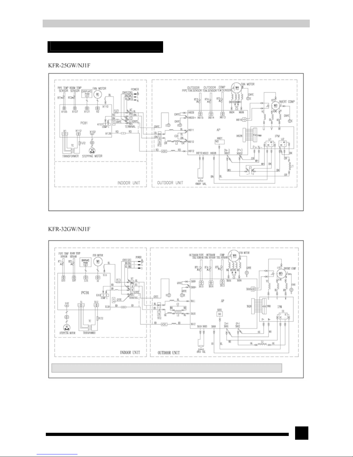
6. Electrical circuit diagram
These circuit diagrams are subject to change without notice. Please refer to the one supplied with the unit.
Page 10
10
7. Function manual and operation method of remote controller
7.1 Temperature parameters
◆ Room set temperature(T
set
)
◆ Room ambient temperature(T
amb
)
◆ Outdoor ambient temperature(T
oamb
)
◆ Evaporator temperature(T
eva
)
◆ Surface temperature of heat exchanger copper pipe of outdoor unit T
tub1
◆ Surface temperature of heat exchanger copper pipe of indoor unit T
tub2
7.2 Fundamental functions
7.2.1 Cool mode
1. The condition and process of cooling
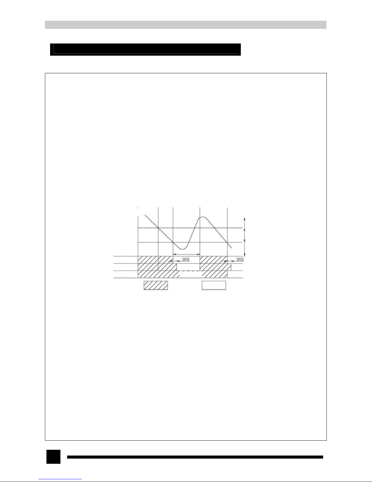
◆ If T
amb≥Tset
, COOL mode will act, the compressor, outdoor fan and indoor fan will run, and the indoor fan will run at the set
speed.
◆ If T
amb≤Tset
-2℃,the compressor will stop , the outdoor fan will delay 30sec to stop and the indoor fan will run at the set speed.
◆ If Tset-2℃<T
amb<Tset
, the unit will keep running in the previous mode.
Ambient temperature T
amb
Set temperature T
set
T
set
-2℃
3 min
Compressor
Outdoor fan
COOL mode will act
Keep running in original state
COOL mode will stop
Indoor fan Run at the set speed
Run Stop
◆ In this mode, the reversal valve will not be powered on and the temperature setting range is 16℃~30℃
2. Antifreezing protection
In COOL mode, when the antifreezing protection is detected, the compressor will stop and the outdoor fan will stop after 30sec. The
indoor fan and swing fan will keep running in the original mode. When antifreezing protection is eliminated, the unit will restart
automatically and enter into original running state.
7.2.2 DRY mode
1. The condition and process of dehumidifying:
◆ If T
amb>Tset
, DRY mode will act, the indoor fan, outdoor fan and compressor will run, and the indoor fan will run at low speed
◆ If T
set
-2℃≤T
amb≤Tset
, the unit will keep running in the original mode.
◆ If T
amb<Tset
-2℃,the compressor will stop, the outdoor fan will delay 30sec to stop and indoor fan will run at low speed.
Page 11
11
2 Antifreezing protection: the same with that in COOL mode.
7.2.3 FAN mode
The control condition of AUTO fan speed:
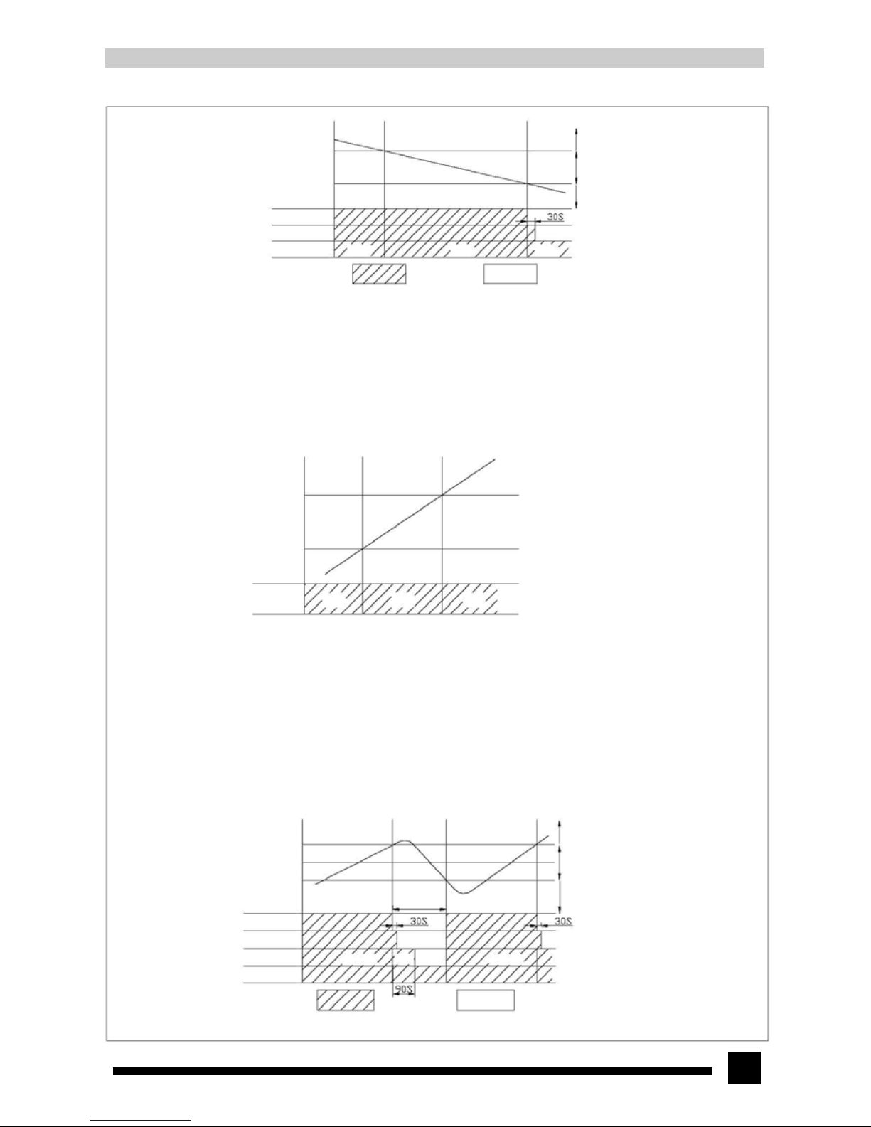
◆ If Tamb>Tset +4℃,set High speed automatically.
◆If Tset+2℃≤Tamb ≤Tset +4℃, set Med speed automatically.
◆ If Tamb<Tse t+2℃, set Low speed automatically
◆ In this mode, the indoor fan can select High, Med, Low and Auto mode and both the compressor and outdoor fan stop ruuning.
◆ In this mode, the temperature setting range is 16℃~30℃
7.2.4 HEAT mode
1. The condition and process of heating
◆ If Tamb≤Tset+2℃,HEAT mode will act,the compressor, outdoor fan and reversal valve will run at the same time, and the
indoor fan will run in anti-cold-wind mode.
◆ If Tset+2℃<Tam b<T set +5℃,the unit will keep running in the original mode.
◆ If Tamb≥Tse t +5 ℃,the compressor will stop, the outdoor fan will delay 30sec to stop and the indoor fan will blow at the low
speed for 90sec and then stop.
11
Ambient temperature Tamb
COOL mode will act
DRY mode will act
COOL mode will stop
Set temperature Tset
Tset -2℃
Low s
p
eed Low speed Low speed
Run Stop
Compressor
Outdoor fan
Indoor fan
Ambient temperature Tamb
Tset +4℃
Tset +2℃
Indoo
r
Low speed Med speed High speed
Ambient temperature Tamb
Set temperature Tset
HEAT mode will stop
Keep running in original state
HEAT mode will act
Tset +5℃
Tset +2℃
3 min
Anti-cold-wind mode
Low
speed
Anti-cold-wind mode
Run Stop
Compressor
Outdoor fan
Indoor fan
Reversal valve
Page 12
12
2. The condition and process of defrosting
When heating time runs more than 45min continuously, defrosting condition is satisfied and the unit will enter into defrosting state.
At this time the compressor stops, the indoor fan stops, the outdoor fan will delay 30sec to stop and the four-way valve will stop after
30sec; after another 60sec,the compressor will run. The indoor run indicator light will blink while defrosting. When the compressor
has run for 6min or Ttub≥10℃, the compressor will stop, the four-way valve will open after 30sec and the run indicator will stop
blinking. After another 90sec, the compressor and outdoor fan will resume running and the indoor fan will run in anti-cold-wind
mode.
3. The condition of anti-cold-wind mode:
After the compressor has run for 3min, the indoor fan will run at the set speed.
7.3 AUTO mode
1. The condition and process of AUTO mode
◆Cooling Tset=25℃,Heating Tset=20℃.
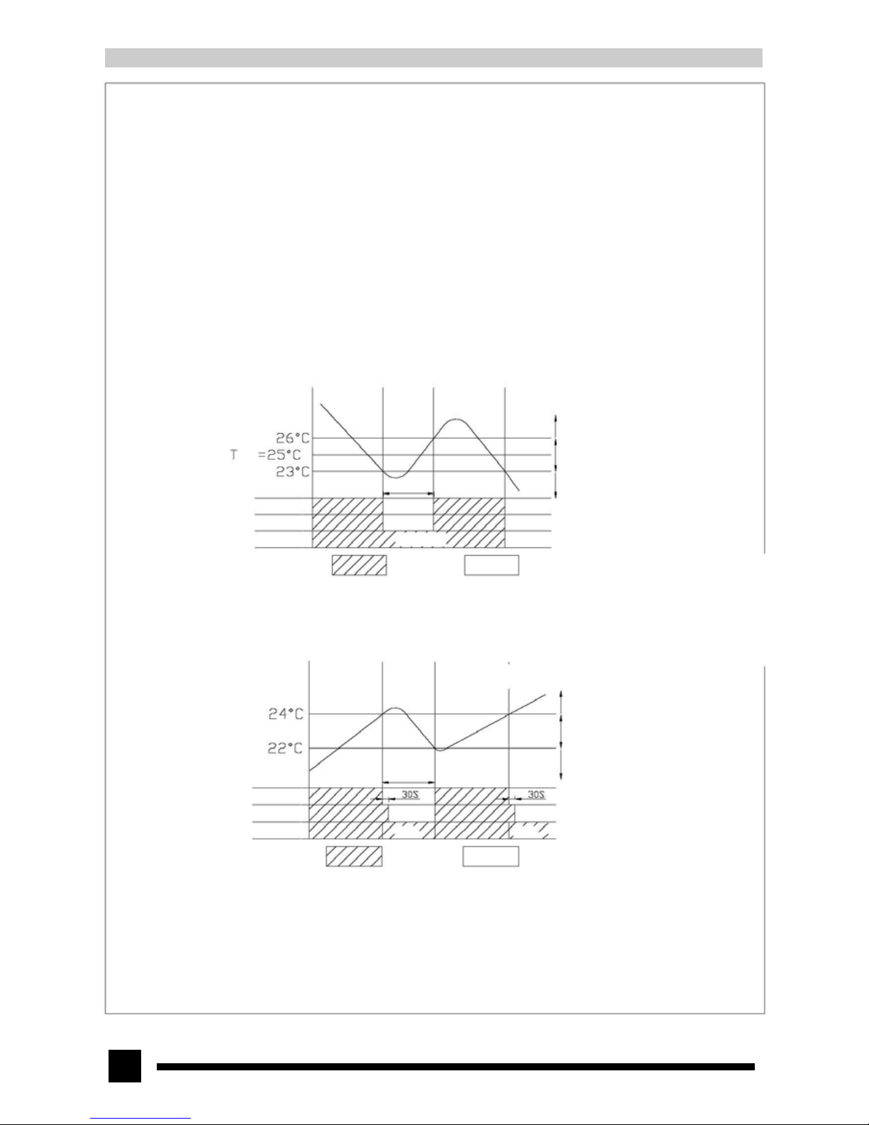
◆ If T amb>Tset +1℃, COOL mode will act. At this time the hidden set temperature is 25℃. If T amb≤Tset - 2℃, the compressor
and outdoor fan will stop, the indoor fan will run at the set speed; if Tset-2℃<Tamb≤Tset+1℃, the unit will keep running in
the original mode.
◆If Tamb≤Tset+2℃, HEAT mode will act. At this time the hidden set temperature is 20℃. If Tamb≥Tset+4℃, the compressor
will stop, the outdoor fan will delay 30sec to stop and the indoor fan will run at low speed; if Tset+2℃<Tamb<Tset+4℃, the unit
will keep running in the original mode.
◆ If 22℃<Tamb<26℃, FAN mode will act. The displayed temperature is 23℃.
2. Protection function:
◆
In COOL mode, protection function is the same with that in COOL mode.
◆ In HEAT mode, heating, protection function is the same with that in HEAT mode.
◆ When ambient temperature changes, mode switch is in priority. There is no 6-minute delay after the compressor starts to run.
Ambient temperature Tamb
COOL mode will act
Keep running in the original state
COOL mode will stop
3min
Run
Sto
p
Compressor
Outdoor fan
Indoor fan
Run at the set s
p
eed
Ambient temperature Tamb
HEAT mode will stop
Keep running in original state
HEAT mode will act
3min
Run
Sto
p
Compressor
Outdoor fan
Indoor fan
Low speed
Low speed
Page 13
13
7.4 Common protection function and malfunction display of COOL, HEAT, DRY and AUTO mode
1. Overload protection:
T
tub
: Measure the temperature of outdoor heat exchanger when cooling and measure the temperature of indoor heat exchanger when
heating
◆ When tube temperature exceeds a certain specified value, the indoor fan will run at the set speed and the compressor will stop
running.
◆ When tube temperature is back to normal, the unit will resume running in the original state.
2. Compressor delay protection:
The compressor will delay 3min to start again after stopping.
3. Compressor discharge temperature (Tdis) protection
If the discharge temperature exceeds a certain specified value, the compressor will stop; when the discharge temperature is
detected normal after 3min, the compressor will start to run.
7.5 Other control
1. Emergency control
Auto button:
If the wireless remote control is lost, use this button. Place the switch at this position to set the unit running in AUTO mode. The
indoor fan runs in auto speed and the guide louver runs in SWING mode. The backlight is on in AUTO mode. If this is remote signal,
the unit will run according to remote signal.
Test button:
Place the switch at this position to set the unit running in COOL mode. The indoor fan runs at high speed and the guide louver runs in
SWING mode. The backlight is turned on. If this is remote signal, the unit will run according to remote signal. When the wireless
remote controller is used to select COOL mode, the unit will be turned on in SAVE mode and it will run in COOL mode according to
nominal cooling capacity. The indoor fan runs at high speed and the swing fan runs; when the wireless remote controller is used to
select HEAT mode, the unit will be turned on in SAVE mode and it will run in HEAT mode according to nominal heating capacity.
The indoor fan runs at high speed and the swing fan runs.
Run button:
Place the switch at this position and the unit will run according to the received remote signal.
Stop button:
Place the switch at this position and the whole unit will stop running.
2. Sleep control
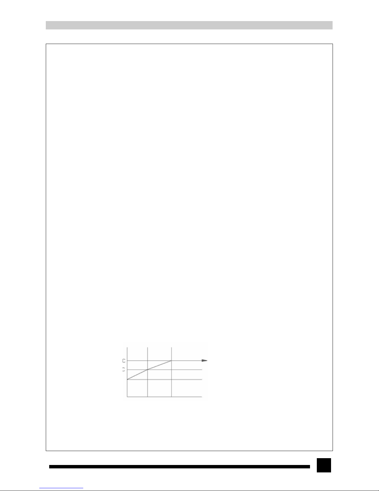
◆ When the air conditioner is in COOL or DRY mode, after Sleep mode has been set properly, the preset T
set
will be increased
by 1℃ after the sleep program has run for 1 hour, and T
set
will be increased by another 1℃ after 2 hours. T
set
has been
increased by 2℃ totally in two hours. Then the unit will run at this set temperature.
Set temperature Tset
1h 2h
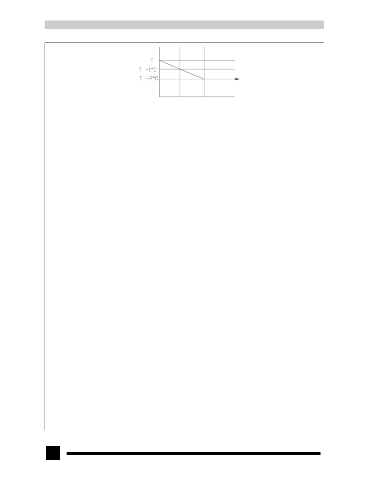
◆ When the air conditioner is in HEAT mode, after Sleep mode has been set properly, the preset T
set
will be decreased by 1℃
after the sleep program has run for 1 hour, and T
set
will be decreased by another 1℃ after 2 hours. T
set
has been increased by 2
℃ totally in two hours. Then the unit will run at this set temperature.
Page 14
14
1h 2h
◆ In FAN and AUTO mode, the set temperature is fixed.
3. Indoor fan control
Indoor fan can be set in HIGH, MED and LOW mode with button. At this time, the fan will run at high, medium and low speed
respectively. It can also be set in AUTO mode and at this time the fan speed will be selected according to the compressor’s running
frequency. The indoor fan run at low speed in FAN mode.
4. Swing option
Press the SWING button to control its ON and OFF. Swing can only be activated when indoor fan is running.
5. Buzzer
When the air conditioner is powered on or receives valid signal or button input from the wireless remote control, the buzzer will send
out a sound.
6. Auto fan control
The indoor fan has High, Med and Low three levels of fan speed according to different frequencies. In FAN mode, the fan will run at
low speed in Auto mode.
Page 15
15
7.6 Names and functions of each button of wireless remote controller
NOTE:
Make sure that there are no obstructions between the receiver and wireless remote control.
The wireless remote control signal can be received at the distance of up to about 10m.
Do not drop or throw the wireless remote control.
Do not let any liquid flow into the wireless remote control or put it directly under the sunlight or any extremely hot places.
When the system stops and restarts, it can resume its original running mode and the outdoor unit will run after a while.
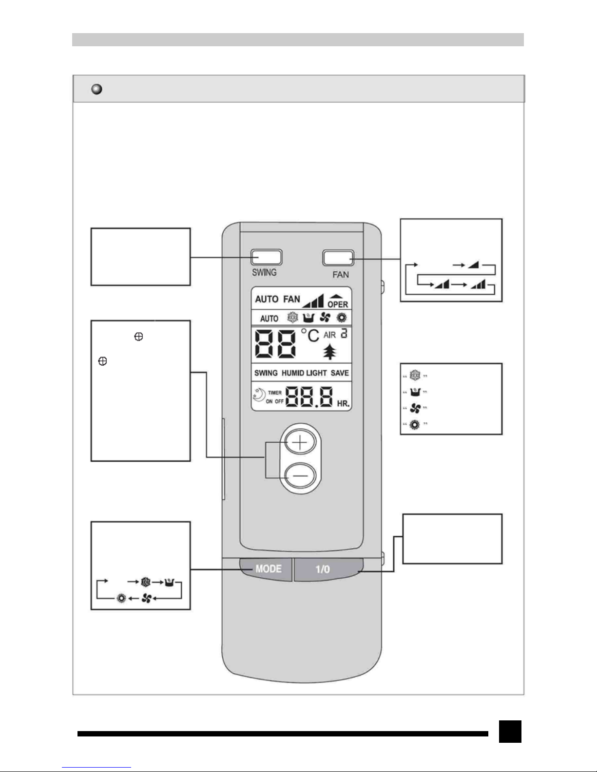
SWING button
When it is pressed, the
guide louver starts to swing
at the stated angle and stops
when it is pressed again.
FAN button
Each time this button is
pressed, fan speed will change
in the following order:
AUTO FAN
TEMP. button
Each time “ ” is pressed,
the set temperature will be
increased by 1℃ and each time
“ ” is pressed, the temperature
will be decreased by 1℃.
In Cool mode, room temperature
setting range is 16℃-30℃.
In DRY mode, room temperature
setting range is 16℃-30℃.
In HEAT mode, room temperature
setting range is 16℃-30℃.
In AUTO mode, temperature cannot
be adjusted.
indicates COOL mode.
indicates DRY mode.
indicates FAN mode.
indicates HEAT mode.
MODE button
Press this button
successively to change
running mode in the
following order.
AUTO
On/Off button
Press the button to turn on
the unit. Press the button
once again to turn off the
unit.
Page 16
16
7.7 Names and functions of each button of wireless remote control (Cover op ened)
NOTE: ● This wireless remote control is a type of general-purpose controller, which may be applied to multiple types (functions)
of air conditioners. Some buttons of this controller that are not applicable to this air conditioner will not be described
below. We are sorry for the inconvenience.
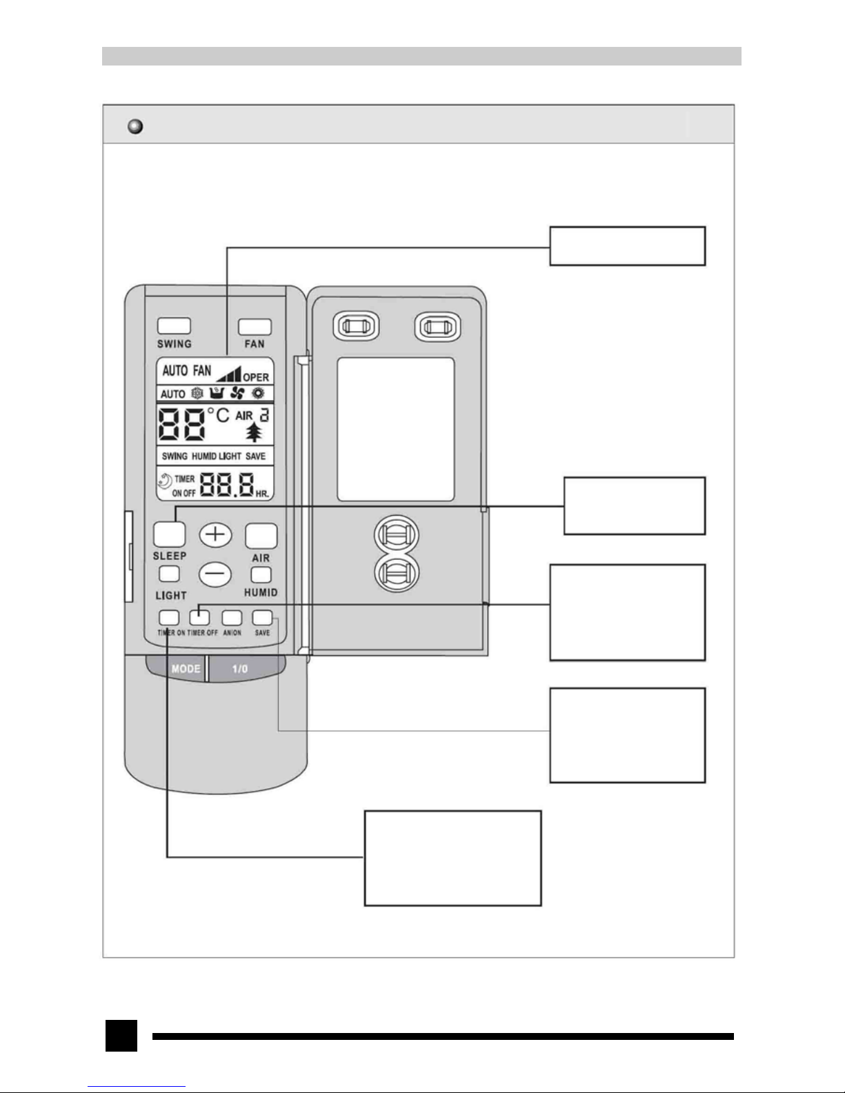
LCD
It shows all selected contents.
SLEEP button
Press this button once to set
SLEEP operation and press it once
again to exit SLEEP operation.
TIMER OFF button
Under running state, press the
TIMER OFF button to set
timed turn-off in range of
0-24h.
Place the manual switch to
TEST and press the SAVE
button to set the air conditioner
running in nominal cooling and
heating capacity.
TIMER ON button
Under turn-off state, press the
TIMER ON to set timed
turn-on in range of 0-24h.
Page 17
17
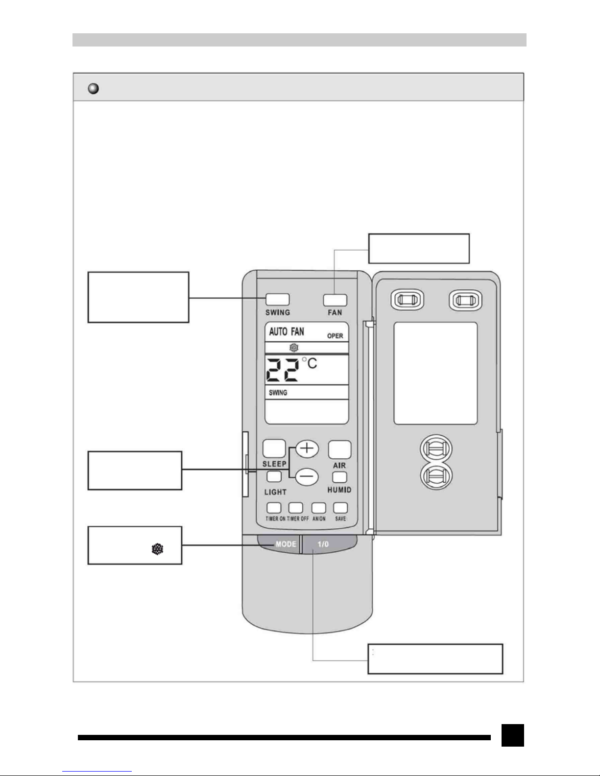
7.8 COOL mode operation
● According to room temperature, set temperature and the change rate of room temperature, microcomputer of the remote
controller will be able to control the output cooling capacity of the outdoor compressor.
● If room temperature is equal to or slightly higher than the set temperature, the compressor will run. If room temperature is 2.5
℃ higher than the set temperature, the compressor will run at its max. capacity. If the difference between room temperature
and set temperature is between 1℃ and 2.5℃, the compressor will stop, the outdoor fan will stop after 30sec and the indoor
fan will run at low speed.
● If the fan is set at AUTO mode, microcomputer of the remote controller can control the speed of indoor fan via the output
power of outdoor compressor.
● In this mode, the temperature setting range is 16℃~30℃.
● At this time, the LCD appears green.
4. Press the FAN button to
set fan speed.
3. Press the SWING button
and the guide louver starts
to swing automatically and
stops when it is pressed
again.
5. Press the TEMP
button to set the desired
temperature.
2. Press the MODE
button to select “ ”
mode.
1. After power-on, press the “1/0”
button to set the air conditioner
running.
Page 18
18
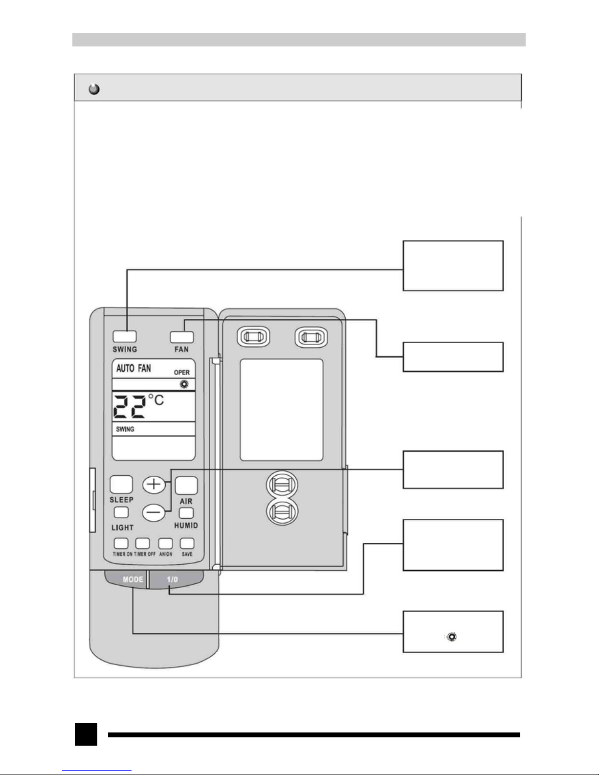
7.9 HEAT mode operation
● According to room temperature, set temperature and the change rate of room temperature, microcomputer of the remote
controller will be able to control the output heating capacity of the outdoor compressor.
● If room temperature is equal to or slightly lower than the set temperature, the compressor will run. If set temperature is 2.5℃
higher than the room temperature, the compressor will run at its max. capacity. If the difference between room temperature and
set temperature is between 1℃ and 2.5℃, the compressor will stop, the outdoor fan will stop after 30sec and the indoor fan will
run at low speed.
● If the fan is set at AUTO mode, microcomputer of the remote controller can control the speed of indoor fan via the output power
of outdoor compressor.
● In this mode, the temperature setting range is 16℃~30℃.
● At this time, the LCD appears green.
3. Press the SWING button
and the guide louver starts
to swing automatically and
stops when it is pressed
again.
4. Press the FAN button to
set fan speed.
5. Press the TEMP button
to set the desired
temperature.
1. After power-on, press
the “1/0” button to set the
air conditioner running.
2. Press the MODE button
to select “ ” mode.
Page 19
19
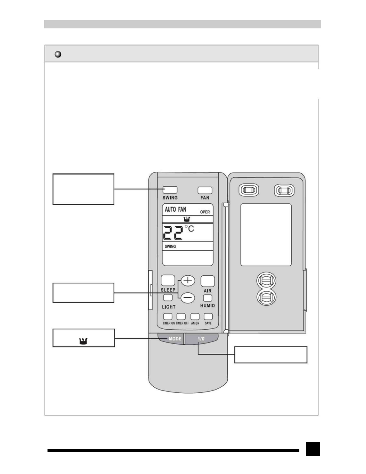
7.10 DRY mode operation
● If room temperature is higher than the set temperature, the compressor will run at the fixed frequency and the indoor fan
will run at low speed. If room temperature is 2℃ lower than the set temperature, the compressor will stop, the outdoor fan
will stop after 30sec and the indoor fan will stop immediately and start running at low speed after 5min.
● In this mode, the temperature setting range is 16℃~30℃.
● At this time, the LCD appears green.
3. Press the SWING button
and the guide louver starts to
swing automatically and stops
when it is pressed again.
4. Press the TEMP button to
set the desired temperature.
2. Press the MODE button
to select “ ” mode.
1. After power-on, press the “1/0” button to
set the air conditioner running.
Page 20
20
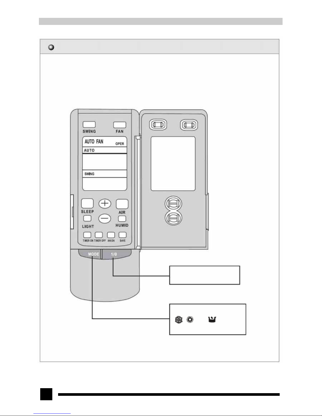
7.11 AUTO mode operation
● In AUTO mode, the standard temperature setting of COOL mode is 25℃ and the standard temperature setting of HEAT mode
is 20℃.
1. After power-on, press the “1/0” button to
set the air conditioner running.
2. Press the MODE button to select AUTO
mode and the microcomputer will select
“ ”, “ ” and “ ” running mode
automatically according to room
temperature to achieve the most
comfortable effect.
Page 21
21
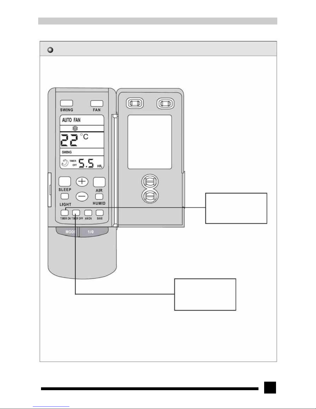
7.12 TIMER operation mode
Under turn-off state, press the
TIMER ON button to set the
timed turn-on in range of 0 to
24 hours.
Under turn-on state, press the
TIMER OFF button to set the
timed turn-off in range of 0 to
24 hours.
Page 22
22
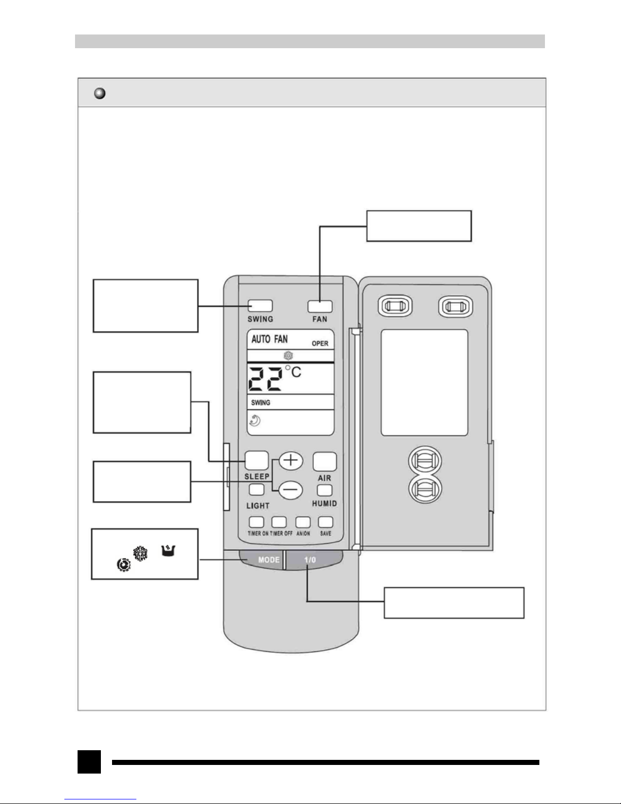
7.13 SLEEP mode operation
In COOL and DRY mode, after the SLEEP program has run for 1 hour, the set temperature will be increased by 1℃ in the
first hour, and increased by 2℃ in the second hour. Then the unit will run at this set temperature.
In HEAT mode, after the SLEEP program has run for 1 hour, the set temperature will be decreased by 1℃ in the first hour,
and decreased by 2℃ in the second hour. Then the unit will run at this set temperature.
4. Press the FAN button to
set fan speed.
3. Press the SWING button
and the guide louver starts
to swing automatically
6. Press the SLEEP button
to select SLEEP mode and
press it once again to exit
SLEEP mode.
5. Press the TEMP button
to set the desired
temperature.
2. Press the MODE button
to select “ ”, “ ”
and “ ” mode.
1. After power-on, press the “1/0”
button to set the air conditioner running.
Page 23
23
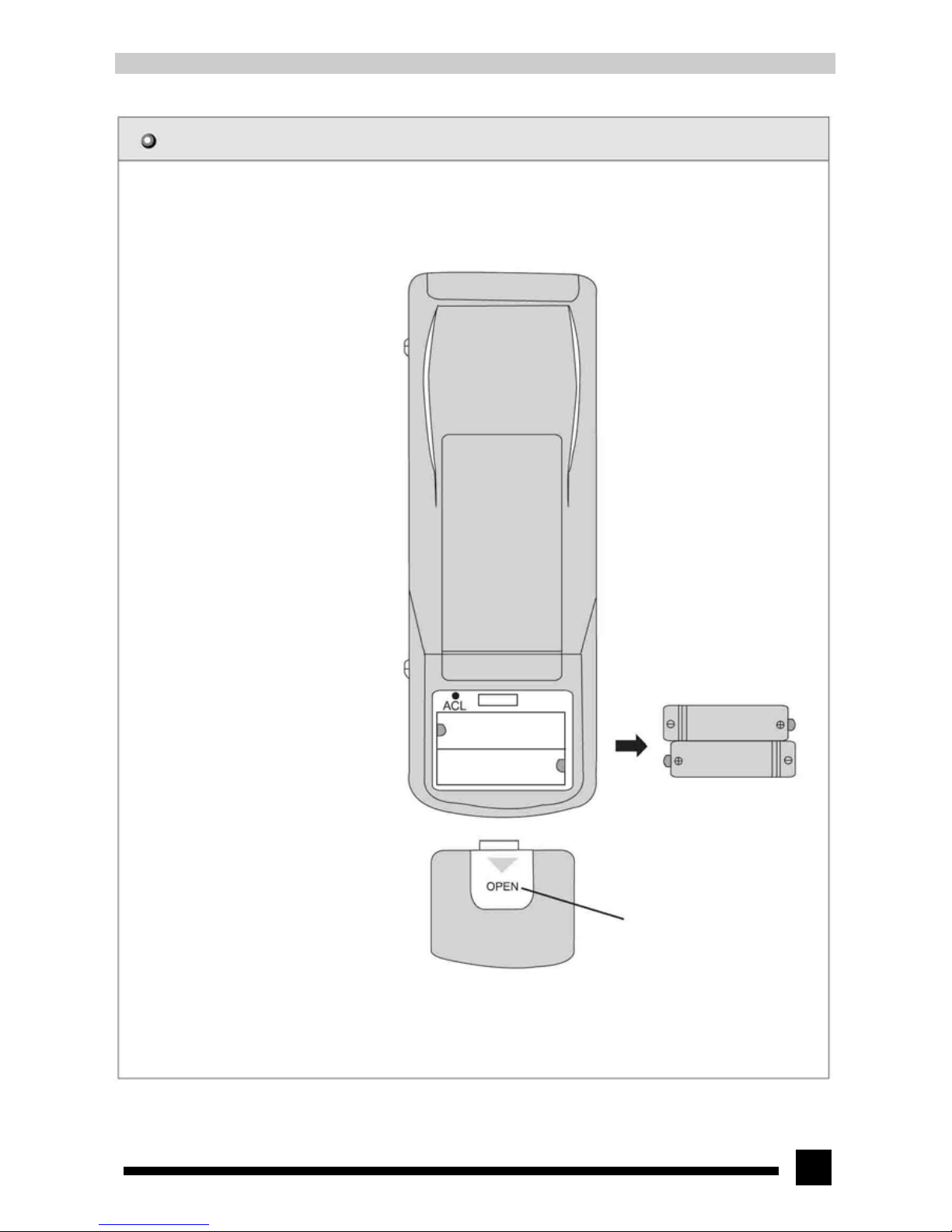
7.14 How to replace batteries
1. Slide down the battery cover of the remote
controller and remove the old batteries.
2. Replace with two new ones (be careful
about correctness of the polarities)
3. Re-attach the cover.
NOTE:
● Do not mix new and used or different types
of batteries for use.
● Take out the batteries if the wireless remote
controller will not be in use for a long time.
● The operation of the remote controller must
be within 10 meters for reception.
● Battery life is about one year.
● Remote controller should be more than one
meter's distance to TV or Hi-Fi
equipments.
2. Insert 2 AAA batteries
1. Remove the cover
3. Re-attach the cover
Page 24
24
8. Disassembly procedures
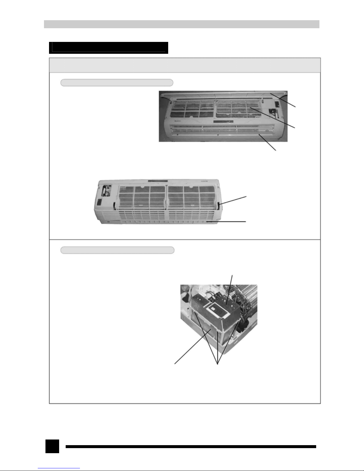
8.1 Operation procedures/pictures (Disassembly procedures for indoor unit)
8.1.1 Disassembling the front panel assy
Lift the front panel upward. Pull the panel
outward with strength along the grooves
that fix the front panel and take it out. (As
shown in Fig.8-1)
Take out the three screw covers and screw
off the three pieces of tapping screws.
Then use screwdriver to push up the clasp
that is fixed into the panel body at its back
inward and take off the front panel
assy.(As shown in Fig.8-2)
Front panel
Filter
Fig. 8-1
Screw cover (3)
Tapping screws (3)
Groove
Clasp
Fig.8-2
8.1.2 Disassembling the electric box
Take out the electric box cover with a bit strength, or
push up the clasps (3) that are fixed into the electric
box inward to take out the electric box cover.(As
shown in Fig.8-3)
Electric box
Electric box cover
Clasps
Fig.8-3
Page 25
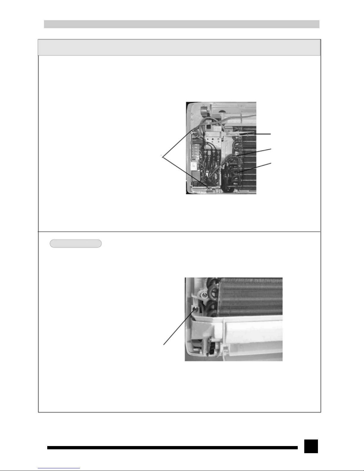
25
Operation procedures/picture
● Screw off the two pieces of screws that fix the
electric box with screwdriver and take out the
water-retaining rubber piece on the evaporator.
Remove the grounding wire on the evaporator and
pull out the tube sensor. Cut off the wire clip with
scissor and unplug the connector terminal of indoor
motor and stepping motor etc. Then unclench the
clasp that fixes the electric box on the rear case to
take out the electric box. (As shown in Fig.8-4)
Fig.8-4
8.1.3 Disassembling the water tray assy
● Screw off the tapping screws that fix the water tray
assy on the left. Push out the clasp in the middle of
the water tray from the rear case and pull out the
water tray assy with strength. Be careful because the
drainage pipe is placed here. (As shown in Fig.8-5)
Tapping screws
Fig.8-5
Screws
Room sensor
Groundin
g
wire
Tube sensor
Page 26
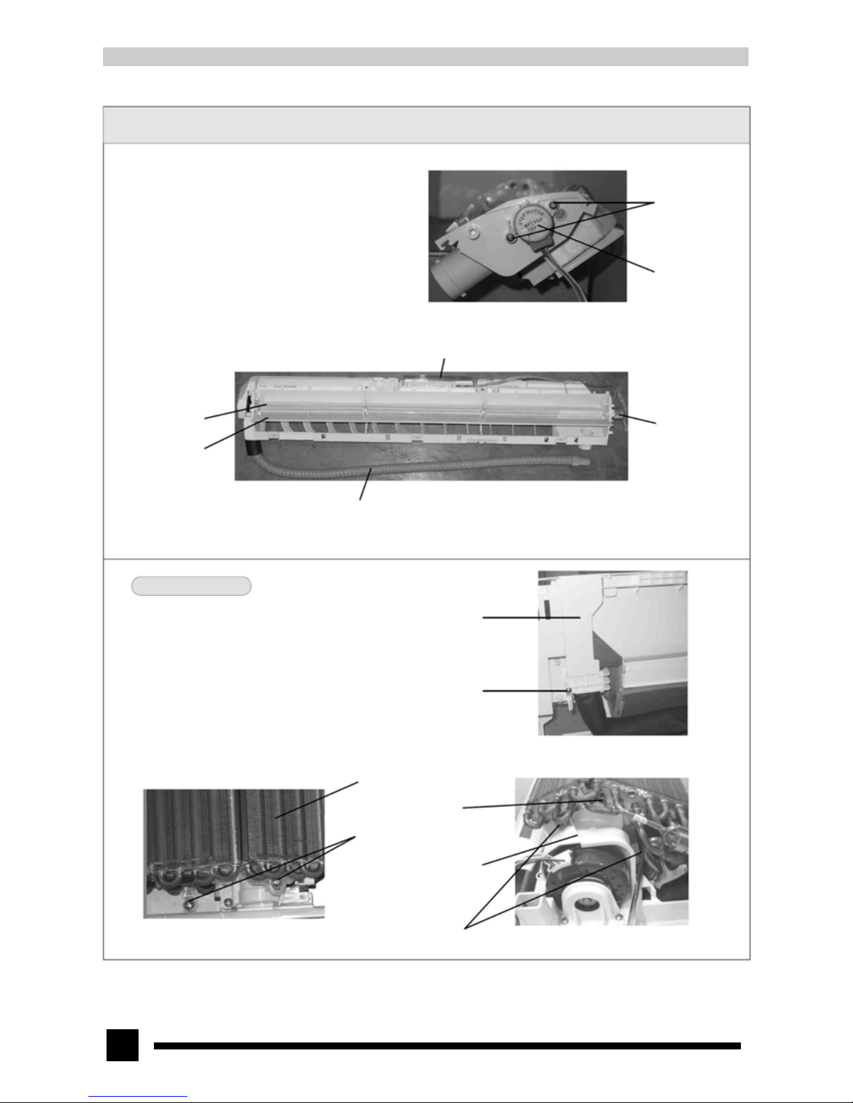
26
Operation procedures/pictures
● Press the connector of the drainage hose with
strength and turn the drainage hose
counterclockwise to take it off.
● Remove the big and small guide louver. Use your
fingers to bend them in the arrow direction with
strength to take off the guide louver. (As shown in
Fig.8-7)
● Screw out the screws that fix the guide motor to take
it off. (As shown in Fig.8-6)
● Unclench the clasp in the middle of the water tray
that fix the liquid crystal box to take out the liquid
crystal box.
8.1.4 Disassembling the evaporator assy
● At the back of the rear case, screw off the tapping
screws that fix the rear clamp and unclench the
clasp that fixes it into the rear case to take off the
rear clamp.(As shown in Fig.8-8)
● Screw off the tapping screws that fix the evaporator
on the rear case and the motor clamp. Unclench the
clasps and pull the liquid inlet pipe of the gas
collector on the back groove of the rear case slightly
outward. Pull out the left side of the evaporator and
pull the right side of the evaporator at the same time
to take it out along the grooves. Pay attention to
protecting the connecting pipe.(As shown in Fig.8-9
and 8-10)
Screws (2 pieces)
Guide motor
Fig.8-6
Liquid crystal box
Small guide louver
Guide motor
Big guide louver
Drainage hose
Fig.8-7
Rear clamp
Screws
Fig.8-8
Evaporato
r
Screws
Fig.8-9
Clasps
Right motor clamp
Screws
Fi
g
.8-10
Page 27
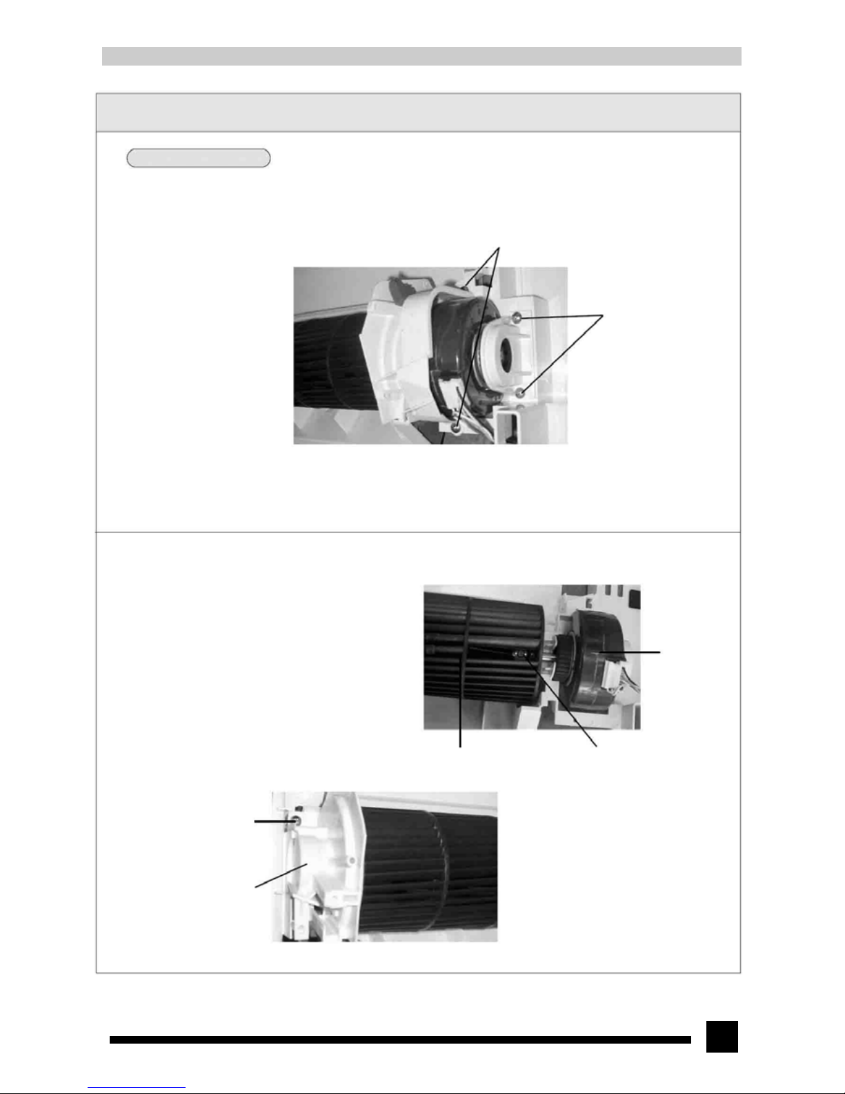
27
Operation procedures/pictures
8.1.5 Disassembling the cross flow fan and motor
● Screw out the two pieces of tapping screws on the
right side of the rear case that fix the right motor
clamp and the bearing support to take out the right
motor clamp and bearing support.(As shown in
Fig.8-11)
Fig.8-11
● Screw off the fixing screws on the right inside the
cross flow fan with screwdriver to take out the
motor enclosed by plastic. Pay attention to the angle
when the motor is installed.(As shown in Fig.8-12)
● Screw out the tapping screws on the left side of the
rear case that fix the left motor clamp to take off the
left motor clamp and then take out the cross flow
fan.(As shown in Fig.8-13)
Tapping screws
Left motor clamp
Fig.8-13
Screws
Screws
Bearing support
Right motor clamp
Motor
Cross flow fan Fixing screws
Fig.8-12
Page 28
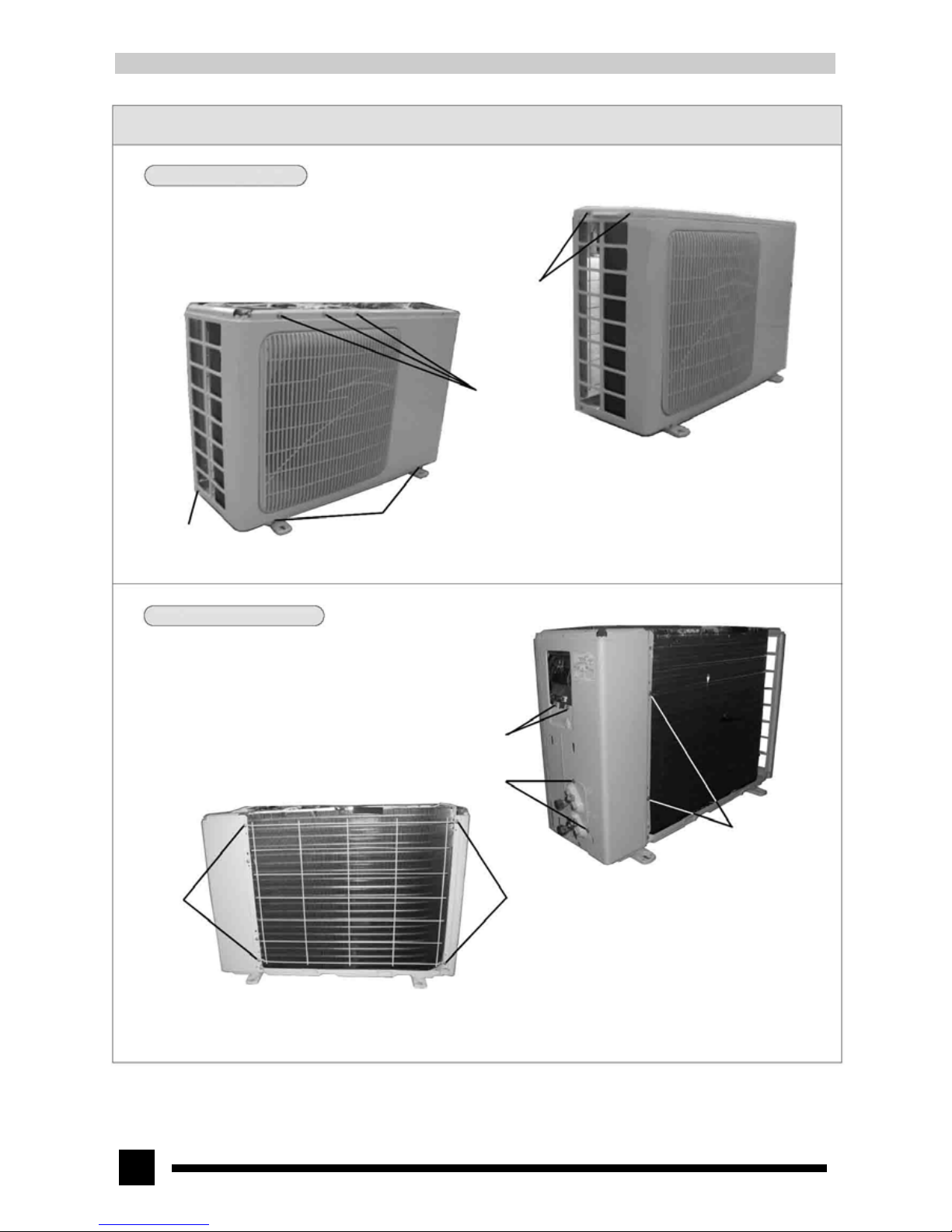
28
9.2.Operation procedures/pictures (Disassembly procedures for outdoor unit)
8.2.1 Disassembling the top cover and front panel
● Screw off the 2 pieces of screws on the left side and
1 on the right side and lift it upward to take off the
top cover. (As shown in Fig.8-14)
● Screw off the 5 pieces of screws on the front side
and 1 on the left side and take off the front panel
with strength. (As shown in Fig.8-15)
Fig.8-15
8.2.2 Disassembling the rear grill and right side plate
● Screw off the 4 pieces of screws on the rear grill to
take it off. (As shown in Fig.8-16)
● Screw off the 7 pieces of screws on the right side
plate to take it off. (As shown in Fig.8-17)
Screws
Screws
Fig.8-14
Screws
Screws
Screws
Screws
Screws
Screws Screws
Fig.8-16
Fig.8-17
Page 29
29
Operation procedures/pictures
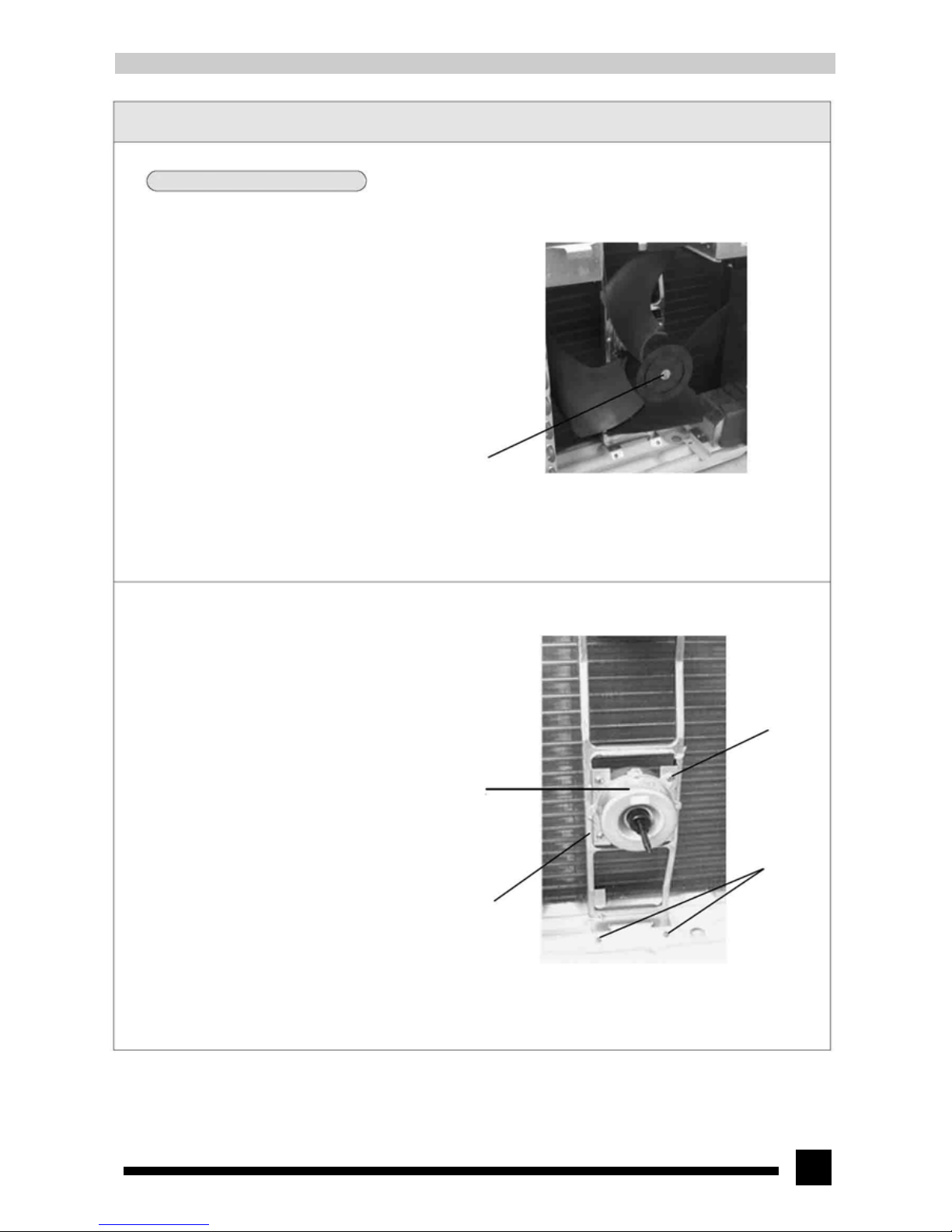
8.2.3 Disassembling the fan blade, motor and motor support
● Screw off the fixing nut, flap gasket and spring
gasket of the axial cross fan take out the axial flow
fan with strength.(As shown in Fig.8-18)
Fixing nut
Fig.8-18
● Screw off the 4 pieces of tapping screws that fix the
motor and unplug the lead wire insert of the motor
to take it off.(As shown in Fig.8-19)
● Screw off the 2 pieces of tapping screws that fix the
motor support and lift it upward to take off the
motor support.(As shown in Fig.8-19)
Fig.8-19
Motor
Motor support
Tapping screws
(4 pieces)
Tapping screws
Page 30
30
Operation procedures/pictures
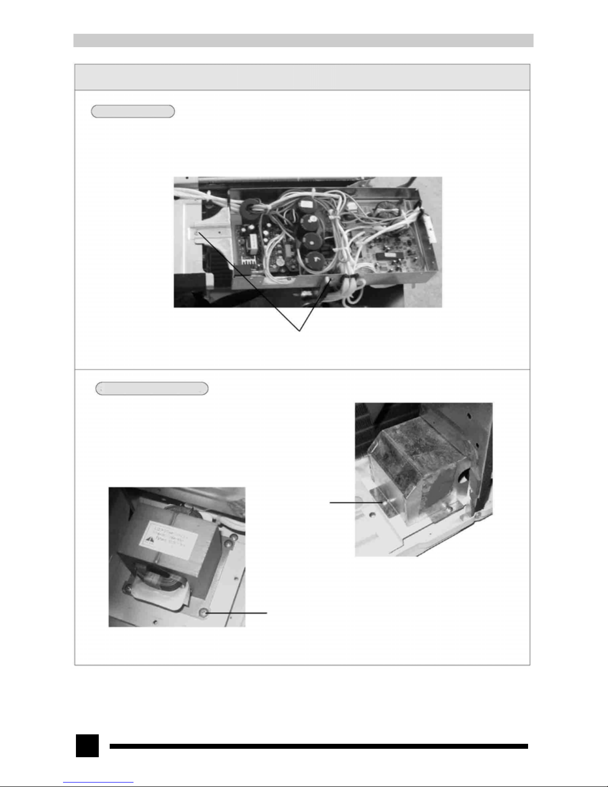
8.2.4 Disassembling the electric box
● Screw off the 2 pieces of screws that fix the electric
box and unplug the lead wire insert of the
compressor, reactor, four-way valve and fan motor
to take out the electric box (As shown in Fig.8-20)
Screws
Fig.8-20
8.2.5 Disassembling the reactor box and reactor
● Screw off the 3 pieces of screws between the reactor
box and the base plate to take out the reactor
box.(As shown in Fig.8-21)
● Screw off the 4 pieces of screws between the reactor
and the base plate to take out the reactor.(As shown
in Fig.8-22)
Screws (3 pieces)
Screws (4 pieces)
Fig.8-21
Fig.8-22
Page 31
31
Operation procedures/pictures
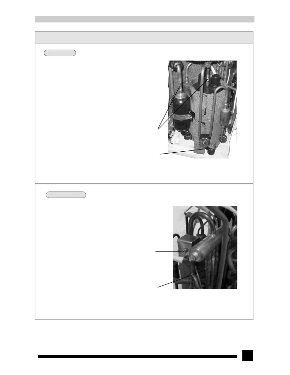
8.2.6 Disassembling the compressor
● Unloose the 3 pieces of nuts with gaskets; unsolder
the solder joints of the compressor's suction and
discharge pipe (As shown in Fig.8-23). Remove the
pipeline carefully and take out the compressor.
Solder joints
Nut with gasket (3 pieces)
Fig.8-23
8.2.7 Disassembling the electromagnetic four-way valve
● Screw off the fixing nut of the four-way valve coil
and remove the coil. Wrap the four-way valve with
wet sponge and unsolder the 4 solder joints on the
four-way valve to take off the four-way valve. (As
shown in Fig.8-24)
● Welding process should be as quick as possible and
the wetness of the wrapping sponge should be
maintained all the time. Be sure not to burn out the
lead wire of the compressor.
Fig.8-24
Fixing nut
Solder joint (4)
Page 32
32
Operation procedures/pictures
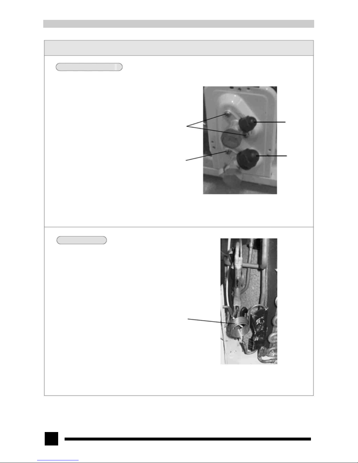
8.2.8 Disassembling the big valve and small valve
● Screw off the 2 pieces of bolts that fix the big valve
and unsolder the solder joint between the big valve
and air return pipe to take off the big valve.(As
shown in Fig.8-25)
(Note: When unsoldering solder joint, wrap the big valve
completely with wet cloth to avoid high-temperature damage
to the valve body.)
● Screw off the 2 pieces of bolts that fix the small
valve and unsolder the solder joint between the
capillary assy and the small valve to take off the
small valve.(As shown in Fig.8-25)
Fig.8-25
8.2.9 Disassembling the capillary assy
● Unsolder the 2 solder joints between the capillary
assy and the small valve and between the capillary
and the condenser to take off the capillary assy.(As
shown in Fig.8-26)
Capillary assy
Fig.8-26
Bolts
Small valve
Bolt (2 pieces)
Big valve
Page 33
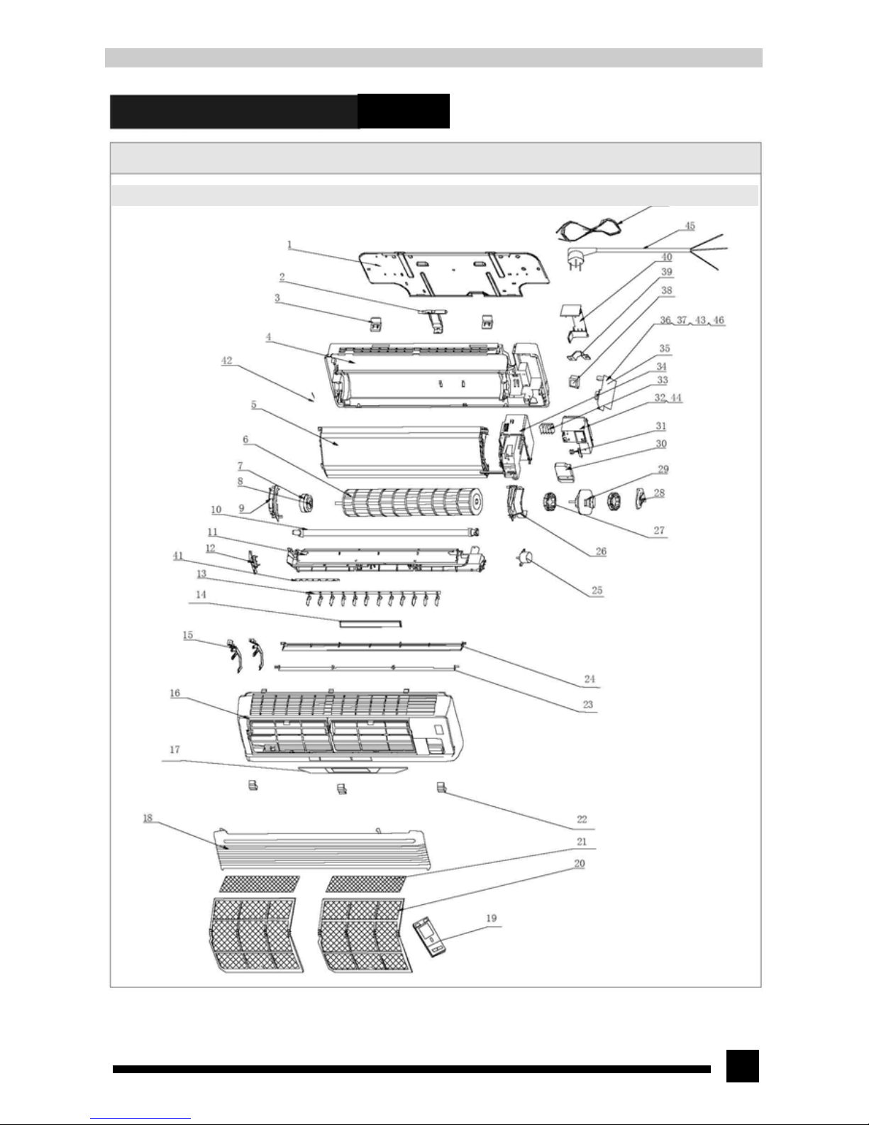
33
9.Explosive view and parts and components list
9.Explosive view of indoor unit
Page 34
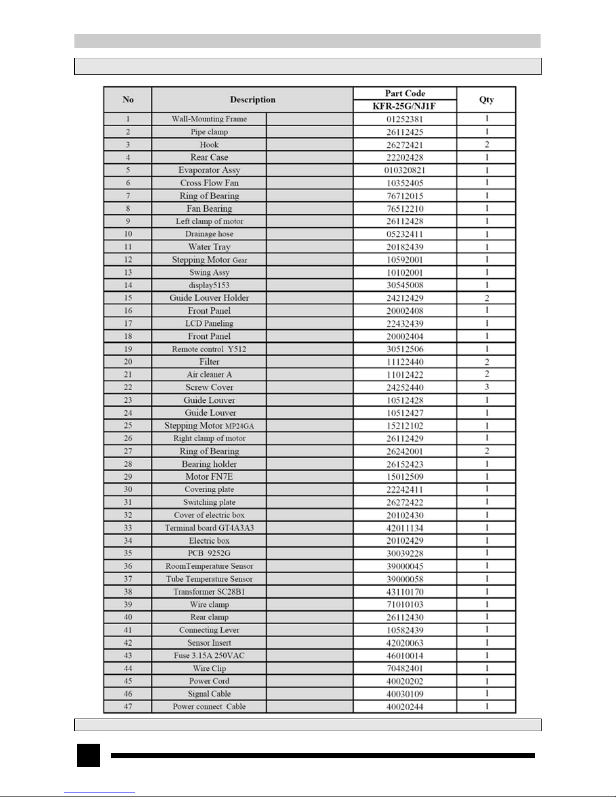
34
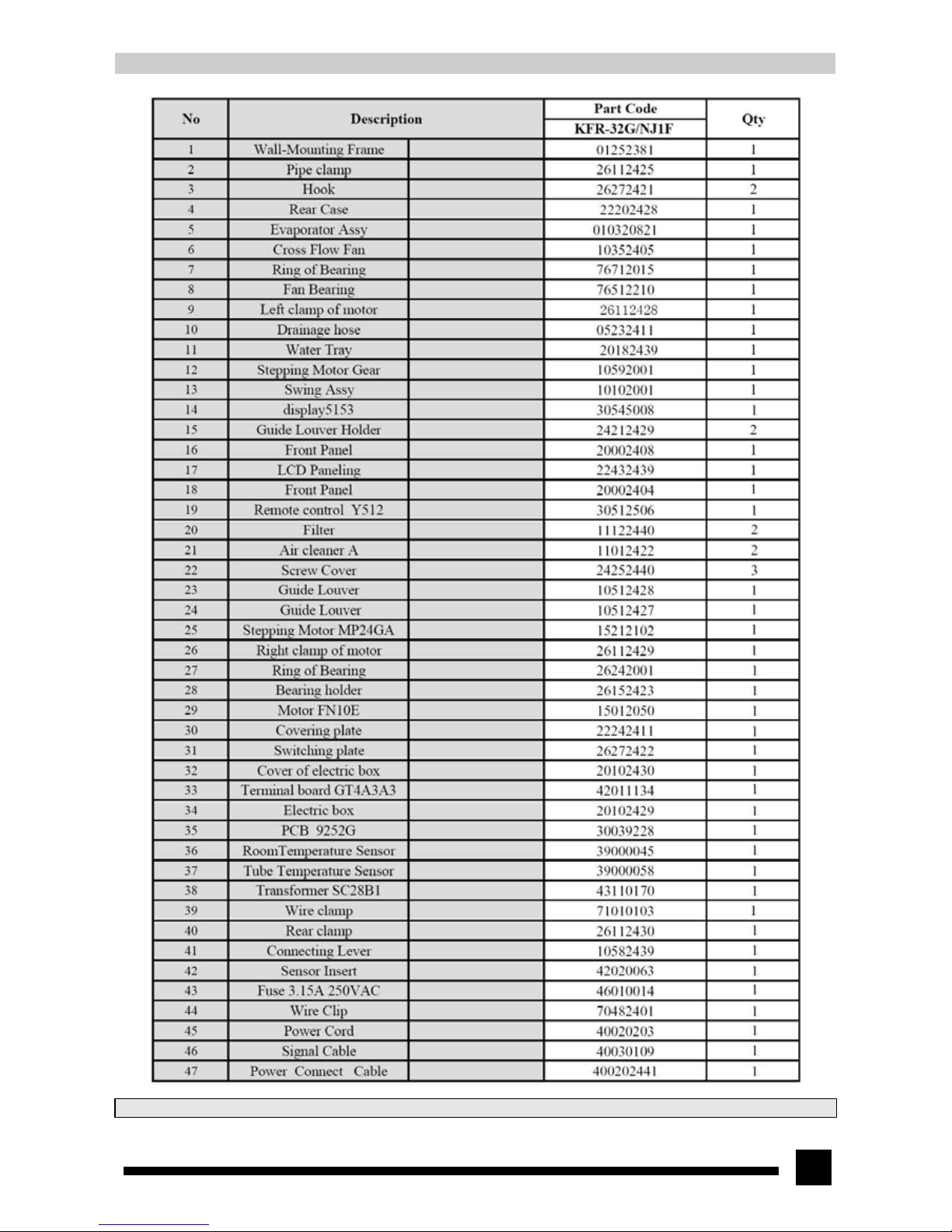
9.2 Parts and components list of indoor unit
The above date is subject to change without further notice.
Page 35
35
The above date is subject to change without further notice.
Page 36
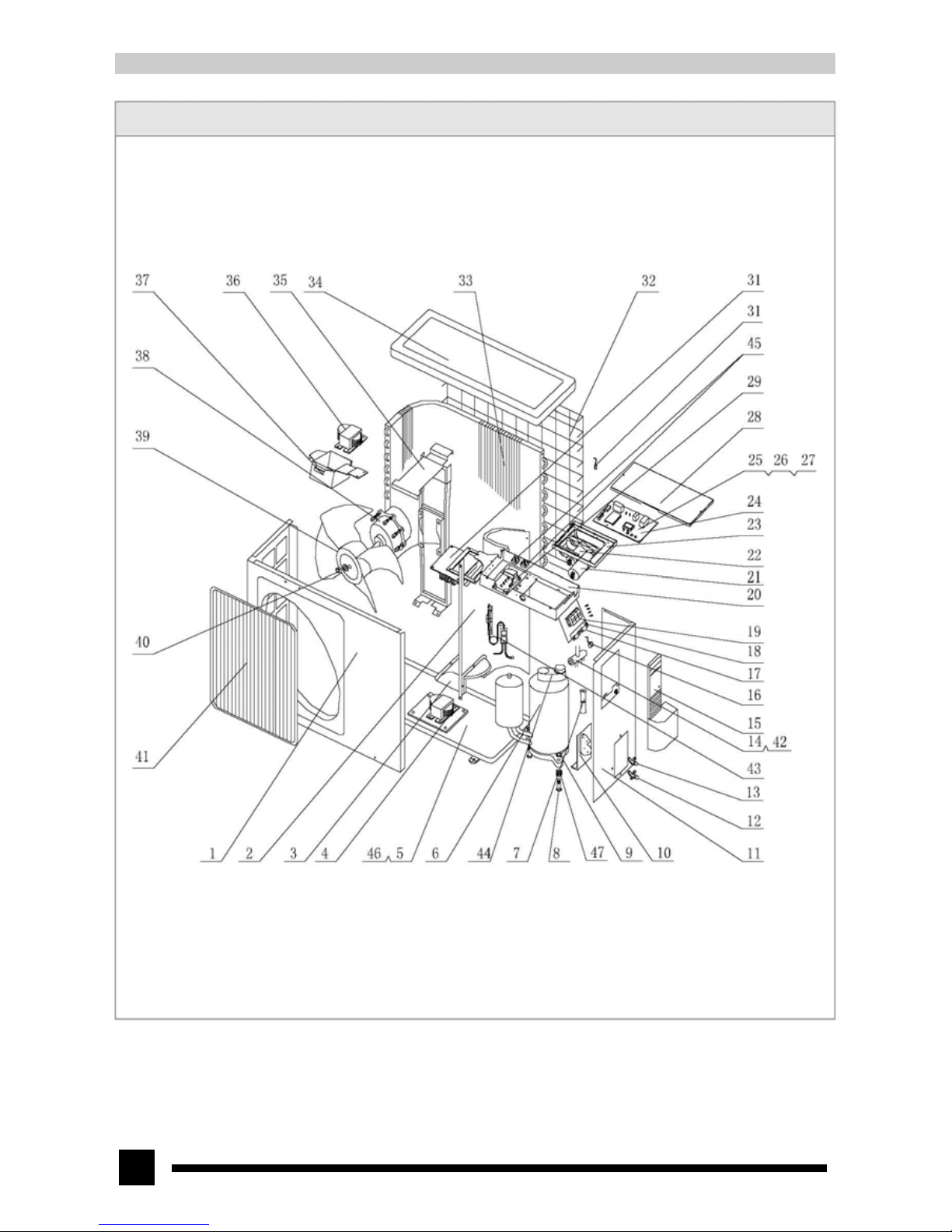
36
9.3 Explosive view of outdoor unit
Page 37
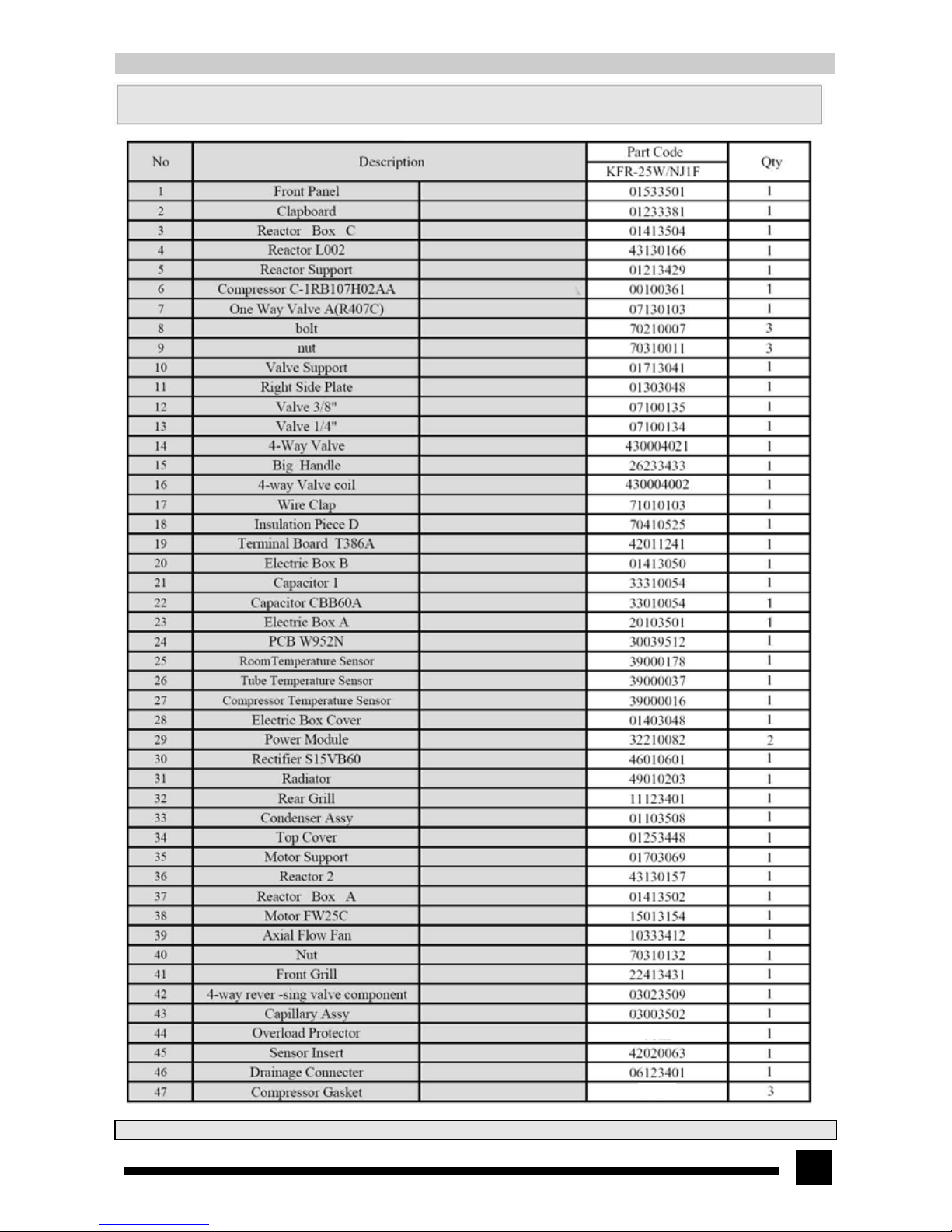
37
9.4 Parts and components list of outdoor unit
The above data is subject to change without further notice.
Built-in
Built-in
Page 38
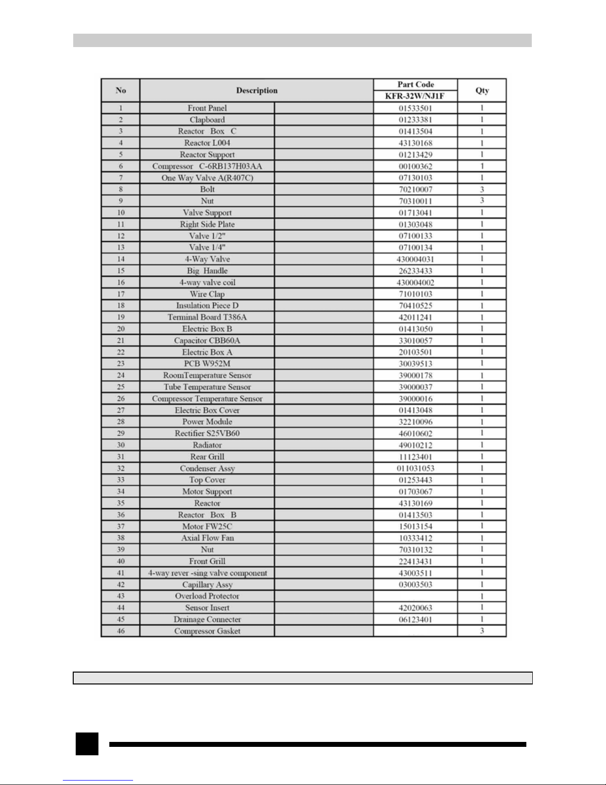
38
The above data is subject to change without further notice.
Built-in
Built-in
Page 39
39
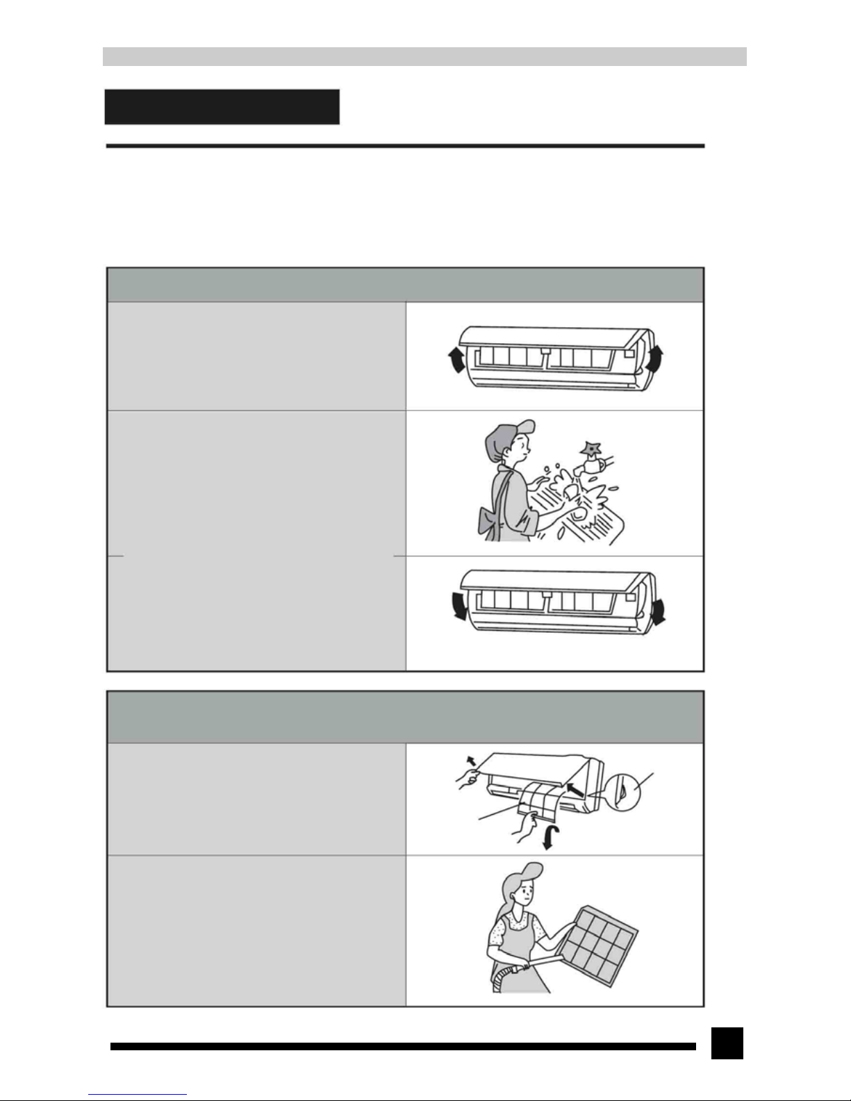
10. Care and maintenance
Warning
■ Turn power off and pull out the power plug before cleaning the air conditioner. Or it may cause electric shock.
■ Never dampen the air conditioner, which may cause electric shock. Never rinse the unit with water.
■ Use soft dry cloth or wet cloth with neutral cleanser to clean the outer case of the air conditioner
10.1 Cleaning the front panel
1.Pull the grooves on both sides of the front panel with
strength at the same time according to the arrow direction to
the position as shown in the figure and then take off the
panel.
2.Cleaning
Use soft brush, water and neutral detergent to clean the
panel and then wipe off the water and dry it.
Note:
● Do not clean the panel with hot water above 45℃ to
prevent fade or deformation.
3.Install the front panel
Put the props on both ends of the panel into the fulcrum
groove and then cover and clasp the panel cover well
according to the arrow direction.
10.2 Cleaning the air filter (once 3 months)
1. Take off the air filter
Pull the grooves on both sides of the front panel with
strength at the same time to lift up the panel to a certain
angle. Then pull the air filter downward and take it out.
2. Clean the air filter
Use vacuum cleaner or water rinsing to clean the filter. If
the air filter is very dirty (such as oil stain), use warm
water (below 45 ℃) with neutral detergent dissolved to
clean the air filter, and place it in a shady and cool place
for natural drying.
NOTE:
● Do not clean the filter with hot water above 45℃ to
prevent fade or deformation. Do not parch the wet filter
over a fire, or it will get burnt or distorted.
Groove
Air filter
Page 40
40
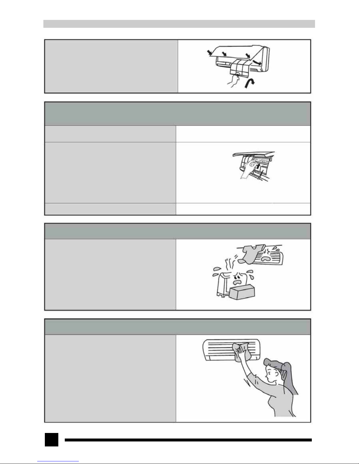
3.Install the air filter
Install the air filter properly. Let its side convex side face
you. Then cover and clasp the panel well.
10.3 Replacing the air purifier
● The air purifier is recommended for replacement once every 6 months. Please go to the special service center of Gree nearby
to purchase new air purifier for replacement.
1. Take off the air filter
Same as the first step of “Cleaning the air filter”
2.Install the air purifier
Take off the package of the air purifier screen and install the
air purifier screen into the purifier frame according to the
arrow direction.
Air purifier
Note: be careful not to hurt your hand by the evaporator
3. Install the air filter Same as the third step of “Cleaning the air filter”
10.4 Check before season begins
1. Check if there is blockage in the inlet and outlet vent of
indoor and outdoor unit.
2. Check if the grounding wire is grounded reliably.
3. Check if the batteries of the wireless remote controller has
been replaced.
4. Check if the mounting rack of outdoor unit is damaged. If
damaged, please contact special service center of Gree.
5. If the air conditioner needs to run after long-time power-off,
in order to make the air conditioner start up successfully, set
the power switch of the air conditioner at "ON" status 6
hours before it starts to run.
10.5 Maintenance after season ends
1.Clean the filter and the outer case of indoor and
outdoor unit.
2.Cut off the power of the air conditioner
3.Clean the dust and foreign substance of outdoor unit.
4.If outdoor unit is rusted, paint the rusted place to
prevent the expansion of rust.
Page 41
41
11.Installation guide
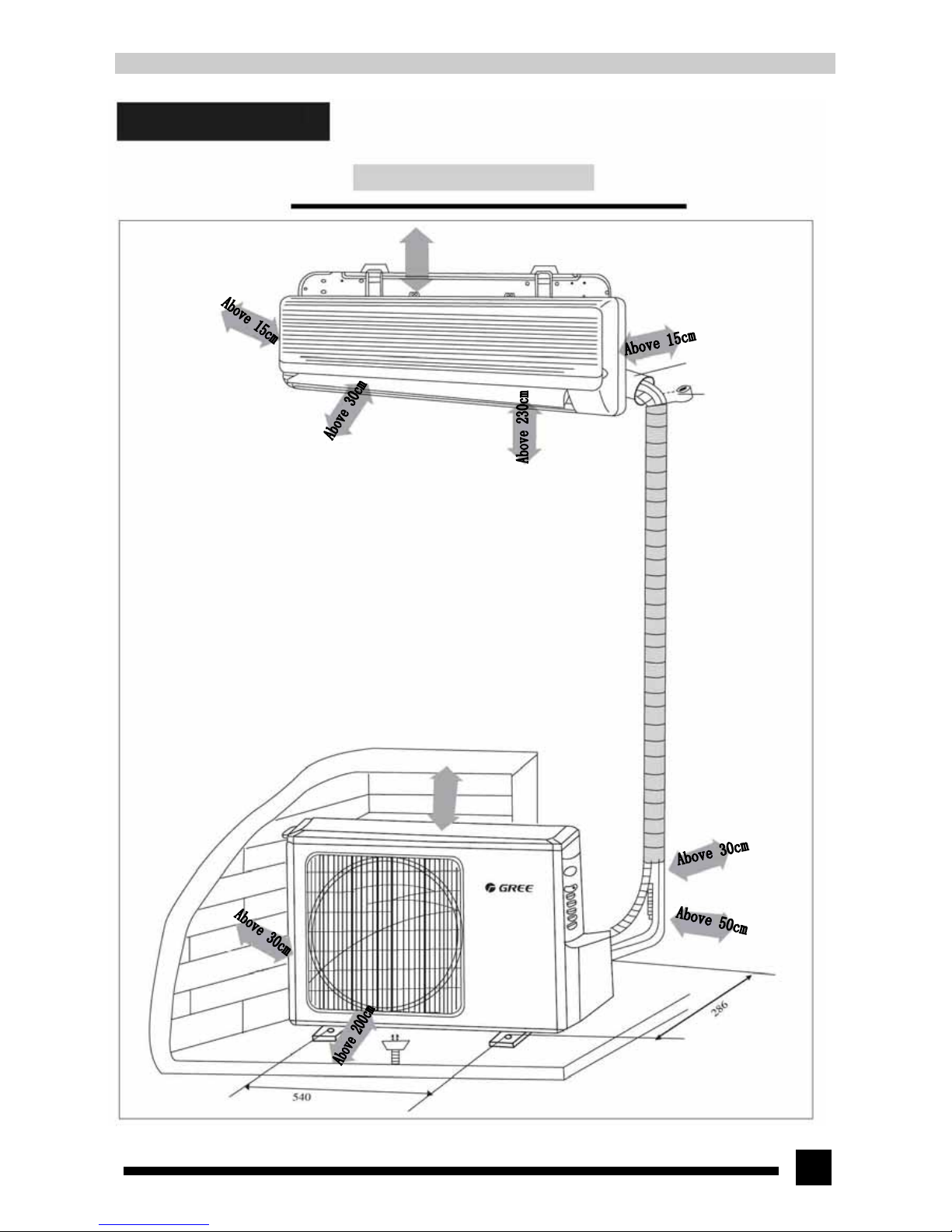
11.1 Installation dimension diagram
Distance to ceiling
Distance to wall
Distance to wall
Air outlet side Distance to floor
Important notes
1.The air conditioner must be installed by specialized personnel according to this manual
to ensure proper use.
2.Contact your local GREE special installation and maintenance department prior to
installation. Malfunction of air conditioner installed by none-special department might
be difficult to handle in time due to inconvenience of business contact.
3.Removal of the air conditioner to other location must be instructed by specialized
personnel.
Above 50cm
Wrapping tape
Distance to shelte
r
Above 50cm
Distance to wall
Distance to wall
(Fig.11-1)
Pipe hole sleeve
Page 42
42
11.2. Selecting installation location
11.2.1 Indoor unit
1. The air inlet and outlet vent should be kept far away from obstruction so that air can be blown to the entire room;
2. Select a location where it is easy to connect to the outdoor unit;
3. Select a location where it is easy to drain condensed water;
4. Keep away from heat resource, steam and flammable gas;
5. Select a location where it is possible to withstand the weight of indoor unit without increasing the running noise and
vibrations.
6. Make sure the installation of indoor unit meets requirements of the installation dimension diagram;
7. Make sure there is enough space for maintenance or repair
8. Place the unit in a place with at least 1m away from TV, Hi-fi and other home appliances;
9. Place the unit in a place where it is easy to pull out the air filters.
10. Do not place it in washing room, bathroom or location that might be caught in rain;
11 Power plug should be placed at a location where it is easy to get hold of.
11.2.2 Outdoor unit
1. Select a location where the noise and flow of air exhaust will not affect your neighbors;
2. Select a location with good ventilation to ensure good ventilation for the outdoor unit;
3. There should be no obstacles around the outdoor unit, which may block the air inlet or air outlet of the unit;
4. Installation location should be able to withstand the weight and vibration of outdoor unit and make installation work
proceed safely;
5. Select a location without leakage of inflammable or corrosive gases;
6. Make sure the installation of outdoor unit meets requirements of the installation dimension diagram.
NOTE:
Installing the air conditioner in the following locations might cause malfunction of the air conditioner. If this is
unavoidable please contact the special service center of GREE.
• Location full of machine oil
• Seaside saline and alkali districts
• Location containing sulphurate gas (such as sulphurate hotspring)
• Location with high frequency equipments, such as radio equipment, welding equipment and medical equipment.
• Location with special environmental conditions.
Page 43
43
11.3 Installing indoor unit
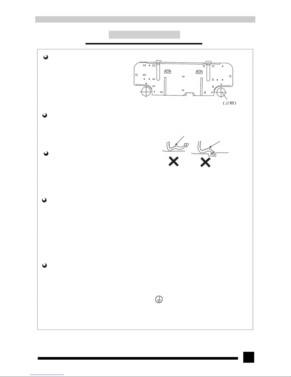
11.3.1 Installing the wall mounting plate
1 Adjust the horizontal position of the mounting plate
2. Fix the mounting plate on the wall by screws.
3. Pull the mounting plate after installation to see if it is
firm enough. The mounting plate should be able to
withstand the weight of an adult (60kg) after
installation, and the weight should be evenly shared
by each screw.
11.3.2 Installing the drainage hose
1. Drainage hose must be placed at a downward slant
for smooth drainage.
2.Do not wrench, bulge or heave the drainage hose or
flood its end into water.
11.3.3 Drilling piping hole
1.As shown in Fig.11-2, after confirming the location
of piping hole, drill a declivous hole (φ80)
2. In order to protect the pipes and cables from damage
when going through the wall, install pipe hole sleeve.
11.3.4 Installing the connecting pipe
Connect the connecting pipe with the two outlet pipes of indoor unit and tighten the joint nut of the connecting pipe. (refer to
Fig.11-6 “Installing the connecting pipe)
NOTE:
• Connect the indoor unit first and then connect the outdoor unit when connecting pipeline.
• Be careful when bending the pipe to avoid damage to the pipeline
• Do not tighten the joint nut too much, or it will cause leakage.
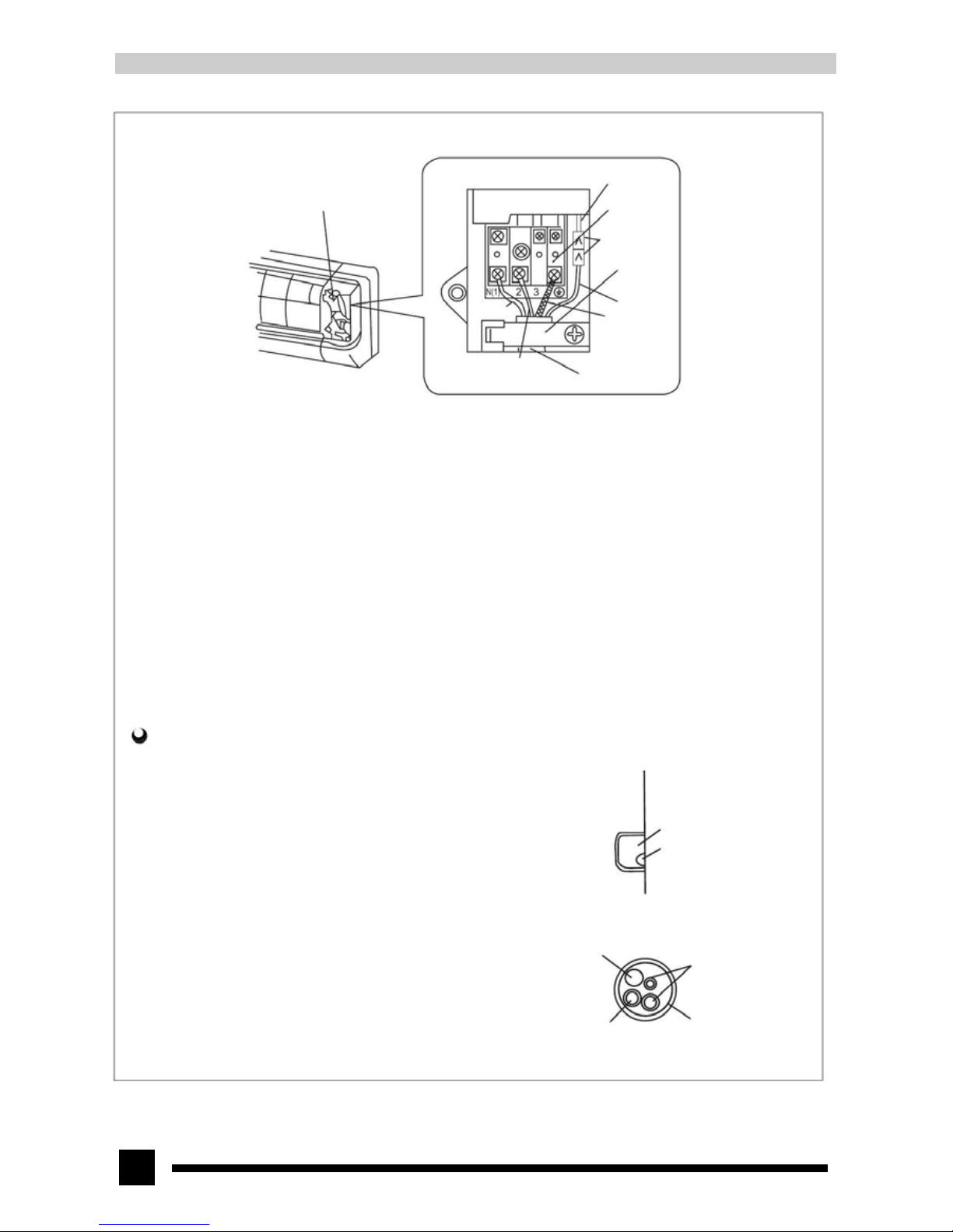
11.3.5 Electrical wiring
1. Lift the front panel upward.
2. Remove the electric box cover.
3.Wire the power connection cord through the wire hole at the back of the rear case and electric box from bottom to top.
4.Connect the blue wire of the power connection cord to the terminal “N (1)”, the brown one to terminal“2”, red one to the
connector, and the yellow-green one (i.e. grounding wire) to the “ ” terminal; (As shown in Fig.11-3)
5.Install the electric box cover to its original position.
6. Close the front panel.
(Fig.11-2)
Bulge
Wrenche
d
Do not flood its
end into water
Page 44
44
(Fig.11-3)
Notes:
● All the electrical work must be done by qualified personnel according to the local laws, regulations and this manual.
● The rated voltage and the exclusive circuit must be used.
● Electricity leakage protection switch must be installed.
● Use fuse that conforms to specification.
● The diameter of power cord should be large enough. Use the exclusive wire to replace the damage wire.
● Wiring work should conform to national standard.
11.3.6 Installing indoor unit
1. For the piping form of indoor unit, please refer to the right figure. When
piping on the left or right side, cut the tailing portion for piping left on the
base plate of the main unit, .as shown in Fig. 11-4 .
①Cut off tailing 1 when only the power cord is led out;
②Cut off tailings 1,2 when both the connection cord and wire are led out.
2. Wrap the pipe and wire well and place them through the piping hole, as
shown in Fig.11-5.
3. Hang the claw at the rear of the indoor unit to the clasp on the
wall-mounting frame and move the unit body left and right to see if it's
secured.
4. Above 2.0 meters of mounting height for indoor unit should be ensured.
Wiring cover
Signal controller
Terminal board
Connectors
Wire clip
Red
-
Brown
Power connection cord
Tailing 2
Tailing 1
(Fig. 11-4)
Power connection cord
Connecting pipe
Drainage hose
Wrapping tape
(Fig.11-5)
Page 45
45
11.4 Installing outdoor unit
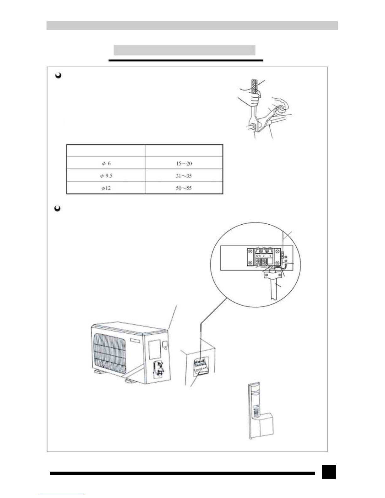
11.4.1 Installing the connecting pipe
1. Conical plug of the connecting pipe should insert properly into the
corresponding conical surface of the valve connector.
2. Tighten the nut on the connecting pipe with strength and then tighten it by
spanner, as shown in the figure
Note: Too great torque will damage the nut.
Hex nut diameter (mm) Tightening torque (N.m)
11.4.2 Wiring connection
1. Take off the big handle on the right side plate of outdoor unit
2.Disassemble the wire clip, connect the power connection cord to the
connecting terminal and fix it well. Wire distribution must match with that
of indoor unit.
3. Fix the power connection cord and signal control cable with wire clip.
Then connect the corresponding connector properly.
4. Ensure the wiring connection is fixed firmly.
5. Install the big handle assy.
Notes:
● Wrong wire connection would cause malfunction of some electric components.
● After cables are fixed, a certain degree of motion freedom should be kept for
the lead wire between the secured position and the connecting terminal.
Torque spanner
Spanner
Connecting pipe nut
Connector
(Fig.11-6)
(Red)
Red
Brown
Yellow-green
Blue
Wire clip
Power connection
cord
Screw off the tapping screws around
the top cover
Wire clip
(fixes power connection cord and signal control cable)
Big handle
(Fig.11-7)
Page 46
46
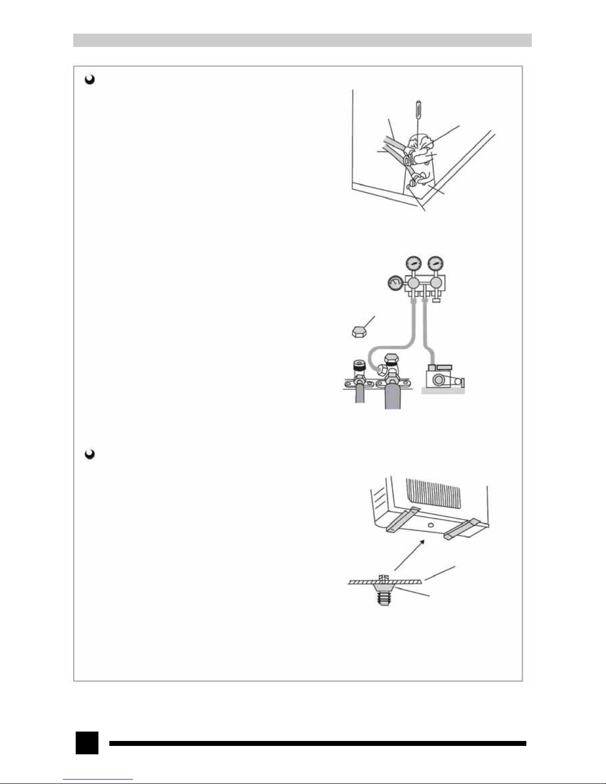
11.4.3 Vacuumizing and leakage detection
1.Take off the nut cover on the stop valve of outdoor unit.
2.Align the center of piping and tighten the conical nut with 3 or 4 turns
by hand.
3.Tighten the conical nut by spanner.
4.Take off the one-way nut cover on the liquid valve and gas valve.
5.Screw out the core of liquid valve by inner hex angle spanner.
6.Open the core of the one-way valve on the gas valve by screwdriver.
There will be gas being discharged.
7.Discharge for a while and when refrigerant gas appears, close the
one-way valve and screw up the valve cover.
8. Open the core of liquid valve and gas valve completely
9.After tightening the cover, check if there is leakage in all connecting
points by soup water or detector.
10.If possible, use vacuum pump to discharge the air in the unit through
the one-way valve.
Thin pipe Thick pipe Vacuum pump
11.4.4 Drainage of condensed water for outdoor unit
When heating, condensed water and defrosted water produced by outdoor unit
can be drained to a proper place through drainage hose.
Installing method:
Clasp and install the outdoor drainage connector into the φ25 hole on the base
plate. Then connect the drainage pipe to the drainage fitting. Condensed water
and defrosted water can be led to proper location for drainage.
(Fig.11-10)
Liquid pipe
Gas pipe
Screwdriver
One-way valve
Gas valve
Inner hex angle spanner
(Fig.11-8)
Vacuum pump
Valve bonnet
(Fig.11-9)
Chassis of
outdoor unit
Outdoor drainage
connector
Page 47
47
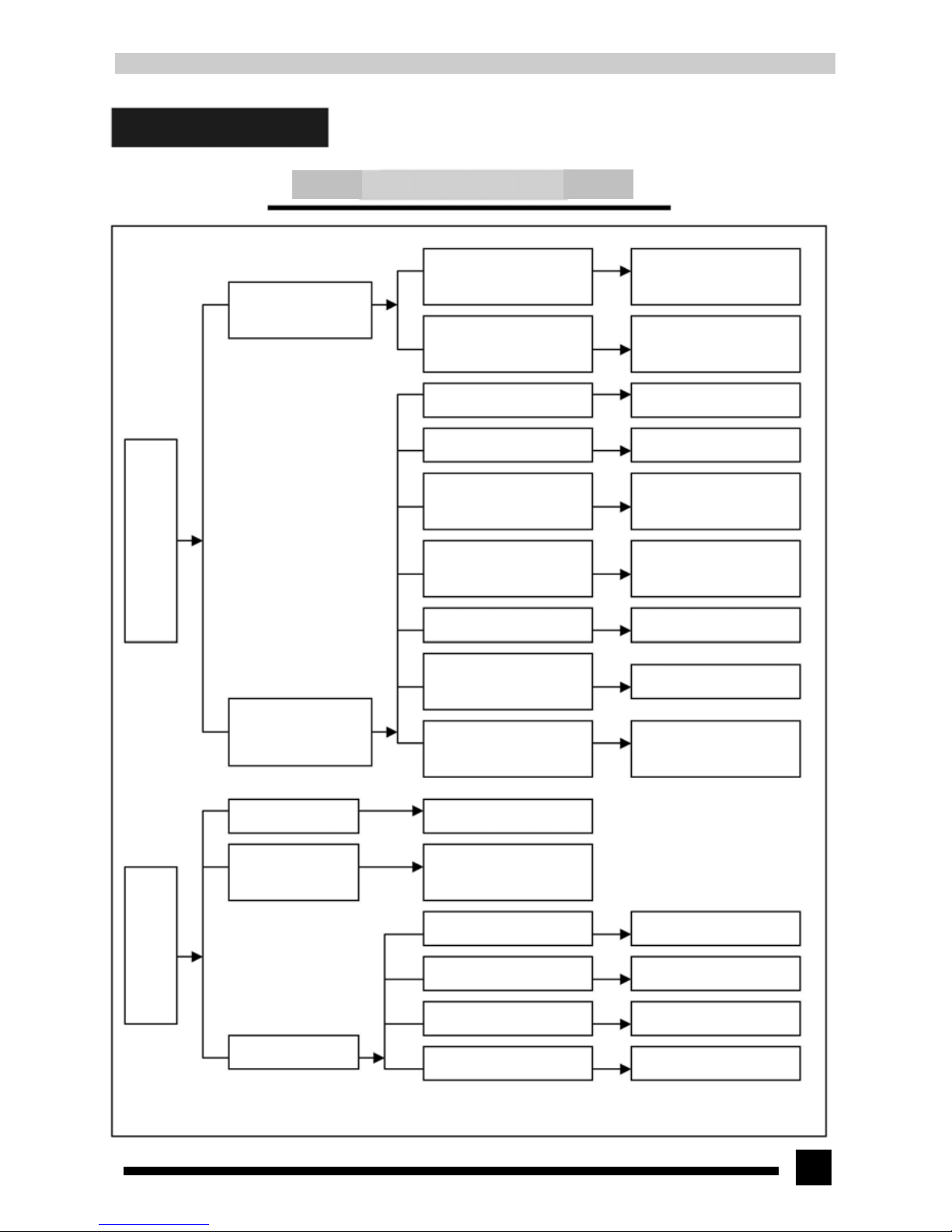
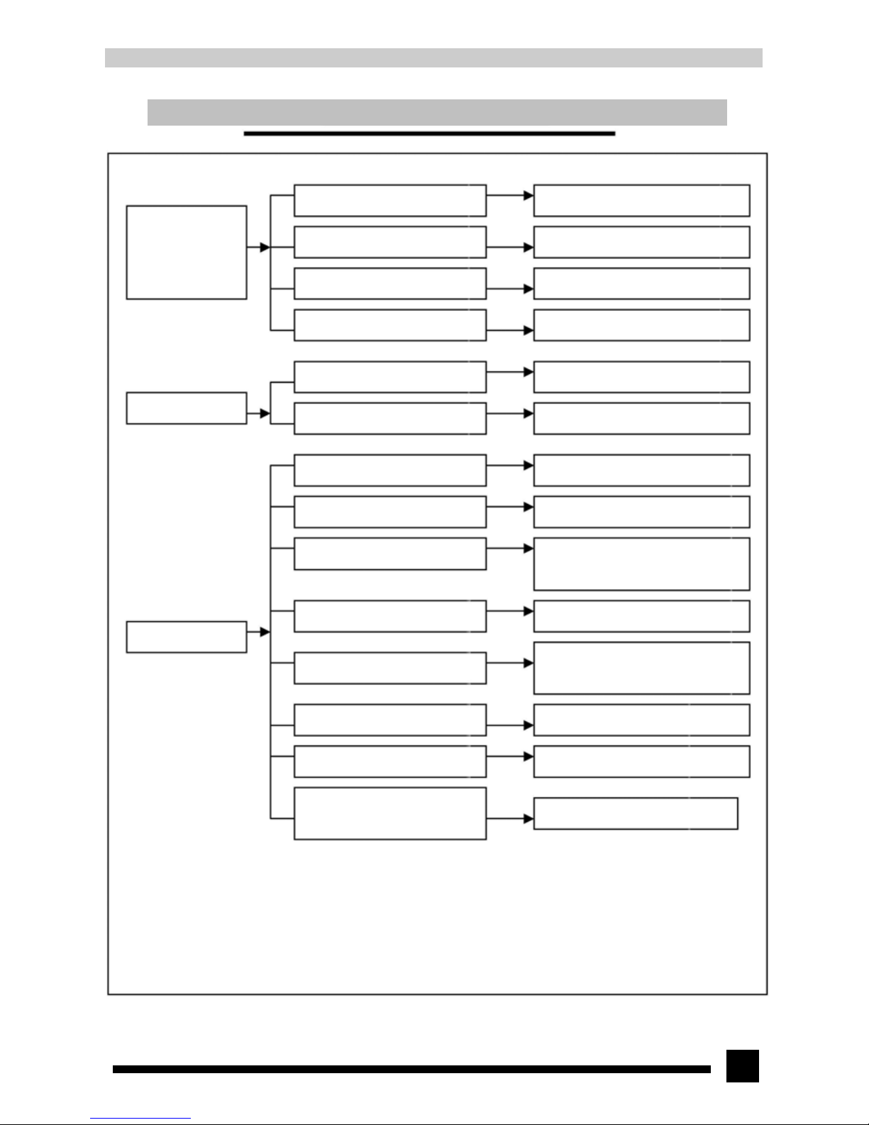
12.Malfunction analysis
Common malfunction and handling method
Breaker tripped or fuse
b
urnt out
Both indoor and outdoo
r
units cannot start up
Air conditioner cannot start up
Improper setting o
f
temperature
Whether cooling
(heating) load is proper
Malfunction o
f
refrigerant flow
Poor cooling (heating)
effect
When the breaker is set ON, i
t
will trip at once.
When the unit is turned on, the
breaker will trip in a fe
w
minutes
Measure the insulating
resistance for grounding to
confirm whether there is
electrical leaka
g
e in the unit
Check the breaker and measure
the resistance.
N
o power supply
Check power supply circuit
Transmitting malfunction of
wireless remote control
Check wireless remote control
The power plug is not o
r
poorly connected
Check and insert the plug tightly
Wrong wiring between indoo
r
and outdoor unit
Check the circuit according to
the circuit diagram and correc
t
wrong wiring
Controller fuse is burnt out
Change controller fuse
Whether connection betwee
n
strong and weak current boar
d
of controller is fir
m
Make the connecting wire firm
Whether the output wire o
f
transformer is firm, whethe
r
there is voltage output
Make the connecting wire fir
m
and check the output voltage
Adjust the set temperature
Check the estimated load o
f
cooling (heating)
Malfunction of four-way valve Replace the four-way valve
Charge refrigerant
Insufficient refrigerant volume
Replace the compressor
Malfunction of compressor
Insufficient flow volume o
f
valve
Open the valve completely
Page 48
48
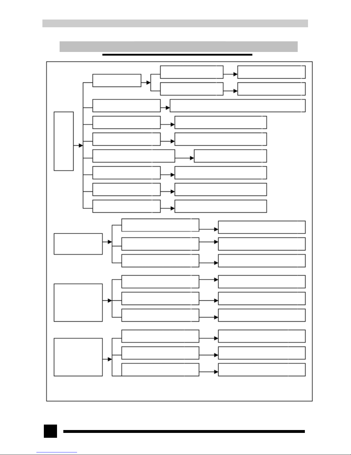
Common malfunction and handling method for air conditioner with indoor and outdoor unit
Air filters are blocked
Clean the filter
Set the fan speed to high o
r
medium speed
Fan speed was set too slow
Air circulation
is insufficient
Improper installation location fo
r
outdoor unit
Outdoor unit should be installed in a place with well
ventilation, and awning should be installed.
Poor cooling (heating) effect
Fan doesn't run whe
n
FAN mode is set
When unit is cooling o
r
heating,
both
compressor an
d
outdoor fan don't run
When unit is cooling o
r
heating, the compressor
runs but outdoor fa
n
doesn't run
Filters of indoor unit are
blocked
Clean the filters regularly
Heat exchanger of outdoo
r
unit is blocked
Clean the dust accumulated on the
surface of the heat exchanger
Leakage occurs between high an
d
low pressure inside compressor
Replace the compressor
Partial blockage of capillar
y
Replace the capillary
Leakage of refrigerant
Find out the leakage and charge refrigerant
Blockage in one-way valve o
f
outdoor unit
Replace one-way valve
Burn-out or broken wire of indoor fa
n
motor
Repair or change the fan motor
Wire according to the circuit diagram
Wrong wiring
Circuit break or damage of fan moto
r
capacitor
Replace the fan motor capacitor with the
Relay coil is wire-broken
Replace the relay
Poor contact of relay
Replace the relay
Improper setting of temperature
Adjust the set temperature
Replace the fan motor
Breakage of outdoor fan
Wrong wire connection
Wire according to the circuit diagram
Breakage of outdoor fan moto
r
capacitor
Replace the fan motor capacitor
Page 49
49
Common malfunction and handling method for air conditioner with indoor and outdoor unit
When cooling o
r
heating, outdoor fa
n
runs, but compresso
r
doesn't run.
Malfunction of compressor
Replace the compressor
Breakage of running capacitor of the
compressor
Replace the capacitor
Voltage is too low or too high
Manostat is recommended.
Wrong wiring
Wire according to the circuit diagram
Blockage or breakage of drainage hose
Replace the drainage hose
Water leakage
Wrap of refrigerant pipe connector is
not ti
g
ht enough
Re-wrap and make it tight
Abnormal sound an
d
vibration
Fan of indoor unit contacts other parts
Adjust fan location
There is foreign substance in indoor unit
Take out the foreign substance
Compressor shakes too much
Adjust support washer of the compresso
r
and tighten loose bolts
Touch of pipeline of outdoor unit
Separate the touched pipeline
Touch of inner plates
1. Tighten connecting screws
2.
Stick shock-absorbing clay between plates
Touch of outdoor unit fan blade wit
h
outer case
Adjust louver position
Replace compressor
Abnormal sound inside compressor
Abnormal electromagnetic soun
d
inside four-way valve when heating
Short circuit inside electromagnetic
valve. Replace the electromagnetic valve
 Loading...