

GReddy e-01 Instruction Manual
Instruction Manual
e-01英語版03.3.1920:28ページ1
1. Important Information
Warning!
• Installation and tuning of this product should only be
performed by a trained specialist who is very familiar with
the automobile s mechanical, electrical and fuel
management systems. If installed by an untrained person, it
may cause damage to the unit as well as the vehicle.
• When mounting this product in the vehicle, be sure the
unit does not interfere with the driver s view and normal
operation of the vehicle.
• When using soldering iron and other tools for installation,
be sure you read and understand the tool’s user manual first.
Misuse of these tools may cause injuries.
• When working on the electrical wires, make sure to
disconnect the negative terminal side of the battery on the
vehicle.
• When increasing the boost, be sure not to overboost.
Overboosting may cause damage to the engine.
• Be sure to find out what the safe boost pressure is for
your vehicle.
• GReddy Performance Products, Inc. is not responsible for
any engine damage caused by overboosting (increased
boost).
• Never tune the e-manage while the vehicle is moving.
• Never tune the e-Manage on public highway. This may
be dangerous to you as well as others on the road.
• When tuning and operating the vehicle in a garage, be
sure that the garage is equipped with a proper ventilation
system.
• After installation and tuning, be sure to clean up everything
that would interfere with the driver. Wires, tools and/or
communication cable may interfere with the driver and may
cause accidents.
Please read this instruction manual carefully and proceed with
the installation ONLY if you fully understand this manual. Make
sure to pay close attention to all the "Important!", "Warning!" and
"Caution!" messages throughout the manual.
Important!
• This product is legal for sale or use in California only on
vehicles which may never be driven on a public highway.
• This product is only for vehicles with 12V (battery) systems.
1
e-01英語版03.3.1920:28ページ2
1. Important Information
Caution!
• Improper tuning of the e-Manage may cause damage to the
engine.
• GReddy Performance Products, Inc. will not be responsible for
any damage caused by improper installation or tuning.
• Tuning should be performed only by a experienced technician
who fully understands the vehicle’s fuel management and
ignition timing requirement for the engine being tuned.
• Always use a proper air/fuel ratio meter when tuning the eManage.
• Installation of this product requires modification of the vehicle’s
electrical system.
• When making wire connections, be sure to remove the key from
the ignition, and disconnect the negative terminal of the battery.
• Never short out the system. It can damage the unit as well as
the vehicle’s electrical system.
• Read and fully understand the wiring diagram before making any
wire connection.
• When connecting the connector, push it in all the way until you
hear them click in together.
• The communication cable is not a repairable item, so please
take care of it. When disconnecting from the PC (laptop), pull
holding the connector. Never pull on the cord.
2
e-01英語版03.3.1920:28ページ3
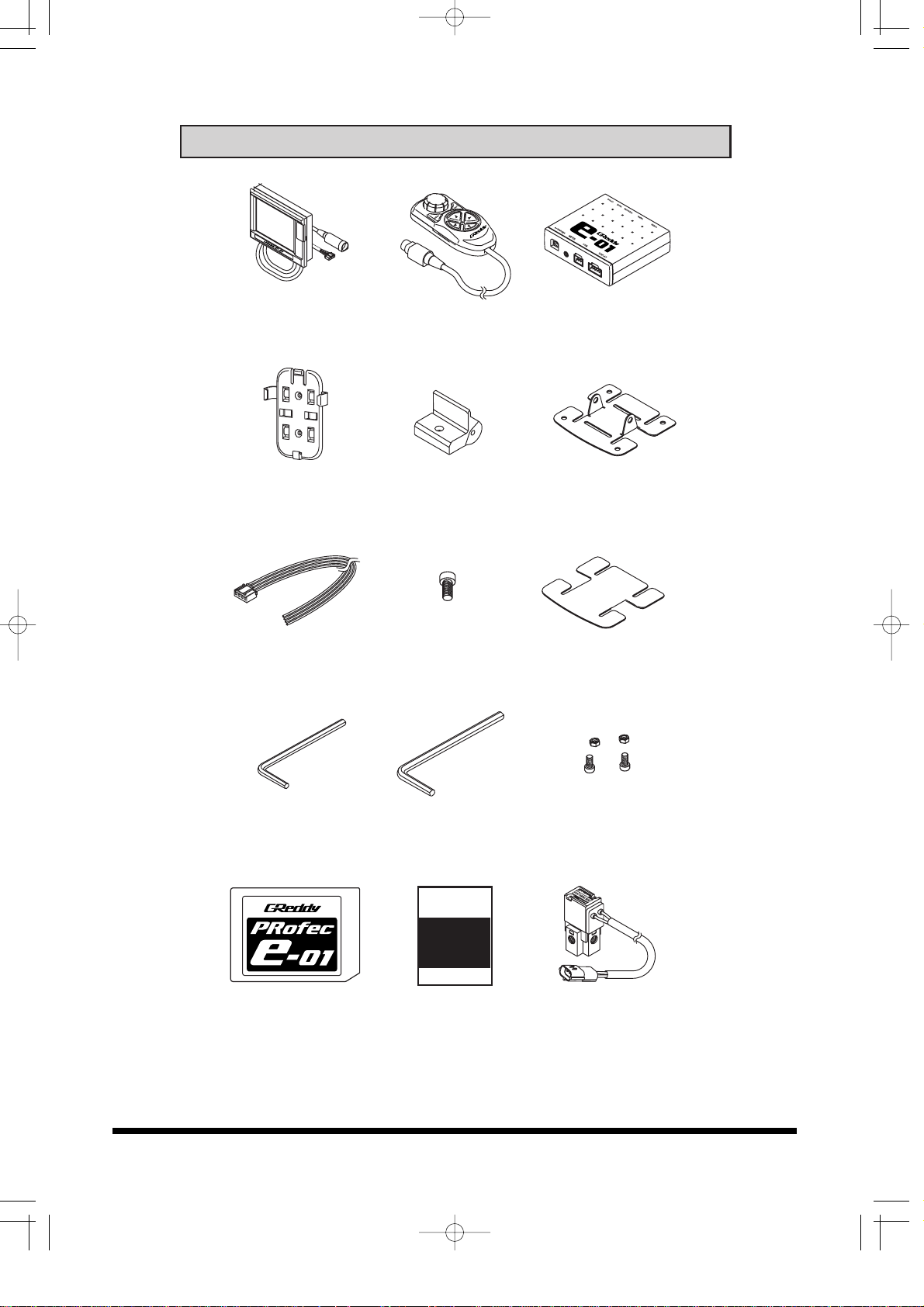
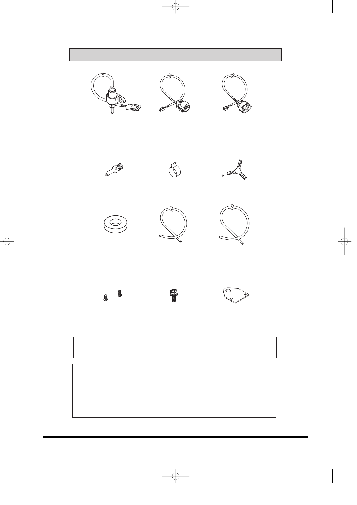
2. Parts List
3
Display unit Controller Center unit
Controller holder Display base Display bracket
Power harness 1/4 Cap bolt Double sided tape
Hex wrench (3mm) Hex wrench (5mm) M4 CAP bolt x2
M4 nut x2
SD card Instruction Manual Valve unit
e-01
e-01英語版03.3.1920:28ページ4
2. Parts List
Important!
The Display unit is packaged with the SD card already inserted.
4
Tools required for installation:
• Voltage tester • Wire cutters
• Pliers • Screw drivers (+,-)
• 10mm wrench • Solder and Soldering iron
• Electrical tape • Zip ties
Pressure sensor Valve unit harness Pressure harness
(2.5m) (2.5m)
6ø Hose fitting x2 Hose clamp Three way fitting
Rubber washer 4ø Hose (1m) 6ø Hose (1m)
M4 Bolt M6 Bolt x2 Valve bracket
e-01英語版03.3.1920:28ページ5
3. Product Features
5
• The Display unit features a large LCD with EL backlighting.
• Three large easy to read data can be displayed in real time;
such as boost pressure, rpm, etc.
• Air/fuel ratio, throttle position and vehicle speed may be
displayed with the use of an optional Signal harness
(sold separately).
• The GReddy Warning gauge data can be displayed with the
use of an optional data link cable (sold separately).
• Built-in Warning feature for all input signals; such as boost,
rpm, etc.
• Link up to e-Manage to tune and save using Standard A/B
USB cable (available through any computer supply retailer).
• Able to record up to 3 hours of data and play back on the
display.
• Controls boost up to 3kg/cm (Depending on the turbo system).
Select from Auto and Manual boost mode to boost up to a
desired pressure.
• Boost pressure may be adjusted at different rpm points to
achieve consistent boost levels.
• Uses compact high volume solenoid valve.
• Uses high quality pressure sensor.
• Able to lower the boost pressure when the warring feature is
activated.
• Boost pressure may instantly be increased by using the Over
Take Boost feature. This feature can be used with the
Optional Remote Switching System (sold separately).
Important!
Standard A/B USB cable is required in order to link the e-01 to
the e-Manage unit. This is available at any computer supply
retailer.
Fuel regulator
Display unit
2
e-01英語版03.3.1920:28ページ6
Before Installation
6
• Make sure the engine has cooled down before working under
the hood.
• Take the key out of the ignition switch and disconnect the
negative terminal of the battery.
• Before mounting the Valve unit and the Pressure sensor,
be sure the supplied vacuum hose is long enough to reach
them.
• Locate the actuator/wastegate, factory boost controlling
solenoid valve, and fuel pressure regulator or true vacuum
source before installation.
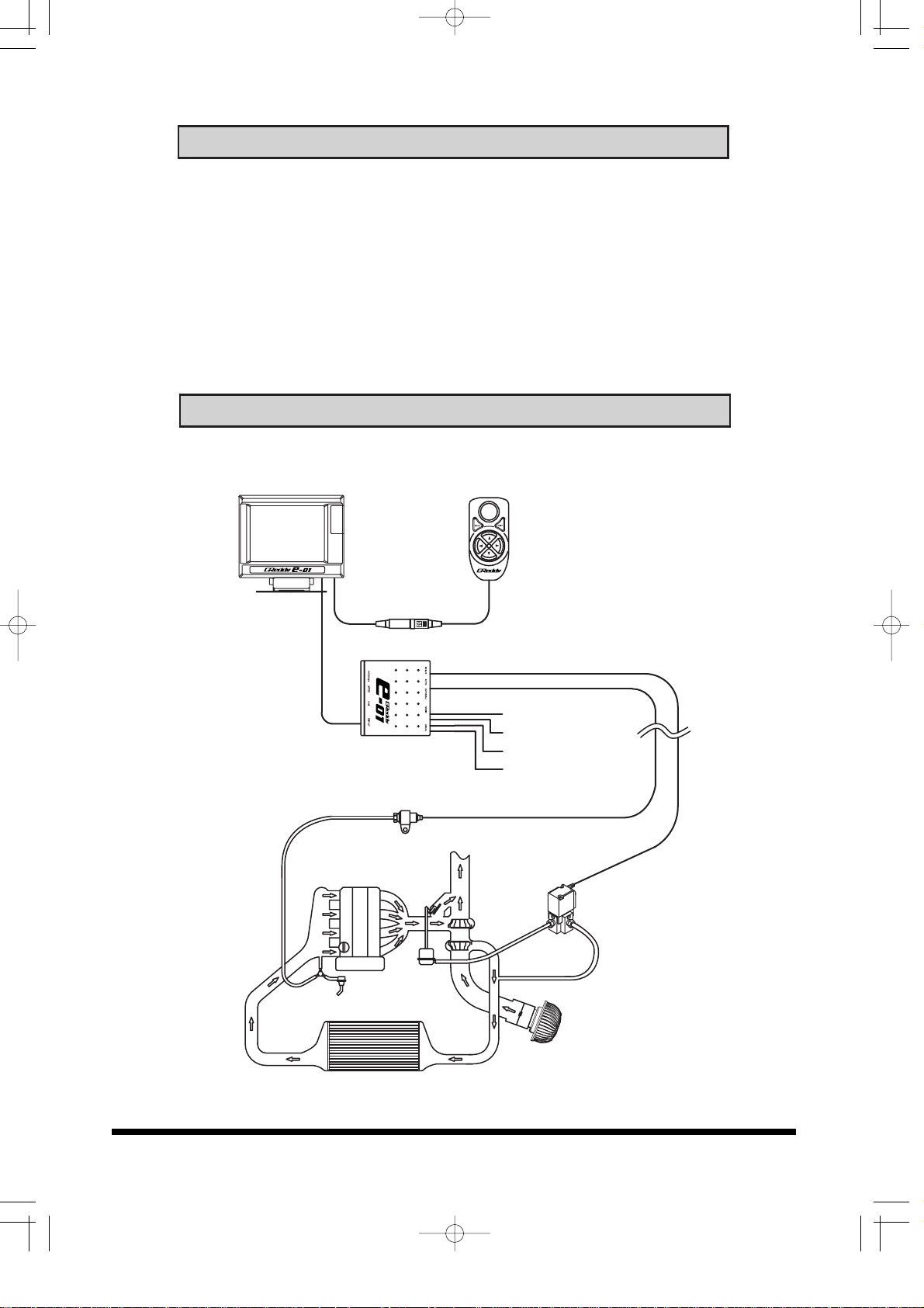
Installation Diagram
Pressure sensorPressure sensor
EngineEngine
Turbo Turbo
Valve unitValve unit
Air cleanerAir cleaner
ActuatorActuator
Fuel regulator Fuel regulator
IntercoolerIntercooler
Center unitCenter unit
ControllerController
Display unit Display unit
Option (yellow)
Ground (black)
Power 12V (red)
RPM (brown)
e-01英語版03.3.1920:28ページ7
Installation Diagram
7
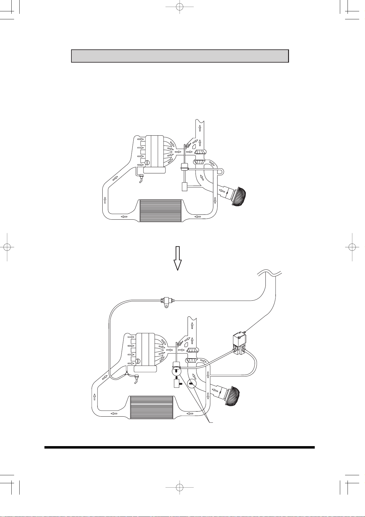
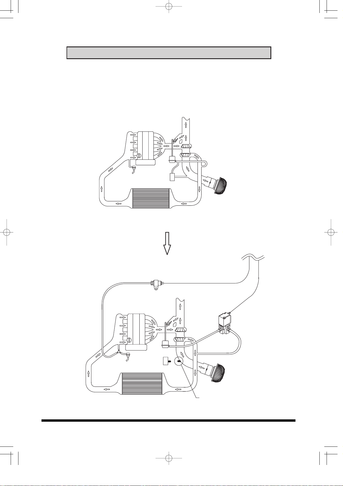
Diagram 1: Vehicle with factory boost controlling solenoid valve
Dual Port Actuator
Disconnect the connector and the vacuum lines off from the solenoid
valve and plug up the all the vacuum ports.
EngineEngine
Turbo Turbo
Air cleanerAir cleaner
IntercoolerIntercooler
solenoid valve
Before
Pressure sensor Pressure sensor
EngineEngine
Turbo Turbo
Valve unitValve unit
Air cleanerAir cleaner
IntercoolerIntercooler
solenoid valve
After
Be sure to plug up
e-01英語版03.3.1920:28ページ8
Installation Diagram
8
Diagram 2: Vehicle with factory boost controlling solenoid valve
Single port actuator
Disconnect the connector and the vacuum lines off from the solenoid
valve and plug up the all the vacuum ports.
EngineEngine
Turbo Turbo
Air cleanerAir cleaner
IntercoolerIntercooler
solenoid valve
Before
Pressure sensor Pressure sensor
EngineEngine
Turbo Turbo
Valve unitValve unit
Air cleanerAir cleaner
IntercoolerIntercooler
solenoid valve
After
Be sure to plug up
e-01英語版03.3.1920:29ページ9
Installation Diagram
9
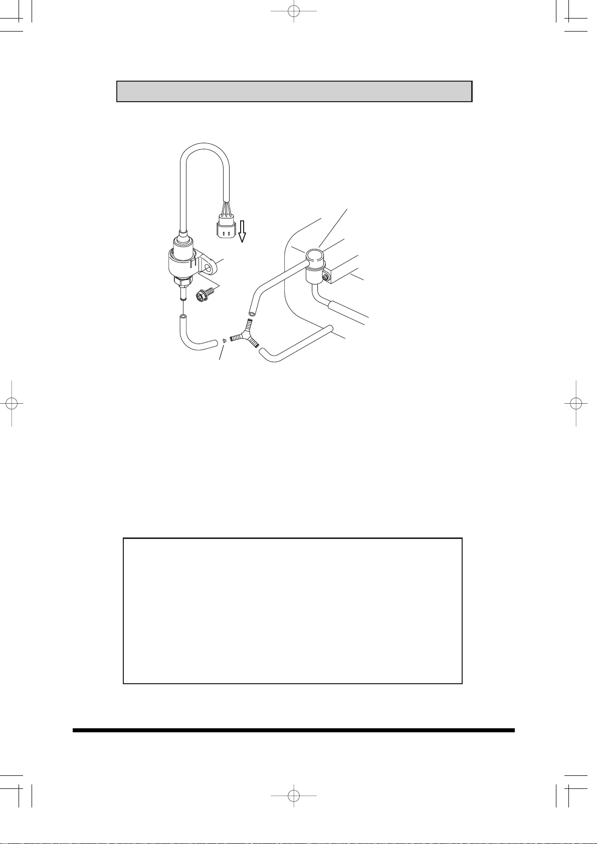
Pressure Sensor Installation
Connector must
Point Down
Fuel pressure regulator
(1) Mount the Pressure sensor to the body near the fuel regulator
using the supplied bracket and bolt.
(2) Cut the vacuum line on the fuel regulator and install the
supplied three way-fitting.
(3) Place the supplied orifice to the side that will connect the
sensor and connect the 4ø Hose from the three way fitting to
the sensor.
Important!
• Make sure that the Sensor connector is pointed down as
shown in the diagram above.
• Make sure that the sensor is securely mounted on the body.
• Av oid mounting the sensor in the hot area or where it can get wet.
• Toyota’s JZ engines and Mitsubishi’s 4G63 engine have
fuel pressure controlling solenoid valves. For these vehicles,
make sure to get pressure from the line between the intake
manifold and the solenoid.
• Make sure to secure the 4ø Hose with zip ties.
Orifice
Intake Manifold
e-01英語版03.3.1920:29ページ10
Installation Diagram
Important!
• It is very important that the Rubber washer is used when
mounting the bracket to the body.
• Mount the Valve unit in a cool area where the unit will not get
hot or wet.
• Secure all the Vacuum connections with hose clamps.
• When routing the vacuum hoses, make sure not to kink or
twist the hoses.
• Make the hoses as short as possible.
• It is normal for the Valve unit to make a clicking sound when
it is operating.
10
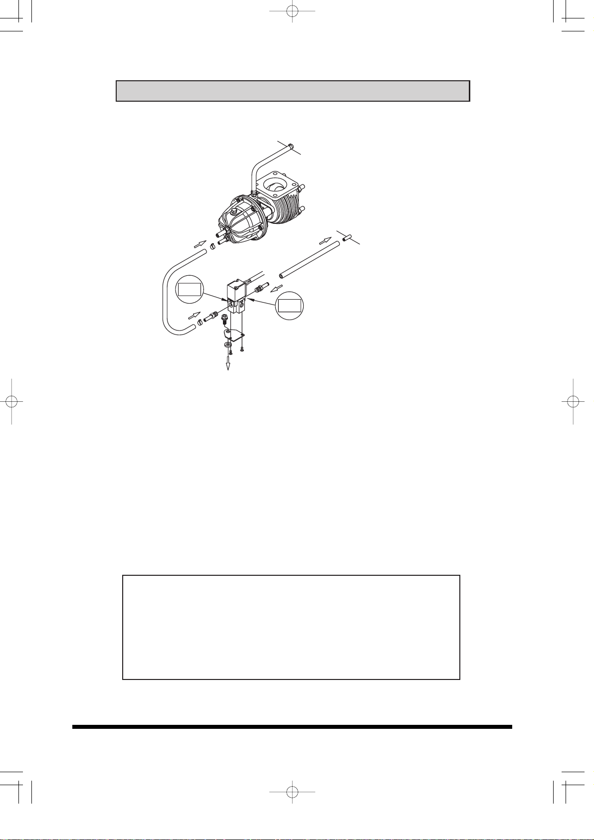
Valve Installation (Actuator type)
COM
NO
To Turbo compressor housing
or pressure source
Actuator
(1) Remove all the plastic plugs from the Valve unit
(2) Install the 6ø Hose fitting on to "NO" and "COM" port on the
Valve unit.
(3) Install the Valve bracket using the supplied M4 bolts. Then,
secure the Valve assembly to the body using the supplied
M6 Bolt and Rubber washer.
(4) Disconnect the vacuum hose connecting the compressor
housing of the turbo to the actuator at the actuator side and
connect it to the "NO" side of the Valve unit.
(5) Connect the "COM" port to the actuator using the supplied
6ø vacuum hose.
e-01英語版03.3.1920:29ページ11
Installation Diagram
11
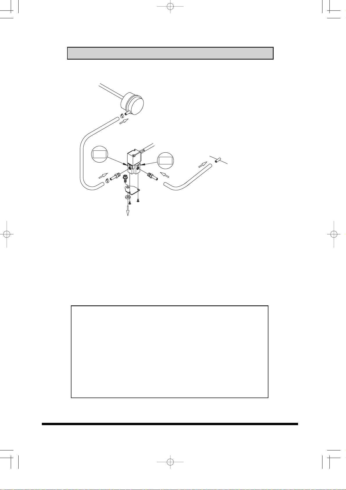
Valve Installation (External wastegate type)
(1) Install the 6ø Hose fitting onto "CN" and "COM" port on the
Valve unit.
(2) Install the Valve bracket using the supplied M4 Bolts. Then,
secure the Valve assembly to the body using the supplied
M6 Bolt and Rubber washer.
(3) Install a 6ø Hose fitting (sold separately) on the top of the
wastegate.
(4) Connect the 6ø Hose fitting that was just installed to the
"COM" port of the valve unit using the supplied 6ø Vacuum
hose.
(5) Connect the "NC" port to a good pressure source such as
the Compressor housing of a turbo using the supplied 6ø
Vacuum hose. (It is ok to tap into the same line that is going
to the bottom port on the wastegate)
Important!
• It is very important that the Rubber washer is used when
mounting the bracket to the body.
• Mount the Valve unit in a cool area where the unit will not get
hot or wet.
• It is normal for the Valve unit to make a clicking sound when
it is operating.
NC
COM
To Turbo compressor housing
or pressu source
Center unit
Display unit
e-01英語版03.3.1920:29ページ12
Wiring Procedures
Important!
• Connect the brown wire in the Power harness to the ECU rpm
signal wire. The boost controller will still operate with out this
connection, but the rpm offset feature will not work.
• Yellow wire in the Power harness is an optional output signal,
used for warning light and/or buzzer. 14V-350mA
12
(1) Connect the Pressure sensor harness and the Valve unit
harness to the Valve unit and the Pressure sensor that was
installed in the engine compartment.
(2) Route the Pressure sensor harness and Valve unit harness
through the firewall in to the passenger compartment and
connect them to the center unit.
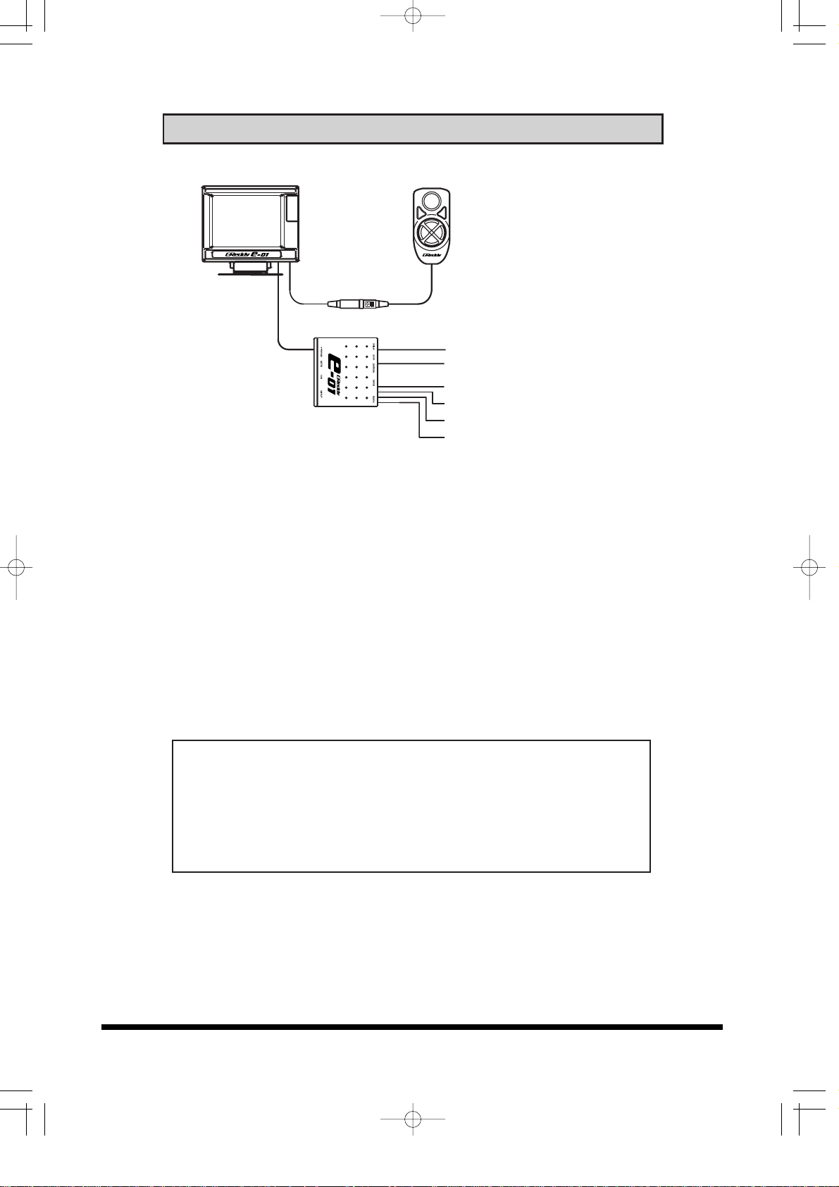
(3) Connect the Controller to the Display unit, then connect the
Display unit to the Center unit.
(4) Reconnect the battery and find 12V Ignition source with a
tester.
(5) Ground the black wire to the body. When grounding to the
body, sand or grind off any paint or rust to ensure good
contact.
Center unitCenter unit
ControllerController
Display unitDisplay unit
Option (yellow)
Valve unit harness
Pressure sensor harness
RPM signal (brown)
Ground (black)
Po wer V12(red)
e-01英語版03.3.1920:29ページ13
Mounting the Display Unit
13
• Reinstall all the parts that were removed during the installation
of this product.
• Reconnect the negative terminal of the battery.
• Make sure that all harness and hoses are secured and
properly connected and routed.
• Improper connection and routing of the harnesses and hoses
can damage the unit and the sensors, which can cause
engine damage.
• GReddy Performance Products, Inc. is not responsible for
any engine damage caused by improper installation.
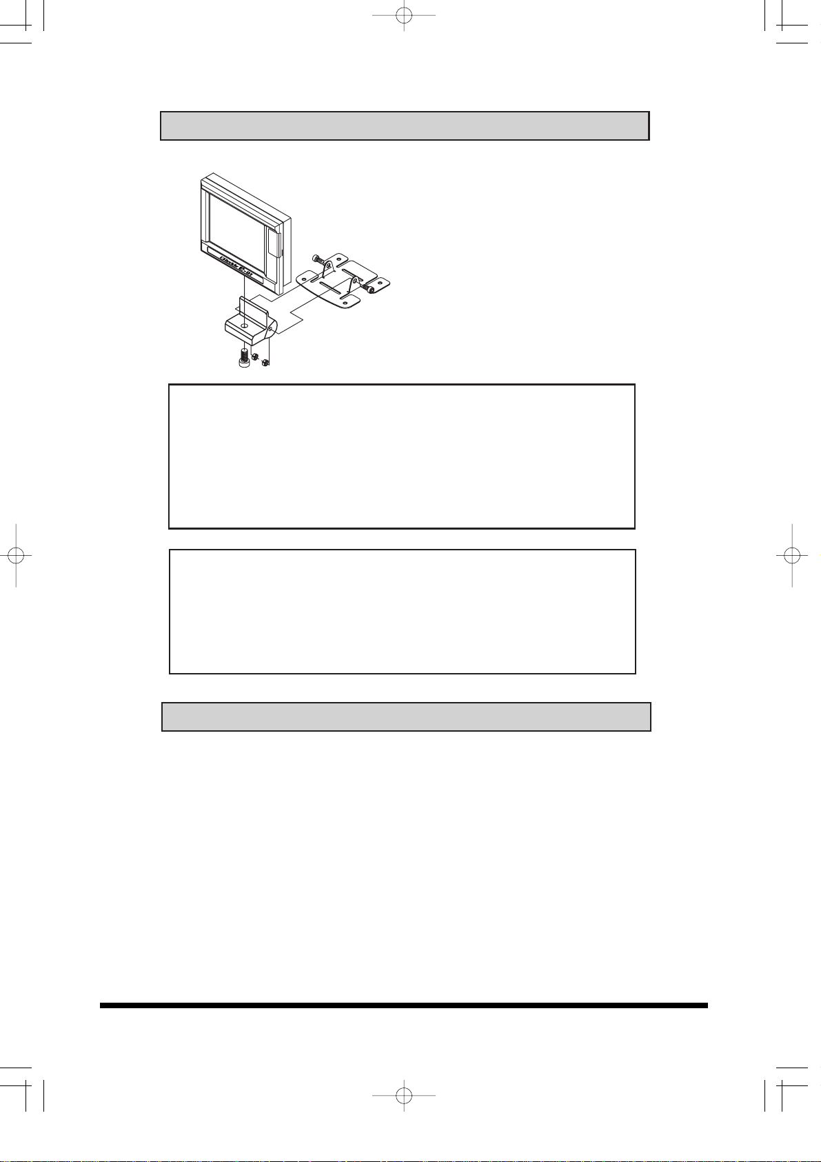
Important!
• When mounting this product in the vehicle, make sure the
unit does not interfere with the driver’s view and normal
operation of the vehicle.
• Never remove the SD card out while the unit is turned on.
This can damage the saved program in the card.
• Mount the Display unit using the
supplied base, bracket and
double-sided tape.
• Mounting surface must be free
of dirt and oil.
Caution!
• For safety, once the mounting location is determined, secure
the bracket using couple of screws so that the unit will never
fall off.
• Never install the display unit in front of the airbag system.
The unit will fly off when the air bag deploys. This can be
very dangerous.
4. After Installation inspection
e-01英語版03.3.1920:29ページ14

5. Display unit and Controller Functions
14
SET knob
• Used to change, select and confirm settings
• Used to change display mode
MENU button
• Used to go to Menu mode from display mode
• Used to cancel out during setup
SHIFT button
• Used to turn on the Over Take Boost mode.
• Used for e-manage setup
4-Way navigation button
• Scroll through menus and lists, also set
feature values
Controller features
Menu screen
Cursor
Main Menu Sub Menu
MENU button SET Knob
Setup Screen
(1) Basic Boost setup
To set each feature, scroll
down and select the desired
Main menu and Sub-menu
and make the changes in
the Setup screen.
(2) Menu screen
In the Menu screen move
the cursor using the 4-way
Navigation button and push
the Set knob to select each
feature.
(3) Setup Screen
In the Setup screen, use
the 4-way Navigation button
to move the cursor. To
change the value or setting,
turn the SET knob to
change and press the SET
knob to confirm the
changes.
(4) Press the MENU button to
return to the Menu screen
from setup screen.
e-01英語版03.3.1920:29ページ15
5. Display unit and Controller Functions
15
Controller features
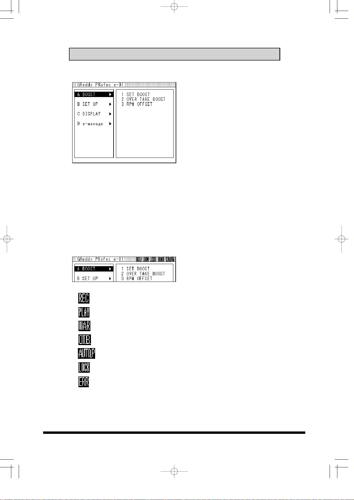
A BOOST
Used to set up boost settings
B SET UP
Used to change the initial
setting, Warning and Peak
Hold features.
Also used to setup the
optional signal harness and
Warning gauges when
installed with this unit.
C DISPLAY
This feature can display 3 input signals at real time such as
boost, rpm and Throttle position data. There are 4 different
display formats to choose from, Digital, Graph, Gauge and Bar
graph.
De-manage
Used to program the e-manage settings.
*This feature is only for vehicles equipped with e-manage
Title display description
••••displays during recording data
••••displays during data playback
••••flashes when the warning feature is activated
••••displays during Over Take Boost mode
••••displays during learning in the Auto Mode
••••displays while the unit is locked
••••displays when error has occurred.
e-01英語版03.3.1920:29ページ16
5. Display unit and Controller Functions
16
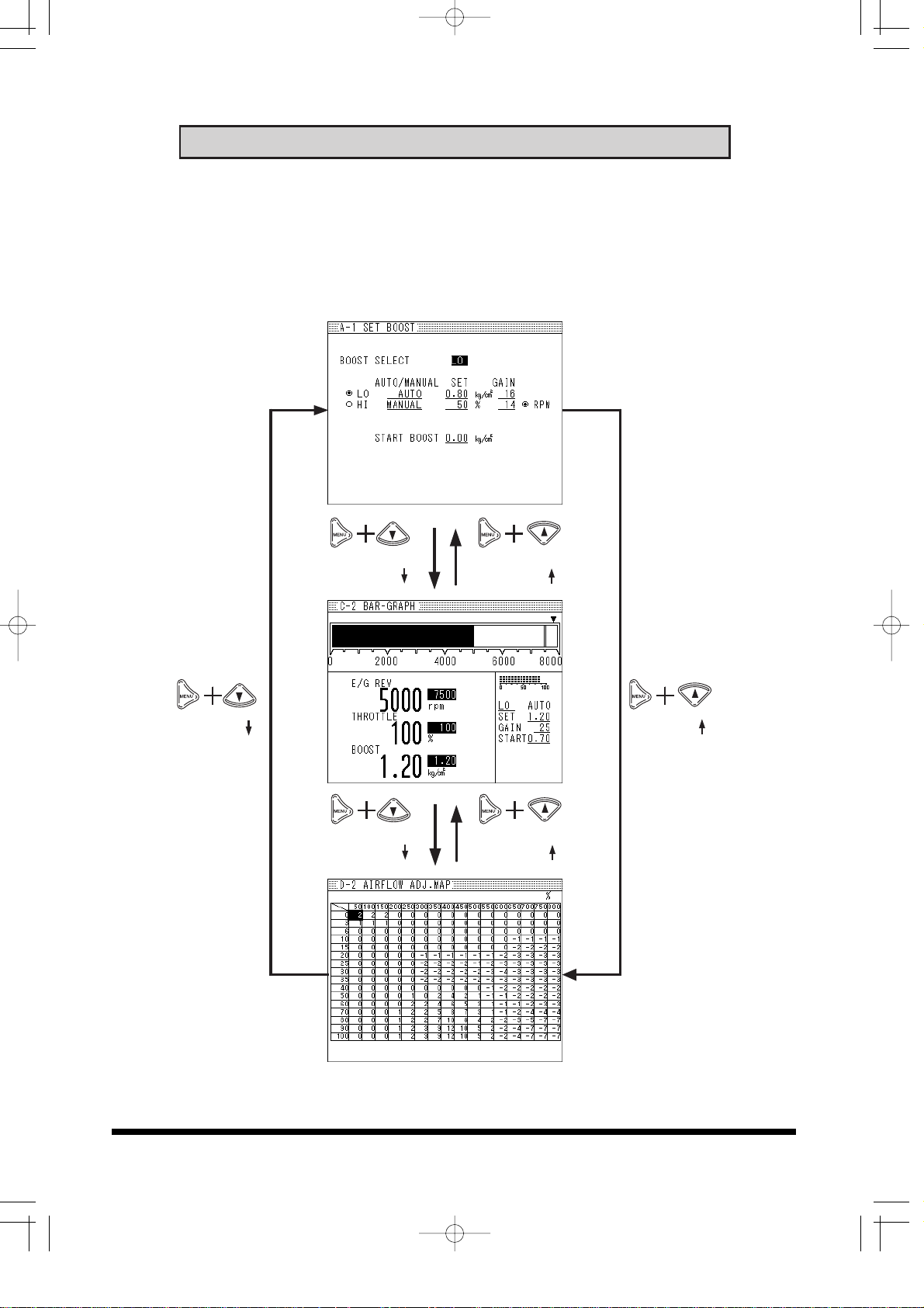
Short cut
By pressing the MENU button with the up or down key of the 4way navigation button, you can scroll to A BOOST, B DISPLAY or
C e-manage without going through the main menu screen.
MENU + MENU +
MENU + MENU +
MENU + MENU +
e-01英語版03.3.1920:29ページ17
 Loading...