

Grecom PSR-410 Owner's Manual
1
PSR-410
Advanced Base/Mobile Scanning Receiver with Object Oriented User
Interface
Owner's Manual
Please read this User's Guide before installing, setting up and using your
new product.

2
Table of Contents
Intruduction .......................................................................................5
Features ............................................................................................6
What is Object Oriented Scanning? .................................................8
A Few Things To Remember about Object Oriented Scanning .......9
About this manual ...........................................................................10
Object abbreviations used in this document ..................................10
The FCC Wants You To Know .........................................................12
Scanning Legally ............................................................................12
Getting Familiar With Your PSR-410 ...............................................14
PSR-410 Front View ........................................................................14
PSR-410 Rear View .........................................................................15
PSR-410 Included Accessories ......................................................16
Understanding the Display Icons ...................................................17
Understanding the Keypad .............................................................18
Getting Started ................................................................................20
First Time Startup ............................................................................20
Unpack the radio.............................................................................20
Base operation ................................................................................20
Attach the supplied antenna to the radio .......................................21
Mobile operation .............................................................................22
Connecting an earphone or headphones ......................................24
Connecting an Optional External Antenna .....................................25
Turn the radio on .............................................................................26
Creating Your First New Objects.....................................................27
Conventional Channel Object (CONV) ...........................................27
Talkgroup Object (TGRP) ................................................................31
Using DUPE to speed up object entry............................................36
Basic Scanning Operation ..............................................................37
Browsing Objects ............................................................................39
Advanced Startup Topics ................................................................39
About Object Numbering ................................................................40
More About Wildcard Scanning ......................................................40
Displaying Memory Usage ..............................................................41
Search Object Types .......................................................................41
Grouping Objects with Scan Lists ..................................................48

3
Finding Stored Objects Easily ........................................................52
Object Lockout ................................................................................54
Setting the Default Scan List ...........................................................57
Deleting Objects .............................................................................58
Using Multi-Site Mode On Networked Systems .............................58
LTR Home Repeater AutoMove ......................................................60
Priority Scan ....................................................................................60
Hit Counters ....................................................................................62
Audible Alarms and the ALERT LED ...............................................62
Dedicated search modes ................................................................64
Using Weather Modes ....................................................................70
Cloning Your Radio to Another PSR-410 or PSR-310 Scanner ......77
Standard Text Entry Method and QuickText ...................................78
Entering and Editing Alphanumeric Information ............................78
Using QuickText ..............................................................................79
Power-On Configuration Key Sequences .......................................80
Birdie Frequencies ..........................................................................81
Troubleshooting ..............................................................................82
Initializing Global Parameters to Factory Defaults ..........................83
Initializing the Scanner to Factory Defaults ....................................83
Care .................................................................................................85
In Case of Fault ...............................................................................85
Detailed Menu Reference ...............................................................86
GLOB Menu Reference ...................................................................86
CONV Menu Reference ..................................................................90
TGRP Menu Reference ...................................................................93
TSYS Menu Reference ....................................................................95
LMIT Menu Reference .....................................................................97
SRVC Menu Reference .................................................................100
SWPR Menu Reference ................................................................103
Appendix A - Frequency, Step and Mode Specifications .............107
Appendix B - General Specifications ............................................108
Appendix C - Finding More Information .......................................110

4
Motorola, Smartnet, Smartzone, Omnilink, ASTRO and Privacy Plus are
registered trademarks of Motorola Inc. EDACS and Pro Voice are registered
trademarks of Harris Corporation. LTR is a registered trademark of E.F.
Johnson, Inc.
© 2010 General Research of Electronics, Inc.
All Rights Reserved.
PSR-410 ADVANCED TRUNKING SCANNER
WITH OBJECT ORIENTED USER INTERFACE
Owner's Manual
Please take the time to read this manual completely
before using your new scanner.

5
Introduction
Welcome to an exciting new world of radio scanning! Recognizing that
contemporary scanning receivers are too hard to program and use, GRE's
engineers conducted extensive research to determine the functional
requirements for an entirely new scanning receiver user interface. We call
this new user interface the Object Oriented User Interface (OOUI), and it is
based on the premise that, to a hobbyist, a scanner is easiest to use if all of
the things that can be scanned are handled using common conventions for
interaction between the user and the radio, at least to the extent that this is
possible given that the ”things” that can be scanned are different from one
another in either subtle or major ways.
In this new user interface design, we call “things” that can be scanned
Scannable Objects. Simply put, a Scannable Object is defined as
something that can be scanned or monitored. Scannable Objects include
the following:
• Conventional, non-trunked radio channels
• Trunked talkgroups used on a trunked radio system
• Service searches to search for a specific radio service
• Search ranges with upper and lower limits
• Spectrum Sweeper setups with band segments that can be enabled or
disabled by the user
One of the goals of the Object Oriented User Interface is to make the
scanner as easy to use as possible. The OOUI does this by treating all
Scannable Objects the same in terms of how they are created, edited,
manipulated and grouped. Once you have learned how to create and store
a conventional channel, you know most of what you need to know to create
a trunking talkgroup, and so on.
While we have designed this radio to be the easiest scanning receiver in
its class to program and use, we encourage you to read this manual in
its entirety so that you will fully understand all of the radio's capabilities.
However, if you consider yourself to be an experienced scanning hobbyist
and are feeling adventurous, we invite you to dive right in and get started
programming your favorite “objects” into the radio.

6
Features
Upgradeable CPU Firmware - keep your radio current with enhancements
as they become available with free upgrades from www.greamerica.com!
Intuitive "Object Oriented" User Interface Design is designed for ease
of use, yet powerful enough to satisfy the most sophisticated experts.
Common data entry, browsing and control methods are used for nontrunked conventional channels, trunking talkgroups, search configurations
and Spectrum Sweeper setups. The radio grows with you - you can start
out with a small, easy to manage configuration, then expand it whenever
you need to.
Menu Driven Program mi ng With Co nt ext Sensiti ve Help - Each
menu item provides a few lines of help text that provide assistance with
programming and using the scanner.
Powerful and flexible Scan List functionality - allows you to arrange,
group and scan objects according to your preference.
Flexible Free-Form Memory Organization - memory is assigned as
objects are created using a sophisticated internal file management system.
You are not constrained to traditional bank/channel scanner memory
layouts. No memory is wasted as a result of bank/channel programming
constraints. The scanner has sufficient main memory capacity to store over
1,800 conventional channels, trunking talkgroups, search configurations
and Spectrum Sweeper objects in any combination, providing ample
capacity for more sophisticated hobbyists and professionals while keeping
the database size manageable for beginners.
SKYWARN Storm Spotter Functionality - Instant access to frequencies
used by storm spotter networks. You can monitor storm conditions as they
occur, and become aware of dangerous conditions before the media or
emergency management officials are able to announce them to the general
public.
SAME and All Hazards Weather Alerting - Your scanner can operate in
dedicated Specific Area Message Encoding (SAME) weather alerting mode,
and alert you to severe weather and other hazards in the specific area(s)
that you select, or, your scanner can check your local NOAA weather
frequency periodically, even while scanning and alert you when an All
Hazards alert occurs.
Multi-System Trunking - Scans most common trunked radio system
signaling formats, including Motorola, EDACS, and LTR.

7
LTR Home Repeater AutoMove - Takes the guesswork out of programming
LTR trunking systems when the home repeater order is not known. Enter
the LTR system frequencies in any order, and the PSR-410 will automatically
move the frequencies to the proper home repeater slots as transmissions
are received on the system.
The Subaudible Squelch Decoder - CTCSS and DCS subaudible squelch
coding is processed by the CPU. Provides fast and reliable decoding of
subaudible squelch signaling with squelch tail elimination.
Powerful Spectrum Sweeper - Quickly sweeps the scanner's frequency
ranges for transmissions from nearby sources. When a nearby active
frequency is found, the scanner automatically tunes to that frequency and
receives the traffic.
Exclusive ALERT LED - Programmable tri-color LED can be configured
to illuminate or flash when certain objects are active. Eight user-defined
colors and brightness levels can be specified from thousands of possible
combinations. Provides visual alerts when certain channels are active, e.g.,
blue can be used to signal activity on your primary police channel, red for
fire, etc.
Audible alarms - Programmable audible alarms can be configured
to sound when certain Scannable Objects are active. Can be used in
conjunction with, or separately from, the ALERT LED described above.
High Speed PC Interface - uses GRE's 100-016 USB cable in full duplex
mode at 6 times the speed of previous scanner models for PC transfer and
8 times the speed of previous models for radio to radio cloning.
Real-time Signal Strength Indicator - shows relative strength of received
signals.
Sleek, attractive case design with large speaker is well suited for
tabletop, mobile or DIN mounting.

8
What is Object Oriented Scanning?
To put it simply, Object Oriented Scanning describes a new user interface
design for scanning receivers (the Object Oriented User Interface, or OOUI).
In Object Oriented Scanning, we introduce the concept of the Scannable
Object. A Scannable Object is defined as “something that can be scanned”.
The Scannable Object concept is very important in the OOUI design. Recall
that one of the more frustrating things about current trunking scanners is
that entirely different methods of programming and interacting with the
radio are used depending on whether the user is working with trunking
talkgroups or conventional channels. A method that works with one does
not work well with the other. The user must learn two entirely different
“languages” for “talking to” the radio - one for trunking and one for
conventional, non-trunked frequencies.
What if it was possible to use the same basic “language” regardless of
whether a user is working with trunked talkgroups or conventional channels,
such that once a user has learned how to enter a conventional channel
into memory, they already know most of what they need to know to enter a
trunked talkgroup? Or, a search range, or other “Scannable Objects”? This
is how the OOUI works - the two primary Scannable Objects, talkgroups on
trunked radio systems and conventional non-trunked frequencies use the
same user interface elements.
Additionally, we include limit and service search configurations and
Spectrum Sweeper configurations as Scannable Objects. This means
that it is possible to create, edit, group, scan and delete service and limit
searches, and Sweeper configurations using the same methods that are
used when working with trunked talkgroups and conventional channels.
Object Oriented Scanning makes it very easy for newcomers to the hobby
or the radio to start off with a small collection of scannable objects and
expand their collection as needed later. Object Oriented Scanning makes
it easy to group Scannable Objects in Scan Lists, a powerful and flexible
grouping system. Object Oriented Scanning makes it easy to search for
new frequencies or talkgroups to monitor, and add them to existing or new
Scan List groups. Object Oriented Scanning makes it very easy to delete or
deactivate objects and Scan Lists that you do not want to listen to, including
a powerful temporary lockout mode that allows you to zero in on activity
associated with a specific incident, then restore your desired configuration
when the incident is over. Finally, Object Oriented Scanning makes it
exceedingly easy for the scannist to enjoy the collection of channels and
talkgroups they have programmed into the scanner, and to share them with
other scannists.

9
A Few Things To Remember about Object Oriented
Scanning
Object oriented scanning is completely different from any prior scanning
receiver technology. Accordingly, some users may find it difficult to visualize
and understand how Object Oriented Scanning works. This may be
especially true for users who have become very familiar with more recent
scanning receiver technologies.
We suggest that you keep the following “OOUI Tenets” in mind as you
proceed with your study of this manual. If you find yourself confused or
stuck about the basics of Object Oriented Scanning, it may be helpful to
review this section again.
1. The OOUI memory organization is nothing more than a large list of
"Scannable Objects".
2. A "Scannable Object" is simply "something that can be scanned",
including conventional channels, trunking talkgroups, limit searches,
service searches and Spectrum Sweeper setups.
3. In OOUI scanning, there are no "systems", "banks", "groups", "subgroups" or "ID lists". There is simply a very large collection of objects,
each with their own attributes. Scannable Objects all exist at the same
level or hierarchy within the scanner - no single type of Scannable Object
is more important than another, and Scannable Objects do not have
dependencies on or links to other Scannable Objects in order for them
to function properly.
4. The primary method of grouping the collection of objects is by mapping
them to Scan Lists. Mapping a Scannable Object to one or more Scan
Lists does not change the physical location of the object in the memory
system. Even when an object is mapped to one or more Scan Lists,
the object itself has not moved nor changed from what it is - a simple,
standalone object that is part of a larger collection.

10
About this manual
Object abbreviations used in this document
We described how your new GRE scanner utilizes an Object Oriented
User Interface in the Introduction and Overview sections of this manual.
You learned that the key components of this new user interface are the
Scannable Objects, which are, of course, “things that can be scanned”. As
you begin to use your new scanner, you will notice that the object names
are abbreviated so that they can easily fit into the 16 character LCD. (Imagine
what the radio's display would look like if “Trunking Talkgroup Object”
was spelled out in its entirety every time it was necessary to show it in the
display.)
You should take a moment and become familiar with these abbreviations
now. For consistency, the same abbreviations for the different object types
are used in the radio and here in the manual.
TGRP
TGRP is used to represent a Trunking Talkgroup Object. Trunking
Talkgroups are “virtual” channels that exist on a trunked radio system.
A trunked radio system is a radio system where a small group of radio
channels are automatically shared between a larger number of users and
user groups. This sharing of channels is managed automatically by a
special computer, called a controller, or by other specialized hardware. For
now, all you need to know is this; if you want to monitor a talkgroup on a
trunked radio system, you must store that talkgroup's parameters in a TGRP
object.
TSYS
TSYS is used to represent a Trunking System Object. A TSYS is a special
object type that is used when creating TGRP objects. A trunking talkgroup
must be associated with a specific trunked radio system in order for it to
operate. There are parameters that are associated with trunking systems,
such as the type of trunked radio system technology used, the frequencies
that the system uses to broadcast control data, etc. Instead of entering
these parameters over and over again every time you create a new TGRP
on the same trunked radio system, you create a TSYS object with all of
the system parameters, then specify that TSYS object for each TGRP you
create on the same trunked radio system. A TSYS cannot be scanned
by itself and is not considered a Scannable Object. It is a “configuration

11
object” that can be used over and over again when adding talkgroups for a
specified trunked radio system.
CONV
CONV is used to represent a Conventional Channel Object. A Conventional
Channel Object is a regular, non-trunked frequency used for radio
communications. CONV objects are used to store the parameters for
any radio channel that is not a part of a trunked system. For example,
if you want to monitor specific VHF marine channels, they should be
programmed as CONV objects. If you want to monitor your favorite amateur
radio channel, it should be stored as a CONV object. If your police or fire
department uses a channel, or channels that are not trunked, but part of a
“plain old radio system”, they should be stored as CONV objects.
LMIT
LMIT is used to represent a Search Range, or Limit Search Object. LMIT
objects contain the parameters necessary for the radio to search a range of
individual frequencies between a lower and upper limit frequency.
SRVC
SRVC is used to represent a Service Search Object. SRVC objects are
further divided into Public Safety, Aircraft, Amateur, CB, Marine, and FRS/
GMRS/MURS/DOT. SRVC objects are similar to LMIT objects, but are
preprogrammed to search all frequencies associated with the selected
service. For example, selecting the Amateur SRVC search will search
selected amateur radio frequency ranges in the VHF and UHF portions of
the radio spectrum.
SWPR
SWPR is used to represent a Spectrum Sweeper Object. SWPR objects
contain the parameters necessary for the radio to rapidly sweep a range of
radio spectrum for strong signals from nearby transmitters.

12
The FCC Wants You To Know
This equipment has been tested and found to comply with the limits for a
scanning receiver, pursuant to Part 15 of the FCC Rules. These limits are
designed to provide reasonable protection against harmful interference in
a residential installation. This equipment generates, uses and can radiate
radio frequency energy and, if not installed and used in accordance with
the instructions, may cause harmful interference to radio communications.
However, there is no guarantee that interference will not occur in a particular
installation. If this equipment does cause harmful interference to radio or
television reception, which can be determined by turning the equipment off
and on, the user is encouraged to try to correct the interference by one or
more of the following measures:
• Reorient or relocate the receiving antenna.
• Increase the separation between the equipment and receiver.
• Connect the equipment into an outlet on a circuit different from that to
which the receiver is connected.
This device complies with Part 15 of the FCC Rules. Operation is subject to
the following two conditions:
1. This device may not cause harmful interference.
2. This device must accept any interference received, including interference
that may cause undesired operation.
Scanning Legally
Your scanner covers frequencies used by many different groups including
police and fire departments, ambulance services, government agencies,
private companies, amateur radio services, military operations, pager
services, and wireline (telephone and telegraph) service providers. It is legal
to listen to almost every transmission your scanner can receive. However,
there are some transmissions you should never intentionally listen to. These
include:
• Telephone conversations (cellular, cordless, or other means of private
telephone signal transmission)
• Paging transmissions
• Any intentionally decoded scrambled or encrypted transmissions

13
According to the Electronic Communications Privacy Act (ECPA), you are
subject to fines and possible imprisonment for intentionally listening to,
using, or divulging the contents of such a transmission unless you have the
consent of a party to the communication (unless such activity is otherwise
illegal).
Th is sc ann er ha s be en de sig ned to pr event re cepti on o f ille gal
transmissions. This is done to comply with the legal requirement that
scanners be manufactured so as to not be easily modifiable to pick up
those transmissions. Do not open your scanner's case to make any
modifications that could allow it to pick up transmissions that are illegal to
monitor. Doing so could subject you to legal penalties.
We encourage responsible, legal scanner use.
In some areas, mobile use of this scanner is unlawful or requires a permit.
Check the laws in your area. It is also illegal in many areas to interfere with
the duties of public safety officials by traveling to the scene of an incident
without authorization.
14
Getting Familiar With Your PSR-410
The following illustrations are provided to help you get familiar with your
PSR-410's controls and accessories.
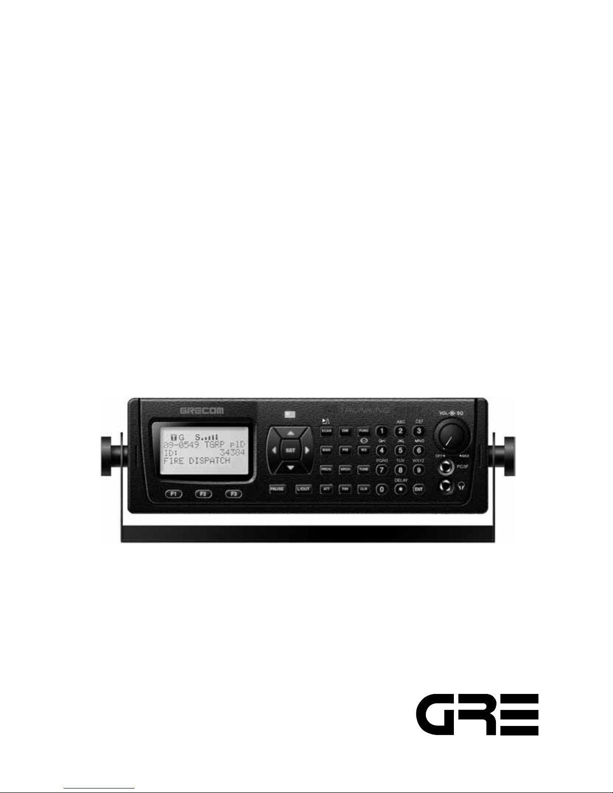
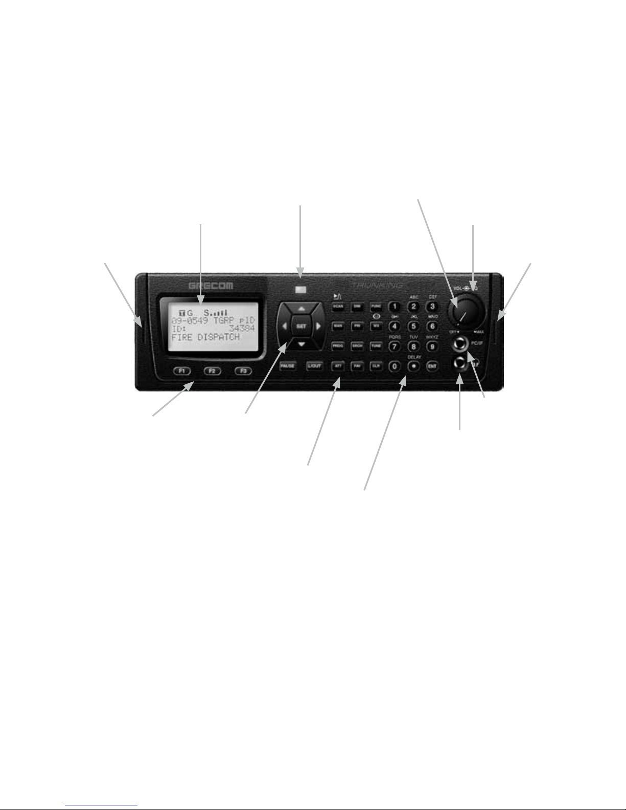
PSR-410 Front View
Figure 1 - PSR-410 front view
Alert LED
Volume Control
Squelch Control
DIN Keyslot DIN Keyslot
LCD Display
Softkeys
Five Way
Pushbutton Pad
Ooperations Key
Numeric Keypad
PC/IF Jack
Headphone Jack
15
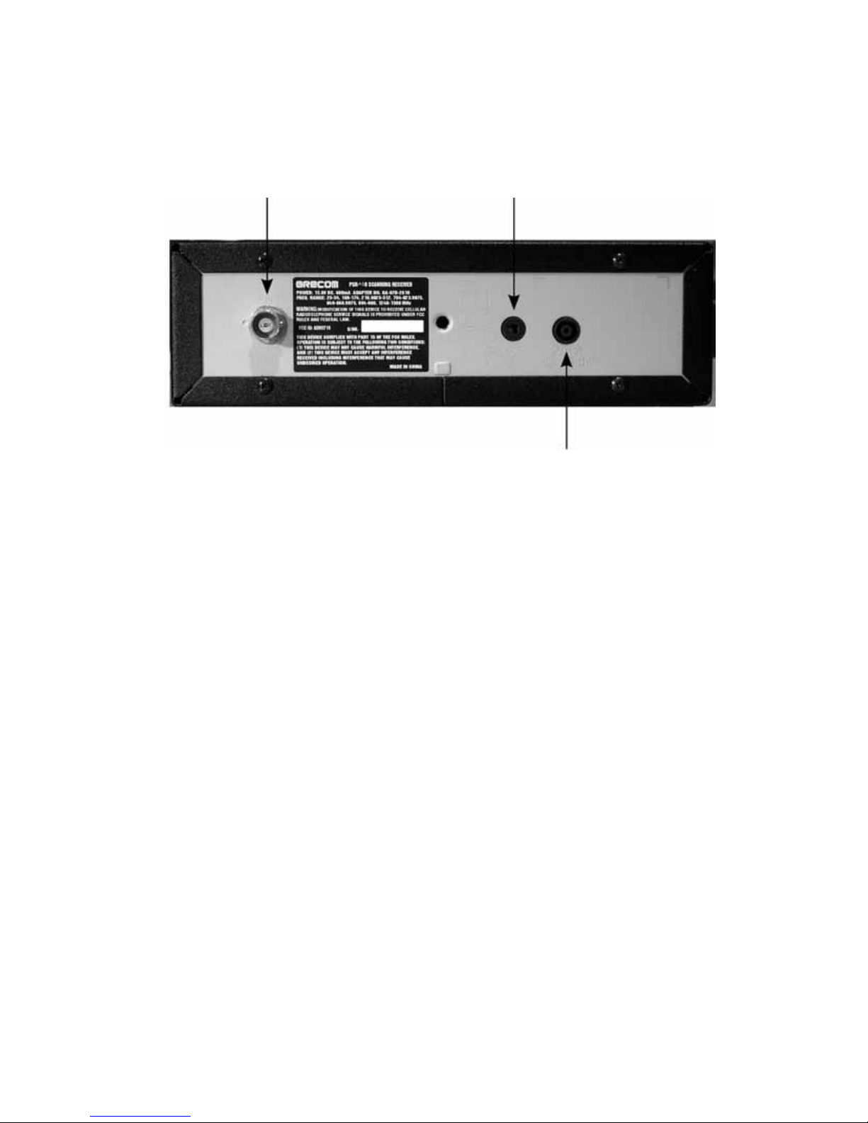
PSR-410 Rear View
Figure 2 - PSR-410 rear view
BNC Antenna Connector
External Speaker Connector
External DC Power Jack
16
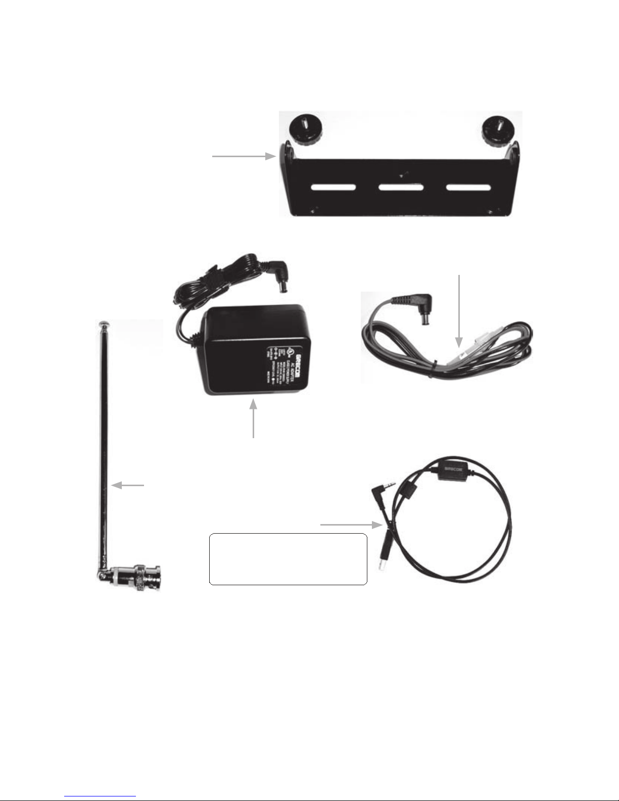
PSR-410 Included Accessories
Figure 3 - PSR-410 Included Accessories (Compact Disc not shown)
Mobile Mounting
Bracket with Rubber
Feet, Rubber Washers
and Knurled Knobs
Antenna
AC Adaptor
DC Cable
USB Cable
Note: USB cable is an optional accessory and not included in this model.
USB PC/Interface cable (Model No.:
100-016) is available on our website
(www.greamerica.com)
17
Understanding the Display Icons
Your PSR-410 features a high contrast, white backlit LCD Display to
provide important information about the status of the radio while you are
programming and using it. The LCD includes a row of icons at the top that
provides information about the status of the scanner while it is operating.
Beneath this row of icons, there are 4 rows of 16 characters each that
provide alphanumeric information for frequencies, object names, Scan List
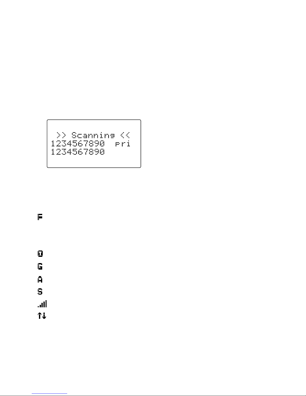
status and menu information. Figure 4 provides an example of the display
that is shown while the radio is scanning.
Figure 4 - Scanning Display
The top row of icons are defined as follows:
The Function Key (FUNC) has been pressed. FUNC acts as a “shift”
key and typically enhances in some way the action of the button that
follows it. When using FUNC, press the FUNC key first and release it,
then press the next key.
The scanner is currently receiving trunking control channel data.
The attenuator is set for Global mode.
The attenuator is currently active.
The radio's squelch circuit is open.
Signal meter indicating strength of the received signal.
Menu position and search direction indicators.
18
Understanding the Keypad
Your PSR-410 features an easy-to understand backlit keypad with 34 keys
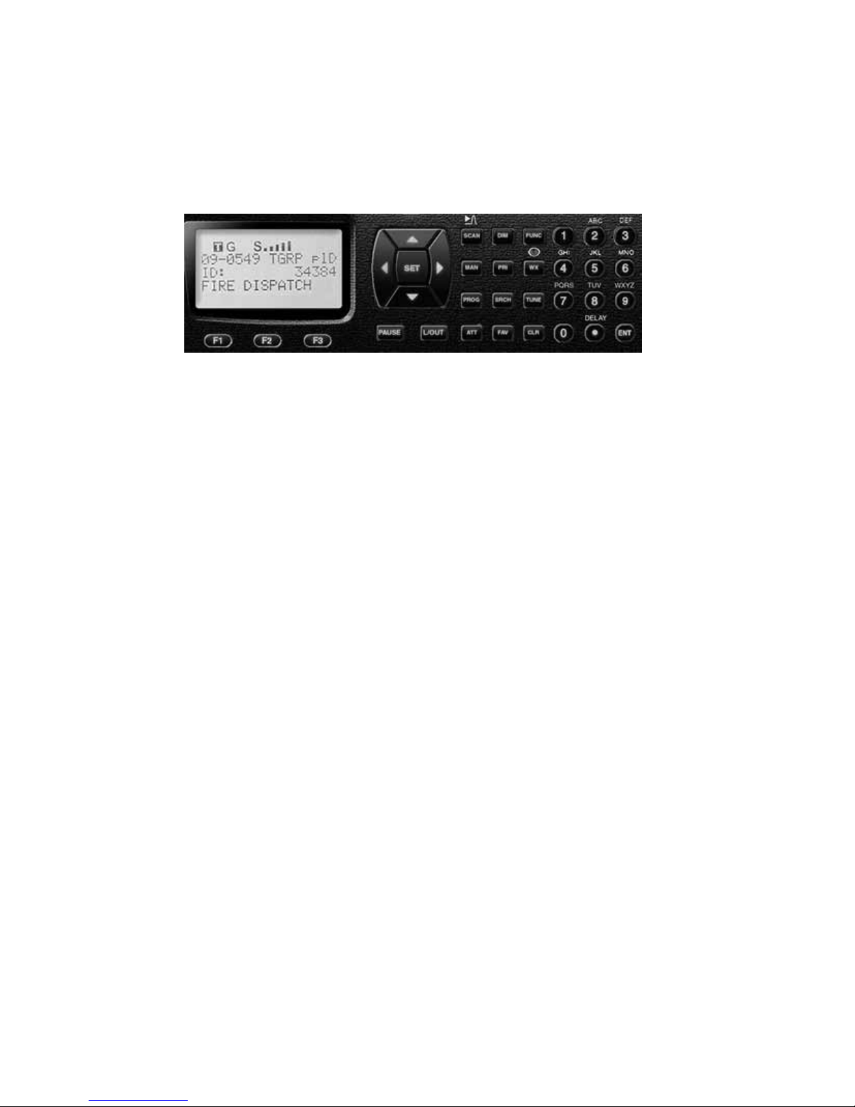
that are used to control and program the radio. Figure 5 highlights the
various keys and their basic functions.
Figure 5 - Keypad layout
Softkeys
F1, F2, F3 - activate function shown in the LCD display immediately
above the softkey.
Five Way Pushbutton Pad
5 6 3 4
keys are used for navigation while browsing objects and menus.
SEL key activates data entry fields and toggles Scan List selection in
object menus. FUNC SEL activates context sensitive help in menus.
Numeric Keypad
Used for data entry of frequencies, talkgroup IDs and alphanumeric
labels. Used while scanning, 1-9 and 0 toggle Scan Lists 1-10 on and off.
FUNC 1-9 and 0 toggle Scan Lists 11-20 on and off.
•/DELAY – Enters a decimal point (necessary when programming
frequencies), space. FUNC •/DELAY programs delay time for the
selected channel/search bank.
Operation Keys
FUNC - Activates alternate key functions. FUNC key operation is very
intuitive - typically it “amplifies” the keypress that follows it.
DIM – Controls backlight brightness.
MAN - Places scanner in Manual Mode for monitoring single objects.
SCAN - Places scanner in Scan Mode for scanning enabled objects,
FUNC SCAN launches Spectrum Sweeper.

19
TUNE - Allows direct tuning of any valid frequency, FUNC TUNE loads the
current or most recently scanned frequency into TUNE
SRCH - Dedicated Search mode for service and frequency searches
ATT - Toggles Attenuator on and off, FUNC ATT toggles Global Attenuator
mode
PRI - Toggles the Priority setting for selected or active object, FUNC PRI
toggles Priority Mode on or off for the scanner
FAV - Activates Favorites Scan Mode, FUNC FAV adds the current object to
the Favorites Scan List
WX - Activates Weather scan, FUNC WX activates Skywarn mode
PROG - Places scanner in Program Mode for editing radio-wide options,
adding new objects or editing existing objects
L/OUT - Toggles Temporary Lockout on active or selected object, FUNC L/
OUT applies permanent lockout (can be changed in the GLOB menu)
ENT - Enter key
PAUSE - Pauses scan or search operation on active object

20
Getting Started
First Time Startup
We believe that your new PSR-410 is so easy to use that scannists with
minimal experience in the hobby should be able to get up and running
in a matter of just a few minutes. If you already know the difference
between a conventional channel and a talkgroup, or a search range and
a Spectrum Sweeper, we invite you to dive right in and set the radio up
to begin scanning your first objects. If you get stuck, you can refer to
this Getting Started section, or see the relevant sections in the Detailed
Menu Reference. Otherwise, please read on and allow us to help you get
acquainted to your new scanner!
WARNING: Always protect your scanner from exposure to extreme heat or
cold temperatures.
WARNING: Your scanner is not waterproof. Do not expose it to rain,
extreme high humidity or moisture.
WARNING: The external DC power input is designed to accept 12-14.4
VDC using a tip-positive coaxial power plug. Do not connect the radio to
external power sources that are greater than 16.0 VDC. Ensure that the DC
polarity is correct before connecting your radio to an external power source.
Turn the radio off prior to connecting or disconnecting external power.
Unpack the radio
Unpack your radio carefully. Save all documentation and packing materials
in case it is necessary to return your scanner for repair.
Base operation
The mounting bracket can serve as a desktop stand when it is attached
such that it is positioned underneath the radio. You may also use the
mounting bracket indoors to attach the radio underneath a table or shelf by
installing the mounting bracket such that it is positioned on top of the radio.

21
Attach the three self-adhesive rubber feet to the bottom of the mounting
bracket in the spaces provided. The rubber feet help prevent sliding on
smooth surfaces, and will help prevent scratching of your desk or tabletop.
Do not use the rubber feet if you plan to attach the mounting bracket to a
fixed surface with screws.
Attach the two self-adhesive rubber washers to the inside of the mounting
bracket sides, over the holes that are used when attaching the bracket to
the scanner’s side holes. Be sure to align the holes in the washer carefully
with the holes in the mounting bracket. The rubber washers help protect the
scanner’s case from scratches.
Slide the scanner carefully into the mounting bracket assembly, and use
the two provided knurled knobs to secure the scanner within the mounting
bracket.
Connect the supplied DC power supply to your wall outlet. Connect the
coaxial power plug to the radio.
WARNING
To prevent electric shock, do not use the AC adaptor’s polarized plug with
an extension cord, receptacle, or other outlet unless you can fully insert the
blades to prevent blade exposure.
Caution
• You must use a supplied AC adaptor.
• The correct orientation for the enclosed power adaptor is in a vertical or
floor-mount position.
Note: Plug the adaptor into an easily accessible power outlet located near
the equipment.
Attach the supplied antenna to the radio
Your scanner’s sensitivity to various frequencies depends on its location
and the antenna’s length. For best reception, adjust the antenna’s length as
follows:

22
Frequency Antenna Length
25-54 MHz Extend fully
108-174 MHz Extend 4 segments
216-225 MHz Extend 3 segments
225-406 MHz Extend 2 segments
406-1300 MHz Collapse fully
Note: If desired, you may also connect an external base station antenna
feedline equipped with a BNC male connector to the antenna connector.
Please refer to the section entitled “Connecting an Optional External
Antenna” below for important instructions and warnings.
Mobile operation
By attaching the mounting bracket such that it is located on top of the radio,
it is possible to mount the radio underneath your vehicle’s dashboard, or in
any other mounting location where the radio will be suspended from above.
You may also use the mounting bracket such that it is located underneath
of the radio, which makes it possible to mount the radio on top of any flat
surface in your vehicle.
Your PSR-410 is also designed to fit into a DIN-E compatible sleeve,
which makes it easy to mount the radio in an existing radio or CD player
dashboard opening. An optional DIN-E installation kit can be purchased
form GRE at:
http://www.greamerica.com
Note: In certain cases, installation of mobile communications electronics in
modern automobiles requires specialized tools, training, and experience.
If in doubt, seek assistance from a local car audio electronics installation
shop, or a local two-way radio dealer.
Select a mounting location that does not interfere with visibility while driving.
Use caution not to select a location that may interfere with the deployment
of your vehicle’s air bags. It is extremely important not to mount this or
any other equipment in locations where deployment of the air bags may
cause the equipment to be propelled towards the vehicle’s passengers. If
necessary, seek advice from your automotive dealer or service shop.
Use the mounting bracket as a template to mark the locations for the two
mounting screws.

23
At the marked locations, drill holes that are slightly smaller than the screws.
Use caution not to damage wiring or components that are located behind
the mounting surface.
Using the provided screws and lock washers, attach the mounting bracket
to your vehicle.
Attach the two self-adhesive rubber washers to the inside of the mounting
bracket sides, over the holes that are used when attaching the bracket to
the scanner’s side holes. The rubber washers help protect the scanner’s
case from scratches.
Slide the scanner into the mounting bracket assembly, and use the two
provided knurled knobs to secure the scanner within the mounting bracket.
Connect the supplied DC power cable to a power source in your vehicles
as follows:
Disconnect the cable from the negative (-) terminal of your vehicle’s battery
prior to attempting any connections to your vehicle’s electrical system.
Note: Disconnecting your battery may reset certain devices in your vehicle,
such as automotive audio systems, navigation systems, alarm systems,
keyless entry systems, etc.
Route the supplied DC power cord between a power source and the
mounting location for your scanner.
Ground the black wire of the supplied DC power cord to your vehicle’s
chassis drilling a small hole in a metal frame member underneath your
dashboard and using a small sheet metal screw to secure the black wire to
the frame.
Note: Be sure the grounding screw makes complete contact with the metal
frame of your vehicle.
Connect the red wire of the supplied DC power cord to a voltage source
that turns on and off with ignition switch, such as a spare accessory
terminal in your vehicle’s fuse box.
Insert the coaxial power plug into the DC 13.8V jack on the rear of the
radio.
Reconnect the cable to the negative (-) terminal of your vehicle’s battery.
For temporary installations, you may wish to use a cigarette lighter cable to
power your scanner.

24
To power your scanner from a 12V power source in your vehicle, such as
cigarette-lighter socket, you need a 12V, at least 600mA DC with 7.75mm
outer/1.7mm inner plug cigarette-lighter adaptor (not supplied).
Insert the adaptor’s barrel plug into the scanner’s DC 13.8V jack.
Plug the adaptor’s other end into your vehicle’s cigarette lighter or power
socket.
Warning: You must use a power source that supplies 12-14.4 VDC and is
rated for 600mA. Its center tip must be set to positive and its plug must fit
the scanner’s DC 13.8V jack. The supplied DC power adaptor meets these
specifications. Using a DC adaptor that does not meet these specifications
could damage the scanner or the adaptor.
Warning: The DC power cord is equipped with an inline fuse. This fuse
protects your scanner and your vehicle from damage in case of equipment
malfunction or a short circuit. Do not remove the inline fuse holder from the
DC power cord. If the fuse blows, replace it with a 2A fuse and apply power
again. If the fuse blows again, check all wiring for short circuits, and check
the radio for a malfunction.
Note: When your radio is connected to your vehicle’s DC power system,
you may hear noise from your vehicle’s electrical system in the radio’s
speaker. Consult with a local electronics supply store to obtain a filter that
will reduce or eliminate this noise.
Connecting an earphone or headphones
For private listening, you can plug an 1/8” (3.5mm) mini-plug earphone or
headphones (not supplied), into the headphone jack on the from panel.
This automatically disconnects the internal speaker.
Connecting an Extension Speaker
In a noisy areas, or you install the scanner into your dashboard, extension
speaker (not supplied) might provide more comfortable listening. Plug the
speaker cable’s 1/8 inch (3.5mm) mini-plug into your scanner’s EXT-SP
jack, located on the rear panel of the radio.

25
Listening Safely
To protect your hearing, follow these guidelines when you use headphones.
Do not connect headphones to the external speaker jack located on the
rear panel of the radio.
Set the volume to zero before putting on headphones. With the headphones
on, adjust the volume to a comfortable level.
Avoid increasing the volume once you set it. Over time, your sensitivity to
a volume level decreases, so volume levels that do not cause discomfort
might damage your hearing.
Avoid or limit listening at high volume levels. Prolonged exposure to high
volume levels can cause permanent hearing loss.
Traffic Safety
Wearing headphones while operating a motor vehicle or riding a bicycle
can create a traffic hazard and is illegal in most areas.
Even though some headphones let you hear some outside sounds when
listening at normal volume levels, they still can present a traffic hazard.
Exercise extreme caution!
Connecting an Optional External Antenna
The antenna connector on your scanner makes it easy to use the scanner
with a variety of antennas, such as an external mobile antenna or outdoor
base station antenna.
Always use 50-ohm coaxial cable, such as RG-58 or RG-8 low-loss dielectric
coaxial cable. For lengths over 50 feet, use RG-8 low-loss dielectric coaxial
cable. If the antenna cable’s connector does not have a BNC connector,
you will also need a BNC adaptor.
Follow the installation instructions supplied with the antenna, route the
antenna cable to the scanner, then connect it to the antenna jack.
Warning: Use extreme caution when installing or removing an outdoor
antenna. If the antenna starts to fail, let it go! It could contact overhead
power lines. If the antenna touches a power line, touching the antenna,
mast, cable, or guy wires can cause electrocution and death. Call the power
company to remove the antenna. DO NOT attempt to do so yourself.

26
Warning: Outdoor antennas must be properly grounded to prevent static
buildup and lightning damage. Article 810 of the National Electrical Code.
ANSI/NFPA 70, provides information about proper grounding of the
antenna mast, connection of coaxial cable to a lightning arrestor, size of
grounding conductors, location of the lightning arrestor and connection of
grounding conductors to grounding electrodes. Additionally, you may wish
to disconnect your radio from the outdoor antenna during electrical storm
activity to prevent damage. The diagram below provides an example of a
proper antenna grounding system.
Turn the radio on
Rotate the top knob of the VOLUME/SQUELCH control clockwise to turn
the radio on. Set both the VOLUME and SQUELCH knobs at their mid-point
(12 o'clock) position.
NOTE: While 12 o'clock is a good squelch setting to start with, it may cause
your radio to miss some calls with weak signals. You will probably want
to optimize the squelch setting to set it close to threshold. To optimize the
squelch setting to be close to the best threshold, press TUNE, then rotate
the squelch control counterclockwise until a rushing sound is heard from
the speaker. Rotate the squelch control clockwise just past the point where
the rushing sound stops. The squelch is now set to the optimum point.
Please note the position of the squelch control for future reference. Once
the squelch setting is complete, you may press PROG to exit TUNE mode.

27
Creating Your First New Objects
When the scanner is first turned on after it is unpacked, you are working
with a clean slate. You will notice that your scanner tells you this:
The scanner is in program mode and is ready for you to enter the first
Objects into the memory. The scanner prompts you to Press
NEW
to create
objects.
You will also notice that there are three pushbutton keys beneath the
display, and above each button in the display, a label that indicates the
current function of these three keys. These keys are called softkeys, and
they function much like the softkeys on many Automatic Teller Machines.
Their meaning can change depending on the operational state that the
radio is in. Right now, the softkeys on your radio should read as follows:
NEW EDIT GLOB
Let's focus on the
NE W
softkey for a few minutes. As you might have
guessed,
NEW
is an invitation for you to create a new Scannable Object
(CONV, TGRP, LMIT, SRVC, or SWPR). So, what would you like to create
first? We suggest that you start with a Conventional Channel Object (CONV)
first, to get familiar with the radio's user interface and display.
Conventional Channel Object (CONV)
A Conventional Channel Object (CONV) is a record that stores the
parameters for a regular, non-trunked conventional AM or FM channel.
When you create a CONV object, you are creating an object that will
allow you to scan and monitor a “plain old radio channel”, that is, a single
frequency and the associated parameters that are necessary for you to
receive traffic on that frequency.
28
Essential Conventional Channel parameters
CONV objects are the simplest objects supported by the radio. By this we
mean that there really isn't that much for you to do if you want to create one.
There are only a few essential parameters in the CONV object fields that
must be set correctly for a CONV object to work. The Frequency must be
set to match the frequency of the transmitter you want to scan or monitor,
and the MODE should be set to AU, or, if desired, AM, FM or NFM. Note
that the scanner will automatically select the default mode based on the
frequency you enter when MODE is set for AUto. In most cases it will not be
necessary to change this.
We also recommend that you label your CONV object by giving it a name in
the TAG field. This will make it easier for you to find the CONV object later,
and identify it when the scanner stops to monitor activity. Enter your CONV
object by following these steps.
As we mentioned above, a brand new radio will launch into Program Mode
when it is first turned on, which allows for creation and editing of Scannable
Objects. If this is the first time you have turned on your radio, you should
see these softkey labels at the bottom of your screen:
NEW EDIT GLOB
If not, press the PROG (Program) key now.
Press the
NEW
softkey to begin entry of a new object.
Press the
CONV
softkey to begin entry of a CONVentional Channel object.
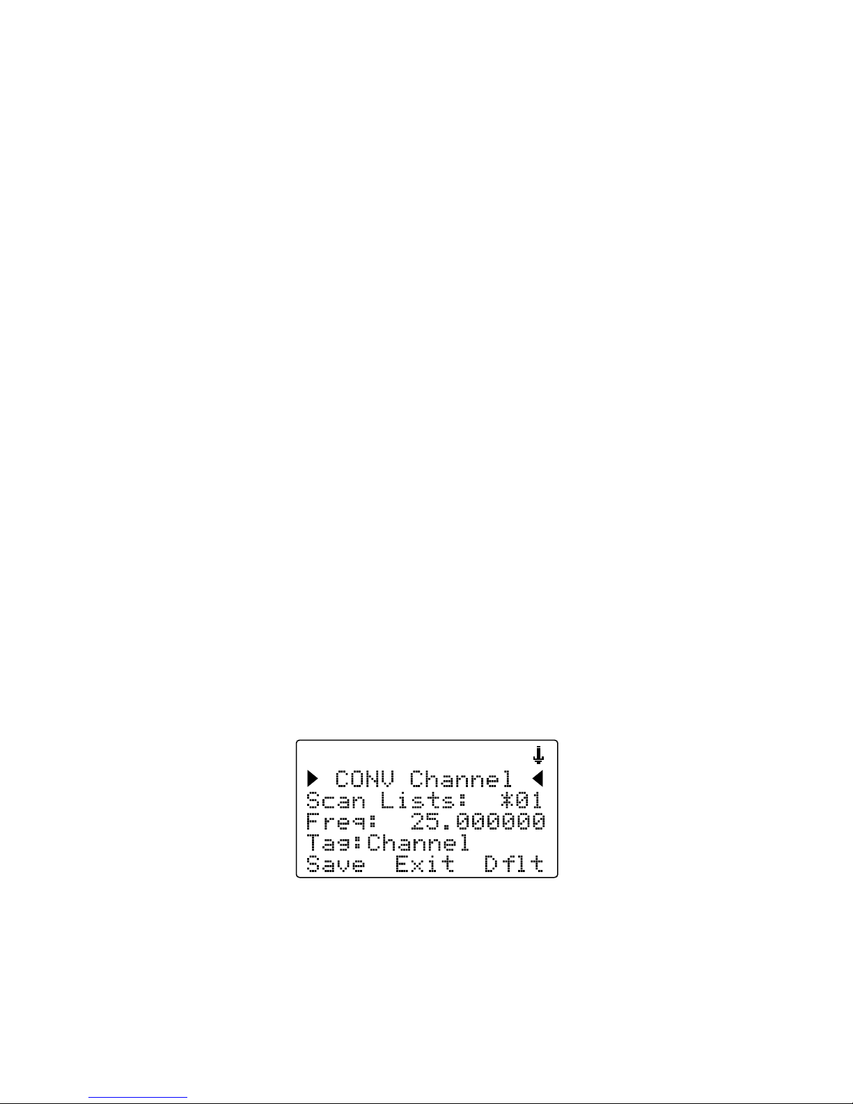
Your scanner's display should read as follows:
Now, take a moment and study the display. You will notice that the 6 icon
is active. Its purpose is to indicate that you are at the very top position of
the menu for a conventional channel object, and there are more parameters
that can be accessed if you scroll down. We also see three new softkeys:

29
Save Exit Dflt
The
Save
softkey will save your new CONV object to the file system when
pressed (but don't press it yet!). The
Exit
softkey aborts the creation of
the new CONV object, and the
Dflt
softkey restores the selected CONV
menu parameter to its default setting.
If you press the 6 key on the bottom of the 5-way pushbutton pad, you can
scroll down and see all of the parameters that can be specified for a CONV
object. Go ahead and take a peek - then scroll back to the very top of the
display so you can begin entering information for your first CONV object.
HINT: Pressing FUNC 5 or FUNC 6 will jump to the top or bottom of a
menu, respectively.
Note that as you scroll both the upward and downward scroll indicators
will illuminate to indicate that there are parameters above and below the
current cursor position, until you get to the very end of the menu, where
only the upward scroll indicator will be on to indicate that there are no more
parameters below the current cursor position. Also note that a few lines of
context sensitive help are available for each menu item. To see the help text
for a menu item, press FUNC, then press SEL on the 5-way pushbutton
pad. To exit help, press SEL again.
As you scroll the object menu, you will see a line that states:
66
EXPERT BELOW
66
This line is found in the object menus and the Global configuration menus.
Its purpose is to delineate between the basic settings that are important to
each object and the operation of the radio, and the expert settings that may
be of interest to advanced users, but, if left alone, will not adversely impact
the operation of the radio. For more information about the Basic and Expert
settings, please refer to the Detailed Menu Reference at the end of this
Owner's Manual.
Use the
56
keys to scroll the screen until the flashing cursor appears next
to the
Freq:
label. Key in a known local frequency and press the ENT
key, or press the
DONE
softkey - either one will do the same thing. There!
You just entered the frequency for your first CONV object.

30
By default, your new CONV object will be tagged “Channel”. If you'd like to
change this, just scroll the screen down one click until the flashing cursor
highlights the
Tag:
field, then press SEL to edit the tag. You can move the
cursor around using the
34
keys on the 5-way pushbutton pad, use the
CLR key to clear the old text, or press FUNC CLR to erase the entire field.
To enter text, find the letter you want to enter on the front panel of the radio,
press the numeric key beneath it, then press 1, 2, 3, or 4 depending on
the position of the letter in the group for that number. For example, to enter
FIRE
, press:
3 3 F
4 3 I
7 3 R
3 2 E
Press the ENT key or
DONE
softkey to store the new tag information for
your CONV object.
Now you are ready to store your first CONV object. There are other
parameters that you can change, and we invite you to scroll through the
CONV menu to see the other settings that are available. You can experiment
with the different settings. If you make a change that you aren't certain
about, press the
Dflt
softkey to restore the setting to its original values.
When you're ready, simply press the
Save
softkey to save your new
conventional object. Once the object is saved, you can continue to enter
other new objects, or press MAN to listen to the CONV object you just
entered, or SCAN to start scanning!
NOTE: Your scanner uses Scan Lists as a way to group objects together
according to your preferences for scanning. By default, all new objects are
mapped to Scan List 01. There are a total of twenty regular Scan Lists in
your radio, a special Favorites Scan List, and a Scan List to hold Skywarn
objects. Scan List membership for an object is assigned in the individual
object menus. For now, just let your new objects go to the default Scan List
01. Later in this section we will show you how you can group your objects
into Scan Lists.
NOTE: When entering data into a numerical field, you can start typing
as soon as you have scrolled to the desired field, which will replace the
contents of the field with your new entry. Alternatively, you can press the 4
key, which will preserve the original contents of the field so you can make
small changes without retyping all of the data.
 Loading...