


Table of Contents
..........................................................................................................Introduction! 5
...........................................................................................................Features! 6
..................................................................................................TGRP! 13
...................................................................................................TSYS! 13
..................................................................................................CONV! 14
....................................................................................................LMIT! 14
..................................................................................................SRVC! 14
..................................................................................................SWPR! 14
...................................................................................................Softkeys! 21
...................................................................................................Getting Started! 23
..........................................Overview of the Object Oriented User Interface! 8
...............................................................................................Background! 8
......................................................What is Object Oriented Scanning?! 11
........................................................................................About this manual! 13
.......................................Object abbreviations used in this document! 13
......................................................................The FCC Wants You To Know! 14
..........................................................................................Scanning Legally! 15
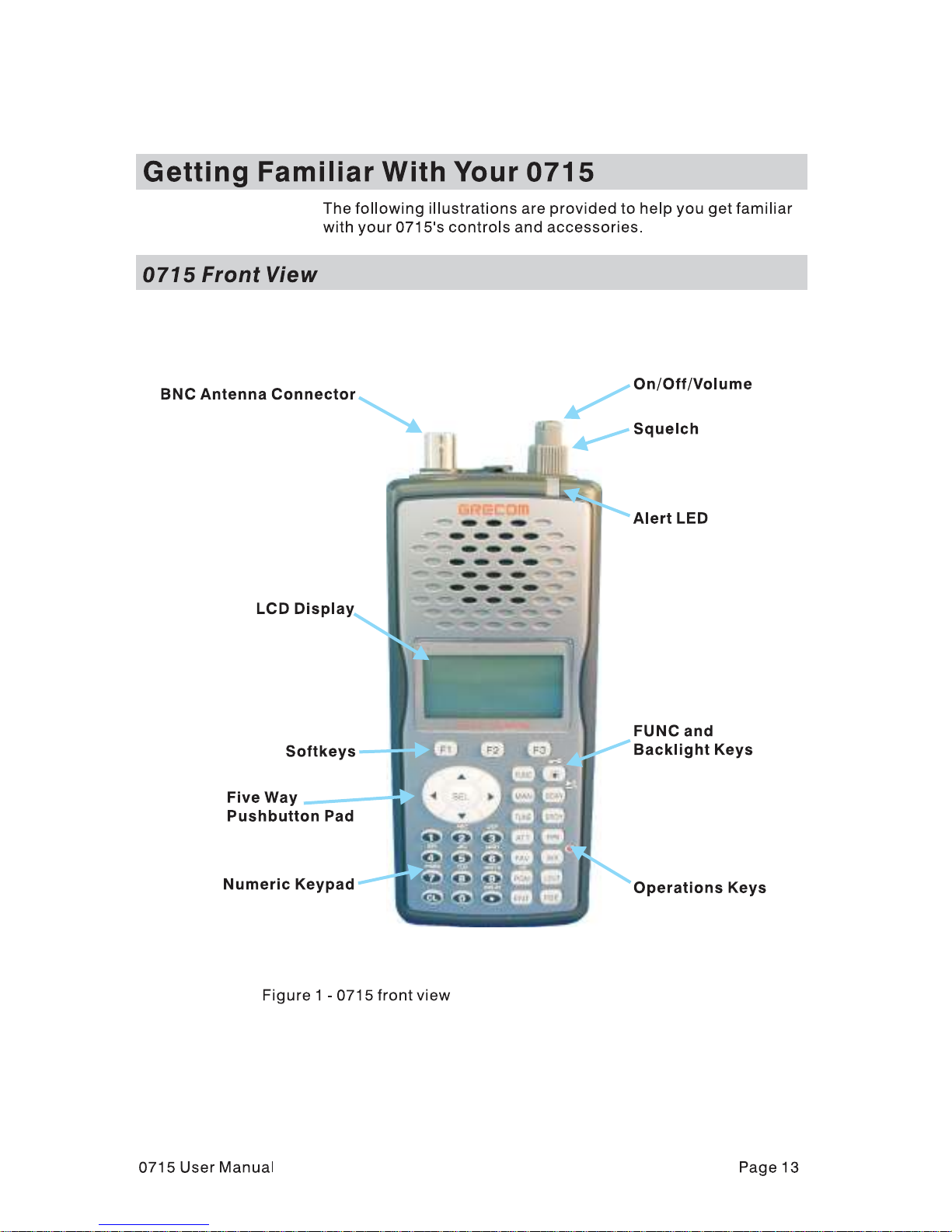
.......................................................................Getting Familiar With Your 0715! 17
............................................................................................0715 Front View! 17
.............................................................................................0715 Rear View! 18
.........................................................................................0715 Accessories! 19
...............................................................Understanding the Display Icons! 20
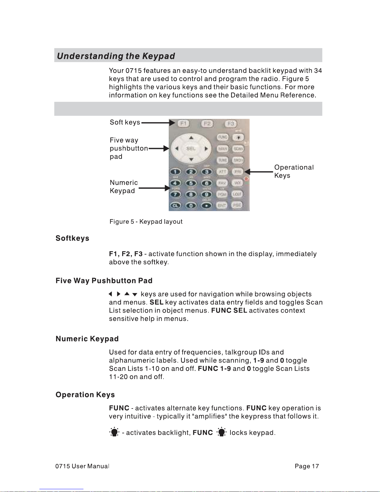
..........................................................................Understanding the Keypad! 21
......................................................................Five Way Pushbutton Pad! 21
......................................................................................Numeric Keypad! 21
.......................................................................................Operation Keys! 21
.........................................................................................First Time Startup! 23
.....................................................................................Unpack the radio! 23
..................................................................................Insert the batteries! 23
..................................................................................Attach the antenna! 24
.....................................................................................Turn the radio on! 24
.................................................................Creating Your First New Objects! 24
..................................................Conventional Channel Object (CONV)! 25
.................................Essential Conventional Channel parameters! 25
.......................................................................Talkgroup Object (TGRP)! 28
......................................Essential Trunking Talkgroup parameters! 28
...............Setting up and using a Trunking System (TSYS) object! 28
..................................................Using DUPE to speed up object entry! 32
.....................................................................Basic Scanning Operation! 32
............................................................................Advanced Startup Topics! 35
.......................................................................About Object Numbering! 35
...............................................................................Search Object Types! 35

...............................................................Limit Search Object (LMIT)! 36
............................................Essential Limit Search parameters! 36
..................................................Spectrum Sweeper Object (SWPR)! 37
..................................Essential Spectrum Sweeper parameters! 38
.........................................................Service Search Object (SRVC)! 39
........................................Essential Service Search parameters! 39
............................................................Grouping Objects in Scan Lists! 41
...................................................................................Geographically! 42
...........................................................................By trunking system! 42
....................................................................................By object type! 42
....................................................................................By application! 43
........................................................Mapping Objects to Scan Lists! 43
..................................................Enabling and disabling Scan Lists! 44
..............................................................................Other Startup Topics! 45
..........................................................Finding Stored Objects Easily! 45
............................................Searching For Objects Using FIND! 45
..............................................................Filtering By Object Type! 45
..................................................................................Object Lockout! 46
......................................................................Temporary Lockout! 46
.....................................................................Permanent Lockout ! 47
............................................................................Search Lockout! 47
.......................................................................Talkgroup Lockout! 48
................................................................................Deleting Objects! 49
......................................................................................Priority Scan! 49
...............................................Turning Object Priority On or Off! 49
........................................Turning Priority Scan Mode On or Off! 50
......................................................................CONV Priority Scan! 50
......................................................................TGRP Priority Scan! 50
...............................................Audible Alarms and the ALERT LED! 51
...................................Audible Alarm and ALERT LED Settings! 51
................................ALERT LED with Audible Alarm Examples! 51
..................................................................Dedicated search modes! 52
.................Using Dedicated Spectrum Sweeper (SWPR) Mode! 52
......................................................Using dedicated TUNE mode! 54
...................Using dedicated Limit and Service search modes! 55
.......................................................................LMIT Search Mode! 55
......................................................Using dedicated SRVC mode! 56
.......................................................................Using Weather Modes! 58
....................................................................Weather Radio Mode! 58
.................................................................Weather Priority Mode! 59
...................................................................SAME Standby Mode! 59
.................................................................SAME Entry Examples! 61
...............................Entering SAME Location and Event Codes! 62
.................................................Activating SAME Standby Mode! 65
.................................................................Using V-Scanner Storage! 65
.............................Saving Main Memory To A V-Scanner Folder! 66

..............Loading A Stored V-Scanner Folder To Main Memory! 66
.........................................................Erasing V-Scanner Folders! 67
..............................................Standard Text Entry Method and QuickText! 67
.................................Entering and Editing Alphanumeric Information! 67
......................................................................................Using QuickText ! 69
..........................................................................Customizing QuickText! 70
..................................................................................Detailed Menu Reference! 70
................................................................................GLOB Menu Reference! 72
................................................................................CONV Menu Reference! 75
.................................................................................TGRP Menu Reference! 77
.................................................................................TSYS Menu Reference! 79
..................................................................................LMIT Menu Reference! 81
.................................................................................SRVC Menu Reference! 83
................................................................................SWPR Menu Reference! 86
...................................................................................................................Index! 89
.....................................Appendix A - Remote Control Protocol Version 0.01! 92
................................................................................................Get Status! 92
....................................................................................................Get LCD! 93
..................................................................................................Send Key! 93
...............................Appendix B - Frequency, Step and Mode Specifications! 95
........................................Appendix C - General Specifications (Preliminary)! 96

Introduction
Welcome to an exciting new world of radio scanning!
Recognizing that contemporary scanning receivers are too hard
to program and use, GRE!s engineers conducted extensive
research to determine the functional requirements for an entirely
new scanning receiver user interface. We call this new user
interface the Object Oriented User Interface (OOUI), and it is
based on the premise that, to a hobbyist, a scanner is easiest to
use if all of the things that can be scanned are handled using
common conventions for interaction between the user and the
radio, at least to the extent that this is possible given that the
“things” that can be scanned are different from one another in
either subtle or major ways.
In this new user interface design, we call “things” that can be
scanned Scannable Objects. Simply put, a Scannable Object is
defined as something that can be scanned or monitored.
Scannable Objects include the following:
Conventional, non-trunked radio channels
•
Trunked talkgroups used on a trunked radio system
•
Service searches to search for a specific radio service
•
Search ranges with upper and lower limits
•
Spectrum Sweeper setups with band segments that can be
•
enabled or disabled by the user
One of the goals of the Object Oriented User Interface is to make
the scanner as easy to use as possible. The OOUI does this by
treating all Scannable Objects the same in terms of how they are
created, edited, manipulated and grouped. Once you have
learned how to create and store a conventional channel, you
know most of what you need to know to create a trunking
talkgroup, and so on.
While we have designed this radio to be the easiest scanning
receiver in its class to program and use, we encourage you to
read this manual in its entirety so that you will fully understand all
of the radio!s capabilities. However, if you consider yourself to be
an experienced scanning hobbyist and are feeling adventurous,
we invite you to dive right in and get started programming your
favorite “objects” into the radio.
0715 User Manual" Page 1

Features
Upgradeable CPU and DSP Firmware - keep your radio current
with enhancements as they become available with free upgrades
from www.greamerica.com!
Intuitive "Object Oriented" User Interface Design is designed
for ease of use, yet powerful enough to satisfy the most
sophisticated experts. Common data entry, browsing and control
methods are used for non-trunked conventional channels,
trunking talkgroups, search configurations and Spectrum
Sweeper setups. The radio grows with you – you can start out
with a small, easy to manage configuration, then expand it
whenever you need to.
Menu Driven Programming With Context Sensitive Help Each menu item provides a few lines of help text that provide
assistance with programming and using the scanner.
Powerful and flexible Scan List functionality allows you to
arrange, group and scan objects according to your preference.
Flexible Free-Form Memory Organization - memory is
assigned as objects are created using a sophisticated internal file
management system. You are not constrained to traditional bank/
channel scanner memory layouts. No memory is wasted as a
result of bank/channel programming constraints. The scanner
has sufficient main memory capacity to store over 1,800
conventional channels, trunking talkgroups, search
configurations and Spectrum Sweeper objects in any
combination, providing ample capacity for more sophisticated
hobbyists and professionals while keeping the database size
manageable for beginners.
GRE's Exclusive V-Scanner Technology - Allows you to save
complete radio configurations within the radio, for recall into main
memory as needed in the field. This is similar to having a laptop
computer and programming software available anytime. You can
use V-Scanners to store configurations for different geographical
areas or usage styles. Twenty one V-Scanner Folders are
provided, each capable of storing over 1,800 objects. Total
memory capacity of main memory combined with V-Scanners is
over 37,800 objects!
SKYWARN Storm Spotter Functionality - Instant, one button
access to frequencies used by storm spotter networks. You can
monitor storm conditions as they occur, and become aware of
0715 User Manual" Page 2

dangerous conditions before the media or emergency
management officials are able to announce them to the general
public.
SAME and All Hazards Weather Alerting - Your scanner can
operate in dedicated SAME weather alerting mode, and alert you
to severe weather and other hazards in the specific area(s) that
you select, or, your scanner can check your local NOAA weather
frequency periodically, even while scanning and alert you when
an All Hazards alert occurs.
Multi-System Trunking - Scans most common trunked radio
system signaling formats, including Motorola, EDACS, LTR and
P25 trunked radio networks. Talkgroup and individual call
monitoring is supported.
GRE's Exclusive Automatic Adaptive Digital Tracking - When
monitoring P25 digital systems, instantly adapts the digital
decoder to the digital modulation format of the transmitted signal,
then analyzes the signal over 50 times each second and adapts
to any subtle changes caused by multipath or fading. No
cumbersome manual adjustments are required.
GRE's Exclusive Digital AGC - instantly compensates for low
user audio levels that are very common on digital systems. The
radio is easier to listen to, and provides you with a more
enjoyable scanning experience.
The Best Subaudible Squelch Decoder in the Scanning
Industry - CTCSS and DCS subaudible squelch coding is
processed by the same powerful DSP chip that is used for P25
digital decoding. Provides fast and reliable decoding of
subaudible squelch signaling with squelch tail elimination.
Powerful Spectrum Sweeper - Quickly sweeps the scanner!s
frequency ranges for transmissions from nearby transmitters.
P25 NAC Functionality - Much like CTCSS and DCS with
analog signals, P25 Network Access Code (NAC) is used to
provide selective squelch operation on conventional digital
channels. Your 0715 will detect the NAC that is being used on a
P25 conventional digital channel, and allow you to program NAC
codes to block transmissions that do not have a matching NAC,
including analog traffic on the same frequency!
Exclusive ALERT LED - Programmable tri-color LED can be
configured to illuminate or flash when certain objects are active.
0715 User Manual" Page 3

Eight user-defined colors and brightness levels can be specified
from thousands of possible combinations. Provides visual alerts
when certain channels are active, e.g., blue can be used to
signal activity on your primary police channel, red for fire, etc.
Audible alarms - Programmable audible alarms can be
configured to sound when certain objects are active. Can be
used in conjunction with, or separately from, the ALERT LED
described above.
High Speed PC Interface - uses GRE!s 30-3290 USB cable in
full duplex mode at 6 times the speed of previous scanner
models for PC transfer and 8 times the speed of previous models
for radio to radio cloning.
Real-time Signal Strength Indicator – shows relative strength
of received signals.
Sleek, compact case design with large speaker is designed
for one-handed operation and ease of use.
Overview of the Object Oriented User Interface
Background
Scanner hobbyists who have been involved in the hobby long
enough probably remember the days before microprocessor
technology reached the point where it feasible for use in
everyday consumer devices. Back then, scanners were relatively
limited in what they were able to do. A typical scanner was able
to scan between 2 and 10 frequencies. The frequencies were
selected using plug-in crystal elements, and a custom crystal had
to be purchased for each frequency that a user wished to scan.
Scanning activity was typically shown using a row of
incandescent or LED indicators. These indicators would show
scanning operation in progress as the scanner moved from one
channel to the next, looking for activity, and would indicate the
active channel when activity was found. Pushbuttons or switches
were used to skip or lock out undesired channels. The scanning
row of LED or incandescent indicators seemed to personify the
hobby at the time, and it was quite an experience to see the light
show from multiple radios in a well-equipped scanner shack
Early microprocessor controlled scanners eliminated the need for
crystals and increased the number of channels that could be
scanned. Without keypads and numeric or alphanumeric displays
these early microprocessor controlled radios still relied on the
0715 User Manual" Page 4

traditional row of lights to show scanning activity. A row of
switches was used to enter binary code to store individual
frequencies. In some later models a punch card or metal comb
was used to load the binary code.
The true predecessors of today!s modern scanning receivers are
those first radios to use a numeric keypad to store frequency
information and control the radio, and numeric LCDs to show the
programmed information and display the status of the radio. The
row of lights was replaced with a row of zeroes or other display
elements in the LCD to show scanning activity.
As it became possible to increase the memory capacity of these
microprocessor controlled scanners, designers started looking
for ways to organize this expanded memory to make operation
easier for users. This lead to the typical bank/channel memory
organization that is still used in many scanning receivers today.
This design works well when scanning conventional, non-trunked
frequencies.
Trunking presented new challenges for designers. Early designs
operated in trunking or conventional mode, but not both at the
same time. Because programming for trunked systems includes
many parameters not normally used in conventional radio
scanning, it was necessary to design a completely separate user
interface for entering trunking parameters and scanning trunked
systems. Soon after the first early models were released, new
“multi-scanning” receivers appeared that allowed users to scan
different combinations of trunked systems or conventional
channels simultaneously.
Trunking scanners soon earned a reputation for being complex
and difficult to program. Even experienced expert users were
frustrated when confronted with the challenges of programming
and operating a trunked scanning receiver. Part of the problem
with trunking scanners was the way that trunking functionality
was added to the radio. Until recently, trunking functionality was
forced into the traditional bank/channel scanner design. This
created confusion and frustration for users, who had to learn two
different methods for programming and controlling their scanners
– one for conventional, non-trunked channels, and another for
trunked systems and talkgroups.
GRE!s engineers have studied the challenges of programming
and operating today!s current crop of trunked scanning receivers.
We have also carefully studied how scanning hobbyists like to
use their radios, and the role the Internet plays in the scanning
0715 User Manual" Page 5

hobby. We have studied the scanning hobby itself, which has
changed dramatically over the years as radio systems, scanning
receivers and scanner hobbyists have all become more
sophisticated. Sophistication is a generally good thing, but in this
case it can have the effect of locking out newcomers to the
hobby.
Our engineers decided that an entirely new method of
programming and controlling scanning receivers was needed –
essentially, a new user interface. Several design objectives were
defined. These included the following:
There should be a strong focus on ease-of-use.
•
should do as much work as possible for the user. A brand
new hobbyist should be able to begin using the radio quickly
with minimal frustration. There should also be enough
advanced features and functionalities to satisfy the most
sophisticated expert users.
The user interface should be intuitive.
•
radio should be standardized to the extent possible. For
example, the same basic methods should be used whether
adding a new conventional channel or adding a trunked
talkgroup.
The scanner should include efficient memory usage.
•
channel designs result in much wasted memory. Memory
should be allocated as it is needed for new objects.
Our engineers realize that our scanners are used by a wide
variety of users with varying levels of experience and expertise.
These include amateur radio operators, scanner hobbyists, fire
buffs, railfans, public safety professionals, volunteer firefighters,
news and media organizations, and most importantly, everyday
people who just want to know what is going on around them.
Interactions with the
The radio
Bank/
All of these users have a few things in common about the way
they use scanning receivers. First, they all follow the same basic
process when configuring and programming the radio for use.
Second, all have one or more collections of frequencies,
talkgroups, or other things they listen to.
As our engineers studied the scanning hobby and those who use
scanners, they began to realize that the scanning hobby had
much in common with hobbies that involve collections, like stamp
collecting, coin collecting, and so on.
0715 User Manual" Page 6

Hobbies of collection all have some things in common:
Typically, a collector starts off small, and adds to the
•
collection
A collector groups items in the collection according to their
•
type
A collector looks for new things to add to the collection
•
A collector removes items from the collection that they no
•
longer desire
A collector enjoys the collection
•
Specifically, with regard to scanning:
At first, the typical scannist starts off small, and expands. This
•
is especially true with beginners and newcomers to the
hobby.
The scannist groups channels and talkgroups according to
•
area or type of use
The scannist searches or tunes to find new things to scan
•
A scannist removes channels and talkgroups they no longer
•
need
A scannist enjoys the collection of channels and talkgroups
•
they have programmed into the scanner
Our engineers determined that a new scanner design would be
most useful if it could be used as a tool by the scanning hobbyist
to build and enjoy the collection of channels and trunked
talkgroups they have programmed into the scanner.
Much of what you see in the design of your new GRE scanner
with Object Oriented User Interface is intended to meet the
objectives we describe above, and serve as a tool to help you
manage and enjoy your collection of “Scannable Objects”.
What is Object Oriented Scanning?
To put it simply, Object Oriented Scanning describes a new user
interface design for scanning receivers (the Object Oriented User
Interface, or OOUI). In Object Oriented Scanning, we introduce
0715 User Manual" Page 7

the concept of the Scannable Object. A Scannable Object is
defined as “something that can be scanned”.
The Scannable Object concept is very important in the OOUI
design. Recall that one of the more frustrating things about
current trunking scanners is that entirely different methods of
programming and interacting with the radio are used depending
on whether the user is working with trunking talkgroups or
conventional channels. A method that works with one does not
work with the other. The user must learn two entirely different
“languages” for “talking to” the radio – one for trunking and one
for conventional, non-trunked frequencies.
What if it was possible to use the same basic “language”
regardless of whether a user is working with trunked talkgroups
or conventional channels, such that once a user has learned how
to enter a conventional channel into memory, they already know
most of what they need to know to enter a trunked talkgroup? Or,
a search range, or other “Scannable Objects”? This is how the
OOUI works – the two primary Scannable Objects, talkgroups on
trunked radio systems and conventional non-trunked frequencies
use the same user interface elements.
Additionally, we include limit and service search configurations
and Spectrum Sweeper configurations as Scannable Objects.
This means that it is possible to create, edit, group, scan and
delete service and limit searches, and SWPR configurations
using the same methods that are used when working with
trunked talkgroups and conventional channels.
Object Oriented Scanning also lends itself quite well to the
“collector hobbyist model” we describe above. Object Oriented
Scanning makes it very easy for newcomers to the hobby or the
radio to start off with a small collection Scannable Objects and
expand their collection as needed later. Object Oriented
Scanning makes it easy to group Scannable Objects in Scan
Lists, a powerful and flexible grouping system. Object Oriented
Scanning makes it easy to search for new frequencies or
talkgroups to monitor, and add them to existing or new Scan List
groups. Object Oriented Scanning makes it very easy to delete
or deactivate objects and Scan Lists that you do not want to
listen to, including a powerful temporary lockout mode that allows
you to zero in on activity associated with a specific incident, then
restore your desired configuration when the incident is over.
Finally, Object Oriented Scanning makes it exceedingly easy for
0715 User Manual" Page 8

the scannist to enjoy the collection of channels and talkgroups
they have programmed into the scanner.
About this manual
Object abbreviations used in this document
We described how your new GRE scanner utilizes an Object
Oriented User Interface in the Introduction and Overview
sections of this manual. You learned that the key components of
this new user interface are the Scannable Objects, which are, of
course, “things that can be scanned”. As you begin to use your
new scanner, you will notice that the object names are
abbreviated so that they can easily fit into the 16 character LCD.
(Imagine what the radio!s display would look like if “Trunking
Talkgroup Object” was spelled out in its entirety every time it was
necessary to show it in the display.)
You should take a moment and become familiar with these
abbreviations now. For consistency, the same abbreviations for
the different object types are used in the radio and here in the
manual.
TGRP
TSYS
TGRP is used to represent a Trunking Talkgroup Object.
Trunking Talkgroups are “virtual” channels that exist on a trunked
radio system. A trunked radio system is a radio system where a
small group of radio channels are automatically shared between
a larger number of users and user groups. This of sharing of
channels is managed automatically by a special computer, called
a controller, or by other specialized hardware. For now, all you
need to know is this; if you want to monitor a talkgroup on a
trunked radio system, you must store that talkgroup!s parameters
in a TGRP object.
TSYS is used to represent a Trunking System Object. A TSYS is
a special object type that is used when creating TGRP objects. A
trunking talkgroup must be associated with a specific trunked
radio system in order for it to operate. There are parameters that
are associated with trunking systems, such as the type of
trunked radio system technology is used, the frequencies that the
system uses to broadcast control data, etc. Instead of entering
these parameters over and over again every time you create a
new TGRP on the same trunked radio system, you create a
0715 User Manual" Page 9

CONV
LMIT
TSYS object with all of the system parameters, then specify that
TSYS object for each TGRP you create on the same trunked
radio system. A TSYS cannot be scanned by itself and is not
considered a Scannable Object. It is a “configuration object” that
can be used over and over again when adding talkgroups for a
specified trunked radio system.
CONV is used to represent a Conventional Channel Object. A
Conventional Channel Object is a regular, non-trunked frequency
used for radio communications. CONV objects are used to store
the parameters for any radio channel that is not a part of a
trunked system. For example, if you want to monitor specific VHF
marine channels, they should be programmed as CONV objects.
If you want to monitor your favorite amateur radio repeater, it
should be stored as a CONV object. If your police or fire
department uses a channel, or channels that are not trunked, but
part of a “plain old radio system”, they should be stored as
CONV objects.
LMIT is used to represent a Search Range, or Limit Search
Object. LMIT objects contain the parameters necessary for the
radio to search a range of individual frequencies between a lower
and upper limit frequency.
SRVC
SRVC is used to represent a Service Search Object. SRVC
objects are further divided into Public Safety, Aircraft, Amateur,
CB, Marine, and FRS/GM/MURS/DOT. SRVC objects are similar
to LMIT objects, but are preprogrammed to search all
frequencies associated with the selected service. For example,
selecting the Amateur SRVC search will search selected amateur
radio frequency ranges frequencies in the VHF and UHF portions
of the radio spectrum.
SWPR
SWPR is used to represent a Spectrum Sweeper Object. SWPR
objects contain the parameters necessary for the radio to rapidly
sweep a range of radio spectrum for strong signals from nearby
transmitters.
The FCC Wants You To Know
This equipment has been tested and found to comply with the
limits for a scanning receiver, pursuant to Part 15 of the FCC
0715 User Manual" Page 10

Rules. These limits are designed to provide reasonable
protection against harmful interference in a residential
installation. This equipment generates, uses and can radiate
radio frequency energy and, if not installed and used in
accordance with the instructions, may cause harmful interference
to radio communications.
However, there is no guarantee that interference will not occur in
a particular installation. If this equipment does cause harmful
interference to radio or television reception, which can be
determined by turning the equipment off and on, the user is
encouraged to try to correct the interference by one or more of
the following measures:
• Reorient or relocate the receiving antenna.
• Increase the separation between the equipment and receiver.
• Connect the equipment into an outlet on a circuit different from
that to which the receiver is connected.
This device complies with Part 15 of the FCC Rules. Operation is
subject to the following two conditions:
1." This device may not cause harmful interference.
2." This device must accept any interference received, including
interference that may cause undesired operation.
Scanning Legally
Your scanner covers frequencies used by many different groups
including police and fire departments, ambulance services,
government agencies, private companies, amateur radio
services, military operations, pager services, and wireline
(telephone and telegraph) service providers. It is legal to listen to
almost every transmission your scanner can receive. However,
there are some transmissions you should never intentionally
listen to. These include:
Telephone conversations (cellular, cordless, or other means
•
of private telephone signal transmission)
Paging transmissions
•
Any intentionally decoded scrambled or encrypted
•
transmissions
0715 User Manual" Page 11

According to the Electronic Communications Privacy Act (ECPA),
you are subject to fines and possible imprisonment for
intentionally listening to, using, or divulging the contents of such
a transmission unless you have the consent of a party to the
communication (unless such activity is otherwise illegal).
This scanner has been designed to prevent reception of illegal
transmissions. This is done to comply with the legal requirement
that scanners be manufactured so as to not be easily modifiable
to pick up those transmissions. Do not open your scanner's case
to make any modifications that could allow it to pick up
transmissions that are illegal to monitor. Doing so could subject
you to legal penalties.
We encourage responsible, legal scanner use.
In some areas, mobile use of this scanner is unlawful or requires
a permit. Check the laws in your area. It is also illegal in many
areas to interfere with the duties of public safety officials by
traveling to the scene of an incident without authorization.
0715 User Manual" Page 12

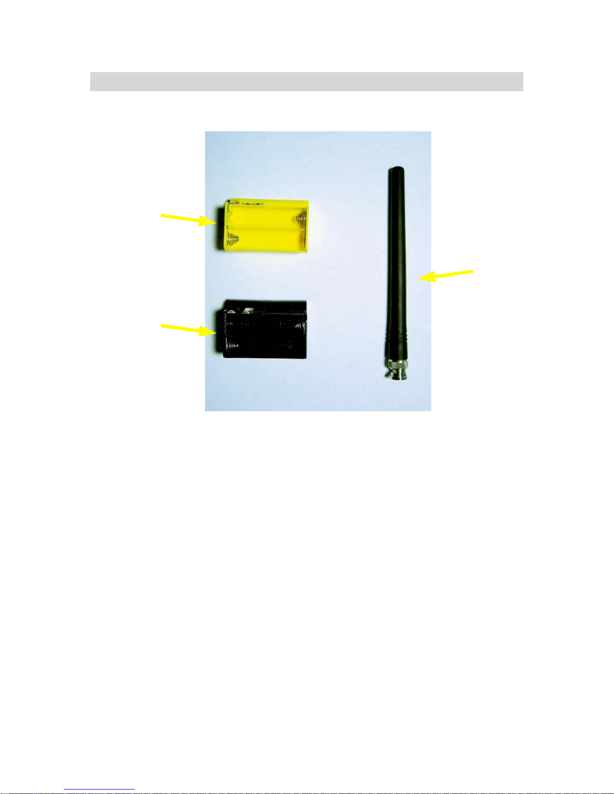
0715 Accessories
Yellow battery
holder for
rechargeable
batteries
Antenna
Black battery
holder for
standard batteries
Figure 3 - 0715 Accessories
0715 User Manual" Page 15
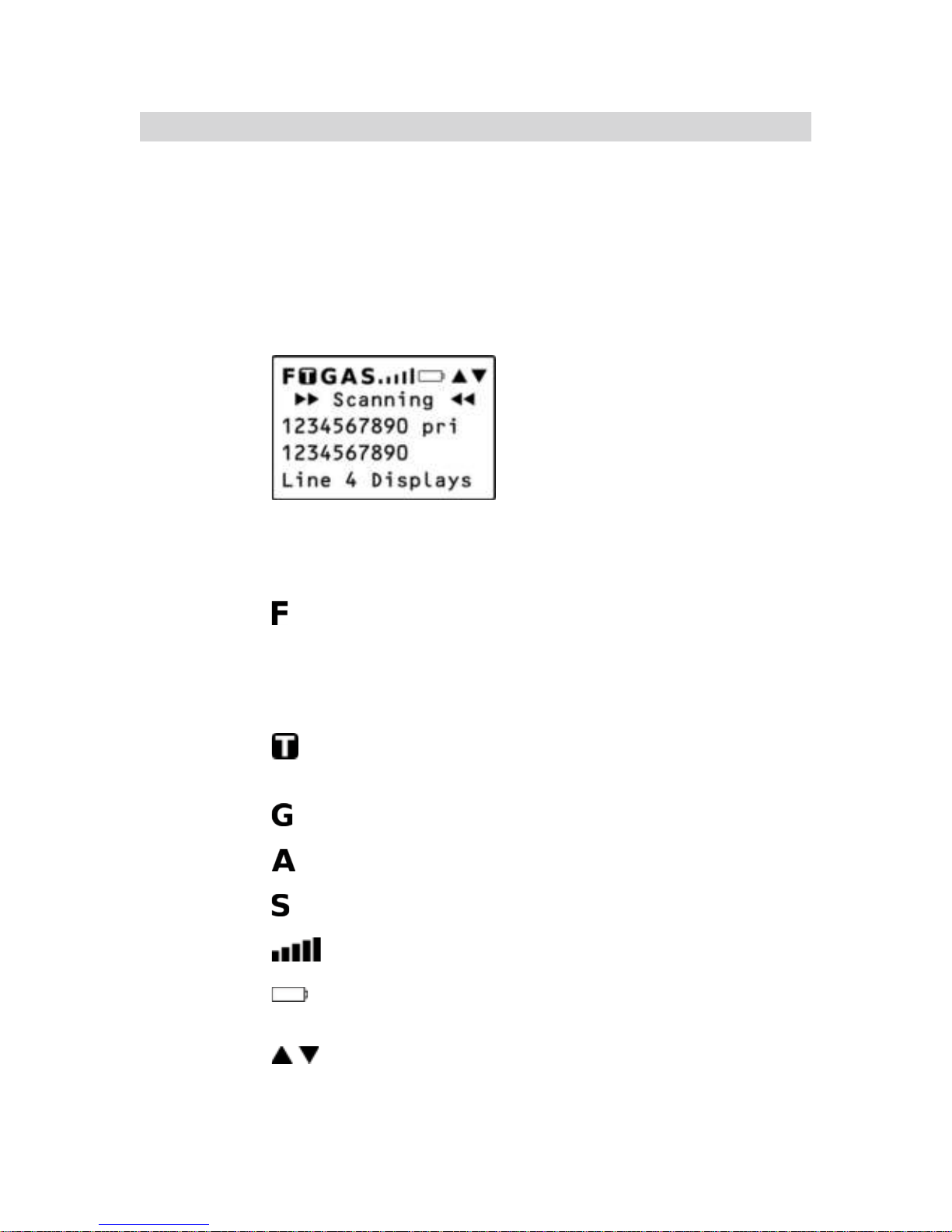
Understanding the Display Icons
Your 0715 features a high contrast, backlit Liquid Crystal Display
(LCD) to provide important information about the status of the
radio while you are programming and using it. The LCD includes
a row of icons at the top that provides information about the
status of the scanner while it is operating. Beneath this row of
icons, there are 4 rows of 16 characters each that provide
alphanumeric information for frequencies, object names, Scan
List status and menu information. Figure 4 provides an example
of the display that is shown while the radio is scanning.
Figure 4 - Scanning Display
The top row of icons are defined as follows:
The Function Key (FUNC) has been pressed. FUNC acts
as a “shift” key and typically enhances in some way the
action of the button that follows it. When using FUNC,
press the FUNC key first and release it, then press the
next key.
The scanner is currently receiving trunking control channel
data.
The attenuator is set for Global mode.
The attenuator is currently active.
The radio!s squelch circuit is open.
Signal meter indicating strength of the received signal.
Battery status indicator. Comes on solid when battery is
weak, and flashes when battery failure is imminent.
Menu position and search direction indicators.
0715 User Manual Page 16

MAN - Places scanner in Manual Mode for monitoring single
objects.
SCAN - Places scanner in Scan Mode for scanning enabled
objects, FUNC SCAN launches Spectrum Sweeper.
TUNE - Allows direct tuning of any valid frequency, FUNC TUNE
loads the current or most recently scanned frequency into TUNE
SRCH - Dedicated Search mode for service and frequency
searches
ATT - Toggles Attenuator on and off, FUNC ATT toggles Global
Attenuator mode
PRI - Toggles the Priority setting for selected or active object,
FUNC PRI toggles Priority Mode on or off for the scanner
FAV - Activates Favorites Scan Mode, FUNC FAV adds the
current object to the Favorites scan list
WX - Activates Weather scan, FUNC WX activates Skywarn mode
PGM - Places scanner in Program Mode for editing radio-wide
options, adding new objects or editing existing objects, FUNC
PGM accesses V-Scanner mode
L/OUT - Toggles Temporary Lockout on active or selected object,
FUNC L/OUT applies permanent lockout (can be changed in the
GLOB menu)
ENT - Enter key
PSE - Pauses scan or search operation on active object
0715 User Manual" Page 18

Getting Started
First Time Startup
We believe that your new 0715 is so easy to use that scannists
with at least some experience in the hobby should be able to get
up and running in a matter of just a few minutes. If you already
know the difference between a conventional channel and a
talkgroup, or a search range and a Spectrum Sweeper, we invite
you to dive right in and set the radio up to begin scanning your
first objects. If you get stuck, you can refer to this Getting Started
section, or see the relevant sections in the Detailed Menu
Reference. Otherwise, please read on and allow us to help you
get acquainted to your new scanner!
Unpack the radio
Unpack your radio carefully. Save all documentation and packing
materials in case it is necessary to return your scanner for repair.
Insert the batteries
Remove the door covering the battery compartment by pressing
gently where the door is marked OPEN and sliding the door
downwards until it stops, approximately 1/4”. Lift the door away
from the radio. Remove the supplied battery holder. Insert four
AA batteries into the holder, taking care to ensure that the
batteries are inserted according to the diagram shown inside of
the holder assembly. Insert the holder into the battery
compartment, then replace the battery compartment door by
placing it back over the batteries and sliding it upward gently until
it locks in place.
NOTE: Two battery holders are included with your 0715. The black battery
holder should be used with non-rechargeable alkaline batteries. The
yellow battery holder should be used with rechargeable NiMH or
NiCAD batteries. The radio will charge the batteries when the yellow
holder is used in conjunction with an approved AC adapter.
WARNING: Never place non-rechargeable batteries in the yellow holder.
Intentionally or accidentally recharging non-rechargeable
batteries will cause them to leak or explode.
0715 User Manual" Page 19
Attach the antenna
Remove the antenna from its protective plastic wrapper. Align the
slots on the antenna!s BNC male connector with the posts on the
radio!s BNC female connector and slide the antenna in place,
then rotate the antenna!s BNC connector 1/4 turn clockwise until
it snaps in place.
Turn the radio on
Rotate the top knob of the VOLUME/SQUELCH control
clockwise to turn the radio on. Set both the VOLUME and
SQUELCH knobs at their mid-point (12 o!clock) position.
NOTE: While 12 o!clock is a good squelch setting to start with, it may cause
your radio to miss some calls with weak signals. You will probably
want to optimize the squelch setting to set it close to threshold. To
optimize the squelch setting to be close to the best threshold, press
TUNE, then rotate the squelch control counterclockwise until a
rushing sound is heard from the speaker. Rotate the squelch control
clockwise just past the point where the rushing sound stops. The
squelch is now set to the optimum point. Please note the position of
the squelch control for future reference. Once the squelch setting is
complete, you may press PGM to exit TUNE mode.
Creating Your First New Objects
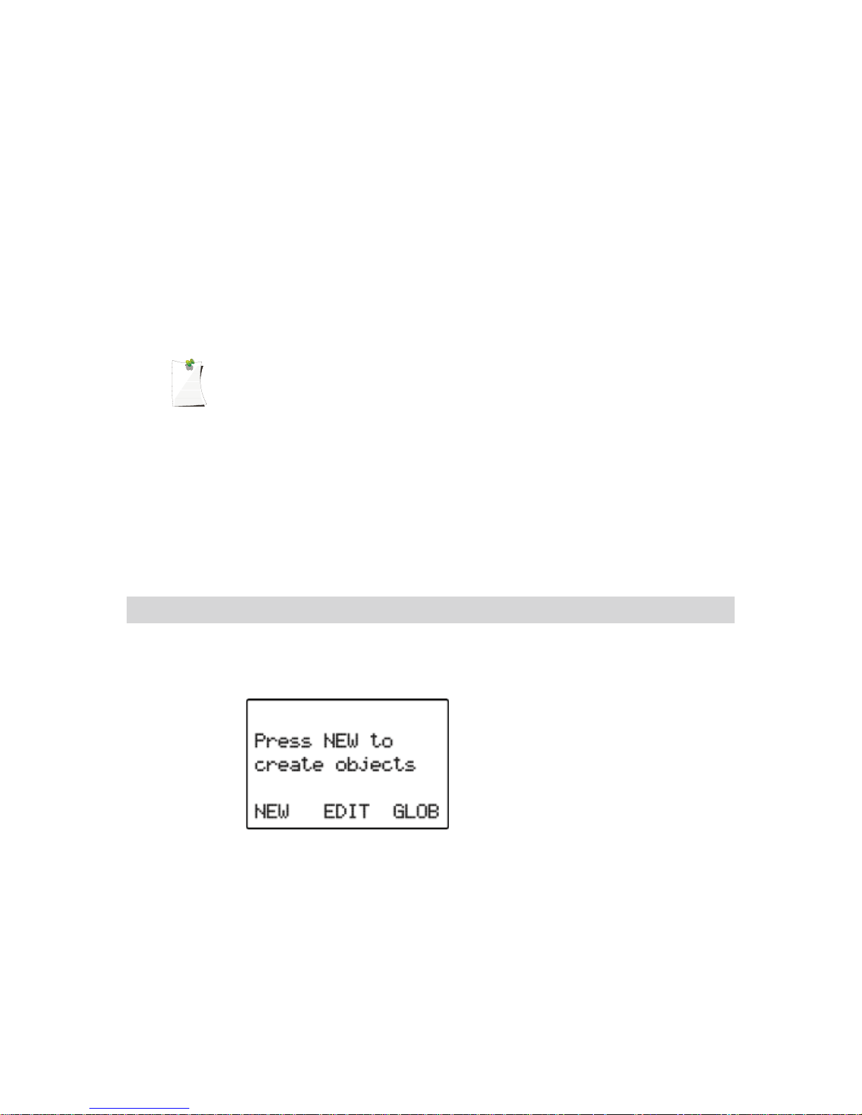
When the scanner is first turned on after it is unpacked, you are
working with a clean slate. You will notice that your scanner tells
you this:
The scanner is in program mode and is ready for you to enter the
first Objects into the memory. The scanner prompts you to
Press NEW to create objects.
You will also notice that there are three pushbutton keys beneath
the display, and above each button in the display, a label that
indicates the current function of these three keys. These keys
are called softkeys, and they function much like the softkeys on
0715 User Manual Page 20

many Automatic Teller Machines. Their meaning can change
depending on the operational state that the radio is in. Right now,
the softkeys on your radio should read as follows:
NEW EDIT GLOB
Let!s focus on the NEW softkey for a few minutes. As you might
have guessed, NEW is an invitation for you to create a new
Scannable Object (CONV, TGRP, LMIT, SRVC, or SWPR). So,
what would you like to create first? We suggest that you start
with a Conventional Channel Object (CONV) first, to get familiar
with the radio!s user interface and display.
Conventional Channel Object (CONV)
A Conventional Channel Object (CONV) is a record that stores
the parameters for a regular, non-trunked conventional AM or FM
channel. When you create a CONV object, you are creating an
object that will allow you to scan and monitor a “plain old radio
channel”, that is, a single frequency and the associated
parameters that are necessary for you to receive traffic on that
frequency.
Essential Conventional Channel parameters
CONV objects are the simplest objects supported by the radio.
By this we mean that there really isn!t that much for you to do if
you want to create one. There are only a few essential
parameters in the CONV object fields that must be set correctly
for a CONV object to work. The Frequency must be set to match
the frequency of the transmitter you want to scan or monitor, and
the MODE should be set to AU, or, if desired, AM, FM or NFM.
Note that the scanner will automatically select the default mode
based on the frequency you enter when MODE is set for AUto. In
most cases it will not be necessary to change this.
We also recommend that you label your CONV object by giving it
a name in the TAG field. This will make it easier for you to find
the CONV object later, and identify it when the scanner stops to
monitor activity. Enter your CONV object by following these
steps.
As we mentioned above, a brand new radio will launch into
Program Mode when it is first turned on, which allows for
creation and editing of Scannable Objects. If this is the first time
you have turned on your radio, you should see these softkey
labels at the bottom of your screen:
0715 User Manual" Page 21
NEW EDIT GLOB
If not, press the PGM (Program) key now.
Press the NEW softkey to begin entry of a new object.
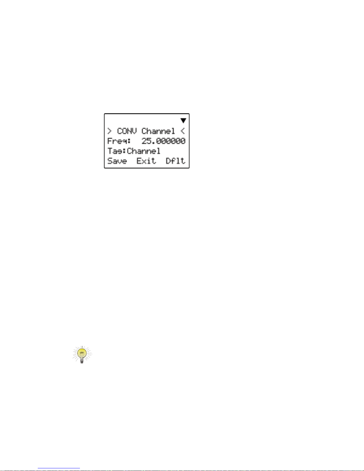
Press the CONV softkey to begin entry of a CONVentional
Channel object. Your scanner!s display should read as follows:
Now, take a moment and study the display. You will notice that
the ! icon is active. Its purpose is to indicate that you are at the
very top position of the menu for a conventional channel object,
and there are more parameters that can be accessed if you scroll
down. We also see three new softkeys:
Save Exit Dflt
The Save softkey will save your new CONV object to the file
system when pressed (but don!t press it yet!). The Exit softkey
aborts the creation of the new CONV object, and the Dflt
softkey restores the selected CONV menu parameter to its
default setting.
If you press the $ key on the bottom of the 5-way pushbutton
pad, you can scroll down and see all of the parameters that can
be specified for a CONV object. Go ahead and take a peek -
then scroll back to the very top of the display so you can begin
entering information for your first CONV object.
HINT: Pressing FUNC # or FUNC $ will jump to the top or bottom of a
menu, respectively.
Note that as you scroll both the upward and downward scroll
indicators will illuminate to indicate that there are parameters
above and below the current cursor position, until you get to the
very end of the menu, where only the upward scroll indicator will
be on to indicate that there are no more parameters below the
current cursor position. Also note that a few lines of context
sensitive help are available for each menu item. To see the help
0715 User Manual Page 22

text for a menu item, press FUNC then press SEL on the 5-way
pushbutton pad. To exit help, press SEL again.
With the scrollable window position so that the flashing cursor
appears next to the Freq: label, key in a known local frequency
and press the ENT key, or press the DONE softkey - either one
will do the same thing. There! You just entered the frequency for
your first CONV object.
By default, your new CONV object will be tagged “Channel”. If
you!d like to change this, just scroll the screen until the flashing
cursor highlights the Tag: field, then press
SEL to edit the tag.
You can move the cursor around using the the !" keys on the
5-way pushbutton pad, use the CL key to clear the old text, or
press FUNC CL to erase the entire field. To enter text, find the
letter you want to enter on the front panel of the radio, press the
numeric key beneath it, then press 1, 2, 3, or 4 depending on the
position of the letter in the group for that number. For example, to
enter FIRE, press:
3 3 F
4 3 I
7 3 R
3 2 E
Press the ENT key or DONE softkey to store the new tag
information for your CONV object.
Now you are ready to store your first CONV object. There are
other parameters that you can change, and we invite you to
scroll through the CONV menu to see the other settings that are
available. You can experiment with the different settings. If you
make a change that you aren!t certain about, press the Dflt
softkey to restore the setting to its original values.
When you!re ready, simply press the Save softkey to save your
new conventional object. Once the object is saved, you can
continue to enter other new objects, or press MAN to listen to the
CONV object you just entered, or SCAN to start scanning!
NOTE: Your scanner uses Scan Lists as a way to group objects together
according to your preferences for scanning. By default, all new
objects are placed in Scan List 01. There are a total of twenty regular
Scan Lists in your radio, a special Favorites Scan List, and a scan
list to hold Skywarn objects. Scan List membership for an object is
0715 User Manual" Page 23

assigned in the individual object menus. For now, just let your new
objects go to the default Scan List 01. Later in this section we will
show you how you can group your objects into Scan Lists.
Talkgroup Object (TGRP)
A Trunking Talkgroup Object (TGRP) is a record that stores the
parameters for a trunked talkgroup on a trunked radio system.
When you create a TGRP object, you are creating an object that
will allow you to scan and monitor a talkgroup on a particular
trunked radio system.
Essential Trunking Talkgroup parameters
As a standalone object, a TRGP object is really no more
complicated than a CONV object. The trunking system (TSYS)
that the TGRP is a member of must be specified. Each talkgroup
has a digital “address” on the trunking system, which is called the
talkgroup ID, and this must be provided. We also recommend
that you label your TGRP object by giving it a name in the TAG
field. This will make it easier for you to find the TGRP object later,
and identify it when the scanner stops to monitor activity.
Setting up and using a Trunking System (TSYS) object
We just mentioned that the TSYS is an essential parameter
needed in order for a TGRP object to function properly and
receive radio traffic. The TSYS object has its own set of essential
parameters, and these parameters vary depending on the type of
trunked radio system you plan to monitor. If you are a reasonably
experienced user you probably already know what the essential
parameters are for the system you wish to monitor. For example,
each TSYS must correctly specify the type of system being
monitored, the control channel or LCN frequencies used by the
system, and so on. A detailed description of each type of system
supported by this radio and the essential parameters required to
make the different types of trunked radio systems work properly
is provided in the Detailed Menu Reference. So, if all of this
makes sense to you then you should proceed and enter the
required data for the system you wish to monitor to make a new
TSYS as you create your TGRP. If not, please refer to the TGRP
section of the Detailed Menu Reference so that you will
understand which TSYS parameters are required for the type of
trunked radio system you wish to monitor.
The first time you make a TGRP, you must also create a TSYS
that contains the system parameters associated with the trunked
radio system itself. Once you create a TSYS object for a
particular trunked radio system, you can use the TSYS object
0715 User Manual" Page 24
over and over again without having to re-enter all of the system
data.
Assuming that you have already entered one or more CONV
objects (which we recommend you do prior to attempting the
entry of the slightly more complicated TGRP object), you should
press the
PGM key to place your scanner into Program Mode,
then press the NEW softkey, then press the TGRP softkey. Your
radio display should appear as follows:
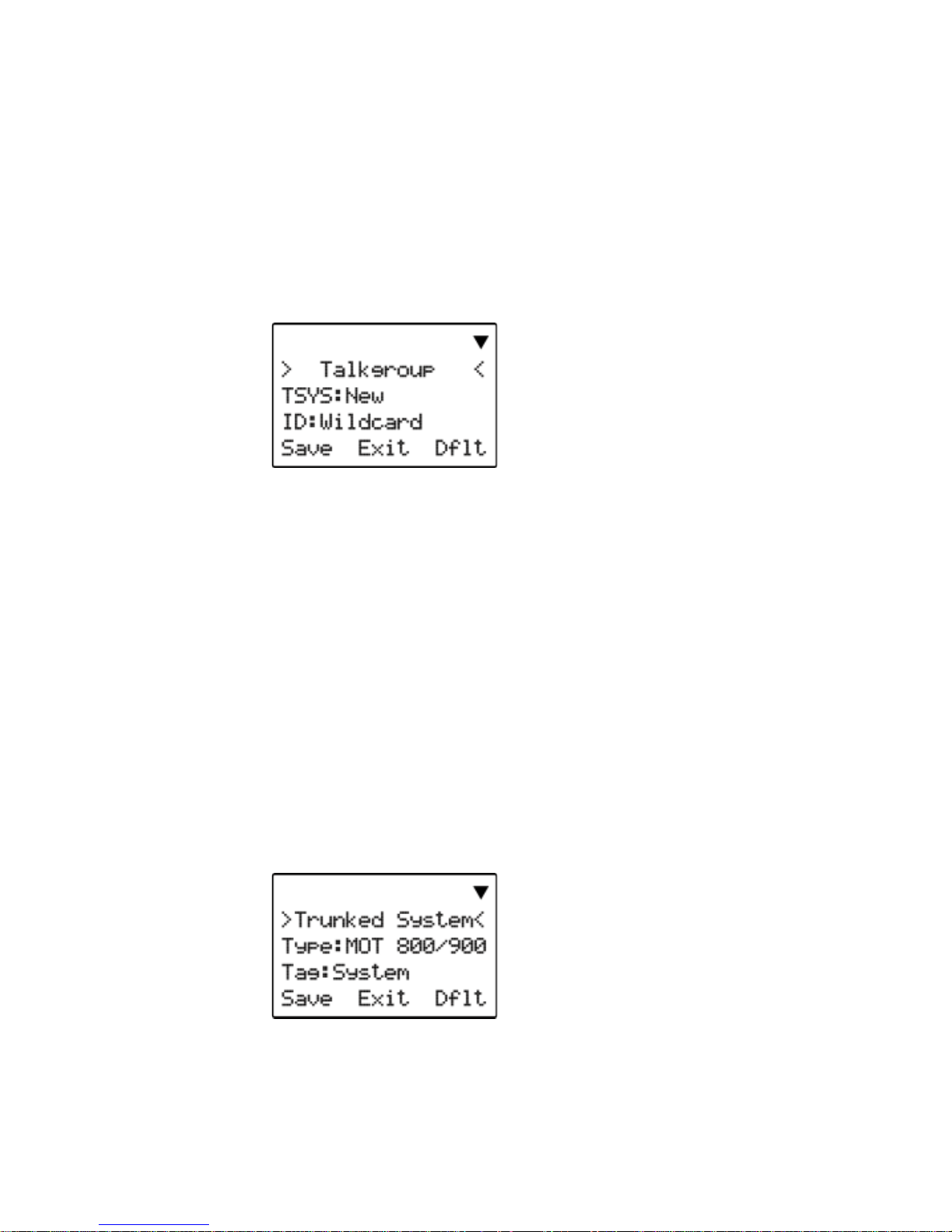
In the same way as with the CONV object, this menu of TGRP
parameters can be scrolled up and down to access and enter or
change the various parameters associated with a trunking
talkgroup.
For the purpose of this example, we will assume that you wish to
create a TGRP object for a Motorola Type II 800 MHz trunked
radio system, which is one of the more common types of trunked
radio systems in use. (If this is not the case, we encourage you
to refer to the Detailed Menu Reference section of this manual
for instructions that apply to the type of TSYS you wish to
monitor.)
If necessary, scroll the display so that the flashing cursor is
highlighting the TSYS field, then press the SEL key in the center
of the 5-way pushbutton pad. Your radio!s display should appear
as follows:
We are entering a new Motorola Type II 800 MHz system, so we
can leave the Type: field as-is. It!s a good idea (in fact, a
REALLY good idea, for reasons you will see as you proceed) to
0715 User Manual Page 25
scroll to the Tag: field and enter a name for the system using
the methods previously described for naming your CONV object.
We will use the tag MySystem for this particular example in the
documentation.
Next, scroll to the Frequencies: field to begin entering the
control channel frequencies for the MySystem trunked radio
system. Press the
SEL key, and at the Ch01: field you should
enter the first control channel frequency for your Motorola
trunked radio system. Simply key in the frequency including the
decimal point, and press the ENT key or the DONE softkey to
store the control channel frequency. Repeat this step to add any
other control channels used by the system. Typically, a Motorola
trunked radio site or system will have one active control channel
and three backup control channels. You need only enter the
active control channel for the scanner to track the system, but if
the system switches to a backup control channel the scanner will
not receive traffic unless the frequency for the backup control
channel has been entered.
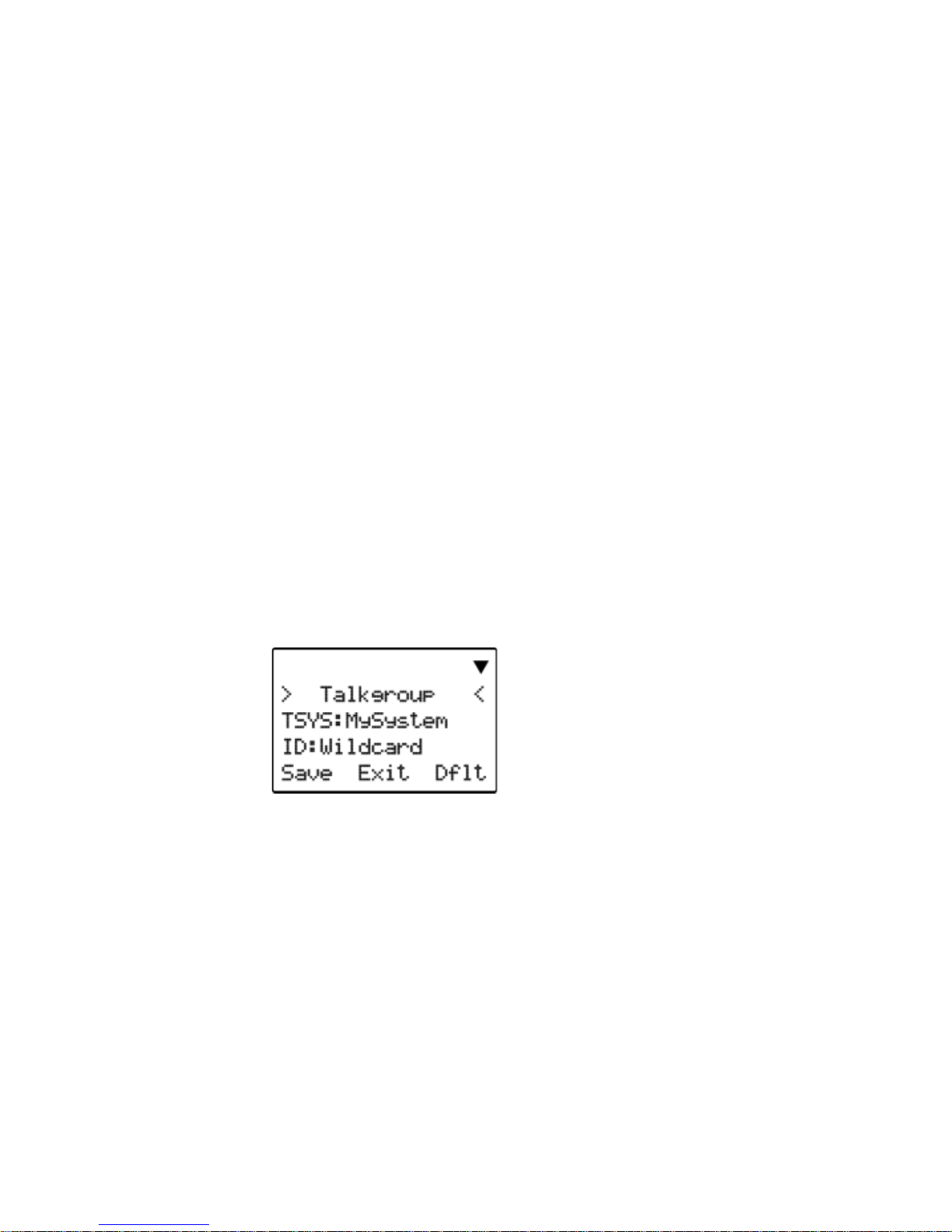
Once you have finished entering the control channels, press the
SAVE softkey. This will store the new TSYS into memory and
return you to the TGRP parameter entry. Your display will now
appear as follows:
Notice that the system name has changed to reflect the name
you chose when you were entering the parameters for the
trunking system. As you enter this TGRP and other TGRP
objects for this system, you will just specify the system name
here. So, the TSYS parameters for a system need only be
entered once. You simply specify the already-entered TSYS as
needed when building more TGRP objects for the same system.
Scroll down one click to the ID: field. Note that by default, the
trunking talkgroup ID is set to Wildcard. Wildcard is a special
type of TGRP object that allows you to monitor all talkgroup call
traffic on the associated trunked radio system. Wildcard TGRP
objects allow you to quickly find and store new or unknown
talkgroups on a trunked radio system. When a Wildcard TGRP
0715 User Manual Page 26
 Loading...