

Grech Motors G28, G33, G45 M2, EG40, G33D Owner's Manual
...
MOTORS
This label contains vital information used to identify your specic vehicle and the safety features
that must be understood and followed in order to operate this vehicle safely.
Your Grech Vehicle ID Number is:

MOTORS
Grech Motors
6915 Arlington Avenue Riverside, California 92504
(855)-994-7324 GRECHMOTORS.COM
Congratulations,
and thank you for purchasing a Grech Motors Vehicle.
You have taken ownership of a true luxury vehicle which is in a class all its own. We are
providing this manual to familiarize you with your new Grech Motors vehicle. This manual
shall serve as a reference document for the operations and maintenance procedures that
shall be required throughout the life of your vehicle. This edition covers all Chassis models,
and is designed to be used in conjunction with the original chassis manufacturer’s owner’s
literature, as well as all other component manufacturers literature.
IMPORTANT: PLEASE READ CAREFULLY
For your safety and the safety of others, we ask that you completely familiarize yourself with
this manual, and all other operators manuals before you operate this vehicle for the first time.
PLEASE NOTE: Updates to all manuals are online at GRECHMOTORS.COM
TABLE OF CONTENTS
SAFETY
Pre-Trip Inspection (suggested minimum) 6
General Vehicle Safety Warnings
Vapor Door Operational Safety Check List
Electric Door Emergency Release Lever
Emergency Egress Window Operation
Emergency Roof Hatch Exit 16
Dual Overhead Parcel Rack
OPERATION
Drivers Overhead Control Panel for F-550 & Freightliner 19
Drivers Dash Control Panel for E-450 20
PROAIR Control Panel 21
Audio/Video PA Control
Diesel Exhaust Fluid & Engine Brake 24
Water Fill Tank & Water for Lavatory
Lavatory Operations (if equipped) 26
Factory Suspension Dump System Operation 27
Auxiliary Battery Location
E-450 Heated Mirror Operation 29
Rear Step Operation
8
10
12
14
18
22
25
28
30
GRECH MOTORS
4
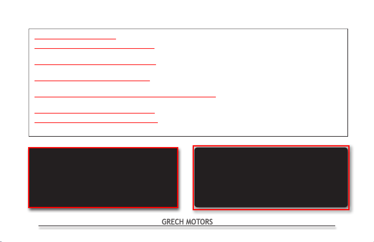
TABLE OF CONTENTS
CAUTION-ADVISORY Regarding Customer Vehicle Alterations
General Vehicle Dimensional Specications
Vehicle ID Labels
Customer Assistance
Wheels and Tires
Load Carrying Capacities
Ultra Ride Air Suspension
Firestone Ride Rite Air Spring
Kelderman Suspension
Preventative Maintenance
Basic Troubleshooting
E450 Vehicle Circuit Board Assembly
F550 Vehicle Circuit Board Assembly
Freightliner Vehicle Circuit Board Assembly
Vehicle Wiring Diagrams Online @ WWW.GRECHMOTORS.COM
Parts - Service - Warranty
Vendor Reference Listing
GRECH MOTORS Warranty Statement
31
32
33
34
37
58
63
64
65
66
70
73
75
77
79
80
84
85
GRECH MOTORS
5
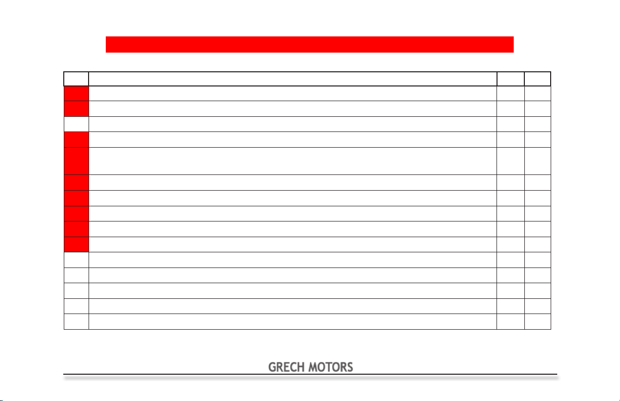
Pre-Trip Inspection (suggested minimum)
Any item not passing inspection, must be reported immediately, before operating vehicle
FAILURE OF HIGHLIGHTED ITEM(S) TO PASS INSPECTION WILL CAUSE VEHICLE TO BE GROUNDED
Item Inspection Procedure Pass Fail
1 Check preventative maintenance schedule for services due at present mileage
2 Calculate Load Carrying/Payload Capacity (See page 56 of this manual)
3 Check Side Passenger Entry Door - Emergency Exit Operation & Obstruction Sensing System
4 Check operation of drivers seat and seat belt
5 Check operation of steering wheel and shift levers
6 Check operation of turn indicators
7 Check operation of foot pedals and parking brake
8 Check operation of all gauges, for normal readings with engine running
9 Check operation of dash indicator lights with key on, engine not started, then again with
engine started
10 Check operation of ventilation system: heating, defrosters, fans and air conditioning
11 Check: horn, wipers, washers, and mirrors for cleanliness, adjustment, operation and
damage
12 Check condition of re extinguisher, warning reectors and rst aid kit
13 Check all doors, glass and windows for operation, cleanliness, and damage.
14 Check all emergency exits for operation, warning devices, markings, to be free and clear
15 Check interior lighting: for operation and damage
GRECH MOTORS
6
Pre-Trip Inspection (suggested minimum)
Any item not passing inspection, must be reported immediately, before operating vehicle
FAILURE OF HIGHLIGHTED ITEM(S) TO PASS INSPECTION WILL CAUSE VEHICLE TO BE GROUNDED
Item Inspection Procedure Pass Fail
16 Check Side Passenger Entry Door for damage and proper closing operation
17 Check exterior lighting for operation and damage
18 Check exterior for cleanliness, markings and damage
19 Check fuel cap in place and secure
20 Check all tires and wheels for tread depth, cracks & bulges, missing lug nuts, and air
pressure Frt 75 psi & Rr 80 psi for E-450, 95 psi for F-550, 110 psi for Freightliner
21 Check oil level
22 Check transmission uid level
23 Check engine coolant level
24 Check power steering uid level
25 Check brake uid level
26 Check belts for tension and wear
27 Check operation of cameras, if applicable
28 Check operation of PA system, if applicable
29 Check operation of audio and video system, if applicable
30 Check wheelchair lift for proper function or damage and securement station equipment
GRECH MOTORS
7
GENERAL VEHICLE SAFETY WARNINGS
NO STANDEES ARE ALLOWED, AT ANY TIME, WHILE THE VEHICLE IS IN MOTION.
DISCONTINUE OPERATION OF THE VEHICLE, IF ANY CRITICAL ITEM ON THE PRE-TRIP INSPECTION LIST FAILS TO
PASS, OR UNTIL ALL PROBLEMS HAVE BEEN RESOLVED.
DISCONTINUE OPERATION OF THE VEHICLE, IF THE DOOR WARNING BUZZER/DOOR AJAR LIGHT IS ILLUMINATED
WHILE VEHICLE IS IN MOTION.
IF A DOOR AJAR WARNING LIGHT IS LIT, CHECK ALL DOORS FOR PROPER CLOSURE. NEVER OPERATE THIS
VEHICLE UNTIL THE PROBLEM HAS BEEN RESOLVED.
THIS BUS IS NOT DESIGNED TO TOW ANOTHER VEHICLE OR TRAILER. DO NOT ATTEMPT TO TOW OR PULL ANOTHER
VEHICLE WITH THIS BUS.
DISCONTINUE OPERATION OF THE VEHICLE, IF ANY PERSON STANDS IN THE BUS WHILE THE VEHICLE IS IN MOTION.
DISCONTINUE OPERATION OF THE VEHICLE, IF A DOOR OR EMERGENCY EXIT SHOULD OPEN WHILE THE VEHICLE
IS IN MOTION.
GRECH MOTORS
8
Vapor Electric Door Operational Safety Check List
This vehicle is equipped with an Electric Actuated Passenger Door
made by Vapor/Wabtec
Electric Door Operation Safety Check List
ATTENTION
The vehicle user should conduct a daily check of each of the following systems when
operating a vehicle with an electric actuated passenger door.
Obstruction Sensing
The Obstruction Sensing System - (must be checked on a daily basis)
The electric actuated passenger door system is designed to detect an obstruction that may interfere with door’s
operation while closing. When the Obstruction Sensing System detects an obstruction while the door is closing, the
system will stop the door and then reopen it. After a brief delay, the System again will attempt to close the door. The
System will stop and reopen the door if it detects an obstruction again. If the System detects an obstruction on its
third attempt to close the door, it will stop with the door coming to rest in the open position. Pressing the door control
command button again (ref. pg 11 & 19) will allow the operator to resume the door closing process. If a problem
persists, call the Grech Motors Service Department at 1-855-994-7324
GRECH MOTORS
9
Vapor Electric Door Operational Safety Check List
The Obstruction Sensing System Test Procedure
The vehicle driver should test the Obstruction Sensing System every day before putting the vehicle into
service. To test the System, the vehicle driver should:
1. Activate the Door Command Button to move the door into its fully opened position.
2. While keeping the passenger doorway clear of objects and passengers, the vehicle driver should
create an obstruction in the doorway by placing a piece of wood or other debris in the door’s
path.
3. Next, the vehicle driver should attempt to close the passenger door by activating the Door
Command Button.
4. If the passenger door contacts the obstruction and fails to stop once it makes contact, call the
Grech Motors Service Department at 1-855-994-7324 and do not operate the vehicle.
5. If the passenger door stops and re-opens without seeming to contact an obstruction, call the
Grech Motors Service Department at 1-855-994-7324 and do not operate the vehicle.
6. If the passenger door contacts an obstruction, stops, re-opens and closes, and if it continues
repeating this process without stopping in the open position after the third cycle, call the Grech
Motors Service Department at 1-855-994-7324 and do not operate the vehicle.
7. If the passenger door fails to close when the operator puts the vehicle into gear, call the Grech
Motors Service Department at 1-855-994-7324 and do not operate the vehicle.
10
GRECH MOTORS
Vapor Electric Door Operational Safety Check List
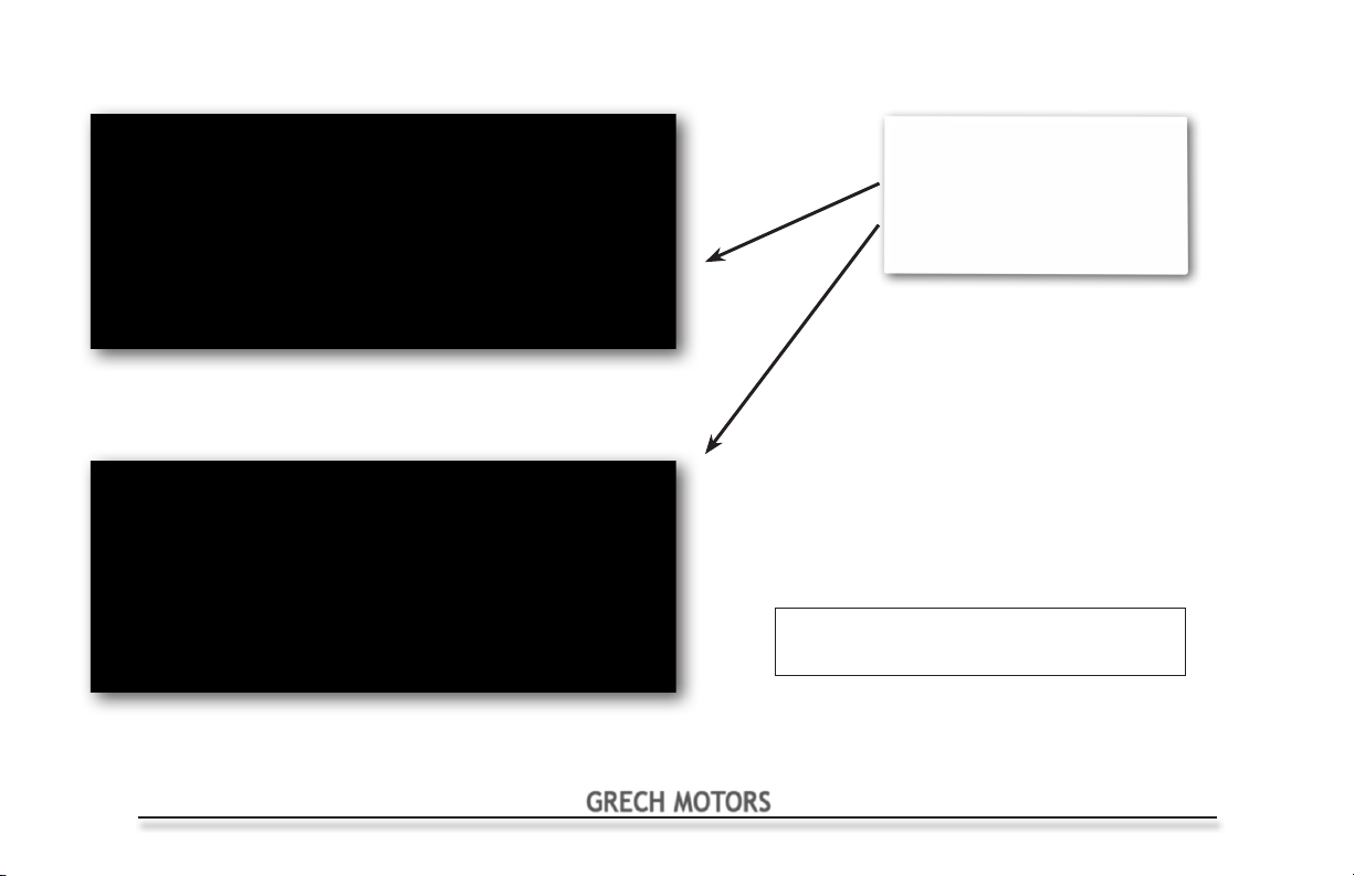
Auxiliary Door Switch door operation -
This vehicle is equipped with an Auxiliary Door
Switch. The Auxiliary Door Switch allows an
operator to open the passenger door when
outside the driver’s compartment. The Auxiliary
Door Switch is located on the pillar behind the
passenger seat in driver’s compartment.
The Emergency Release Lever
System
basis)
This vehicle is equipped with an Emergency
Release Lever that, when actuated, will allow
passengers to open the door. The Emergency
Release Lever System is actuated by moving
the RED HANDLE from right to left as indicated
on the sticker. See Photo No. 1 on page 13.
When the Emergency Release Lever is in
the left position, the door can be opened with
hand-pressure applied to push the door out
and away from the bus.
- (must be checked on a daily
Electric Door
Side Entry Door in the
un-locked Position
Side Entry Door in the
locked Position
GRECH MOTORS
11
Electric Door Emergency Release Lever
Electric Door
The vehicle driver should test the Emergency Release Lever (ERL) System every day before putting the vehicle into
service. To test the System, the vehicle driver should:
1. Actuate the Emergency Release Lever by moving the red handle from the right to the left.
See Photo No. 1 on page 13.
2. Open the door by pushing it out and away from the coach.
3. When released, the door should move freely and with minimal pressure away from the coach
and into the door’s fully open position.
4. After determining the door opens freely, return the door to its closed position and re-engage the
Emergency Release Lever by moving the red-handle from the left to the right. See Photo No. 2
on page 13.
5. Conrm that the red-handle moves from the right to the left, and from the left to the right, without
obstruction. If the red-handle does not move smoothly and without obstruction, call the Grech
Motors Service Department at 1-855-994-7324 and do not operate the vehicle.
6. Conrm that the Emergency Release Lever is in the right position, that it engaged and secured
the door against the coach. While the ERL is in the closed and locked position, because the red-
handle is in the right position, attempt to push against the door as if to open it. The door should
not move. If the door moves while the red-handle is in the right position, call the Grech Motors
Service Department at 1-855-994-7324 and do not operate the vehicle.
7. The vehicle should never be driven with the Emergency Release Lever in the left or forward
position.
12
GRECH MOTORS
Electric Door Emergency Release Lever
Electric Door Release Lever- Exit Position
Photo 1
Emergency Exit Lever Decal
CAUTION!
LEVER MUST BE CHECKED
DAILY, PRIOR TO VEHICLE
OPERATION
EMERGENCY USE ONLY
Electric Door Release Lever- Closed Position
Photo 2
GRECH MOTORS
13
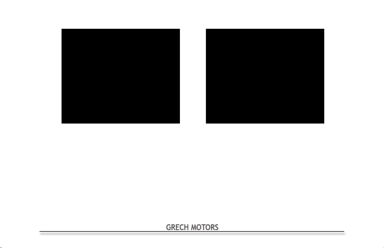
Emergency Egress Window Operation
14
Handle in Closed Position
Windows with Emergency Exit stickers are designated
Emergency exits. Follow the directions on the sticker.
Rotate Handle and push window out.
This vehicle is equipped with (multiple) Emergency Egress Windows. These windows serve as supplemental exit
points in the event of an emergency. The vehicle has (multiple) Emergency Egress Windows on the passenger side
and the driver’s side of the vehicle.
The Emergency Egress Windows are a vital component in the vehicle’s emergency exit system. As such the vehicle
driver should test the Emergency Egress Window Operation every day before putting the vehicle into service.
To test the System, the vehicle driver should check the following items:
Photo 1
CAUTION!
Check Exit Operation, Daily.
Handle in Open Position
Photo 2
GRECH MOTORS
Emergency Egress Window Operation
1. Each Emergency Egress Window is marked by an Emergency Exit sticker on the right side of the window,
half way up, next to the Emergency Handle. Conrm that each Emergency Egress Window is equipped
with the sticker designating that window as an emergency exit. If the Emergency Egress Window is
missing the Emergency Exit designation sticker, call the Grech Motors Service Department at
1-855-994-7324 and do not operate the vehicle.
2. Each Emergency Egress Window is secured by one latch, on the right side of the window, half way up.
Actuate the Emergency Egress Window by rotating the handle as shown in Photo No. 2 on page 14.
The latch is in the released position when the handle moves from the vertical to the horizontal position,
and releases the window to be pushed open.
3. When Emergency Egress Window Latch is released, the user can open the window by pushing on the
bottom of the window frame. The Emergency Egress Window should swing out and away from the
vehicle.
4. If the Emergency Egress Window does not swing open when the latches are released and the window
frame is pushed, call the Grech Motors Service Department at 1-855-994-7324 and do not operate the
vehicle.
5. When properly closing the Emergency Egress Window back to a secured position, the handles will return
to the vertical locked position. Each latch should be in the locking position when the user moves the latch
to the vertical position. Check to ensure the Emergency Egress Window is secured against the coach by
pushing against the window frame while the latch is in the locked vertical position.
Front Windshield Caution!
It is highly recommended that decals not be used on the front windshield. The use of decals
may cause discoloration over time, and thereby permanently discolor the area beneath the decal.
GRECH MOTORS
15
Emergency Roof Hatch Exit
SUGGESTED MAINTENANCE
Periodically inspect attaching fasteners for evidence of
loosening due to tampering, and regularly clean surface
with a mild soap and water.
CAUTION: When removing grafti, it is the customers
responsibility to ensure cleaning solutions are
compatible with the materials used on Safety Vents.
Solutions containing, acetone, ether, lacquer thinner, or
other solvents can destroy the high strength properties
of many engineering plastics - AVOID these cleaners
ABOVE, THEN PUSH TO OPEN
TURN HANDLE AS SHOWN
16
SEE MANUFACTURERS LITERATURE
FOR ADDITIONAL INFORMATION
CAUTION!
Check Exit Operation, Daily.
GRECH MOTORS
Emergency Roof Hatch Exit
All vehicles under 45ft are equipped with one Emergency Roof Hatch, 45ft vehicles have (2) hatches. This hatch serves
as a supplemental exit point in the event of an emergency. The Emergency Roof Hatch is located in the vehicle’s roof,
above the passenger walkway.
The Emergency Roof Hatch is a vital component in the vehicle’s emergency exit system. As such the vehicle driver
should test the Emergency Roof Hatch every day before putting the vehicle into service. To test the System, the vehicle
driver should check:
1. Ensure that each Emergency Roof Hatch is marked by an Emergency Exit sticker. Confirm that the Emergency Roof
Hatch is equipped with the sticker designating the hatch as an emergency exit. If the Emergency Roof Hatch Exit is
missing the Emergency Exit designation sticker, call the Grech Motors Service Department at
1-855-994-7324 and do not operate the vehicle.
2. Each Emergency Roof Hatch is secured by one latch. Actuate the Emergency Roof Hatch by turning its handle from
the “LATCHED” position See Photo No. 1 on page 16 to the “TO EXIT” position. See Photo No. 2 on page 16.
3. When Emergency Roof Hatch latch is released, the user can open the hatch by pushing it away from the vehicle. The
Emergency Roof Hatch should swing out and away from the vehicle.
4. If the Emergency Roof Hatch does not swing open when the latch is released and the hatch is pushed, call the
Grech Motors Service Department at 1-855-994-7324 and do not operate the vehicle.
5. Close Emergency Roof Hatch and secure it by returning the handle to the “LATCHED” position. Check to ensure the
Emergency Roof Hatch is secured against the coach by pushing against the hatch while the handle is in the
“LATCHED” position.
GRECH MOTORS
17
Overhead Parcel Rack
Overhead Parcel Rack
CAUTION!
Do not overload Parcel Racks.
Do not fasten parcels to retainer
bars.
Note: Maximum loading specication for
both model parcel racks is either 20 Lbs.
per foot or 5 Lbs per passenger.
18
GRECH MOTORS
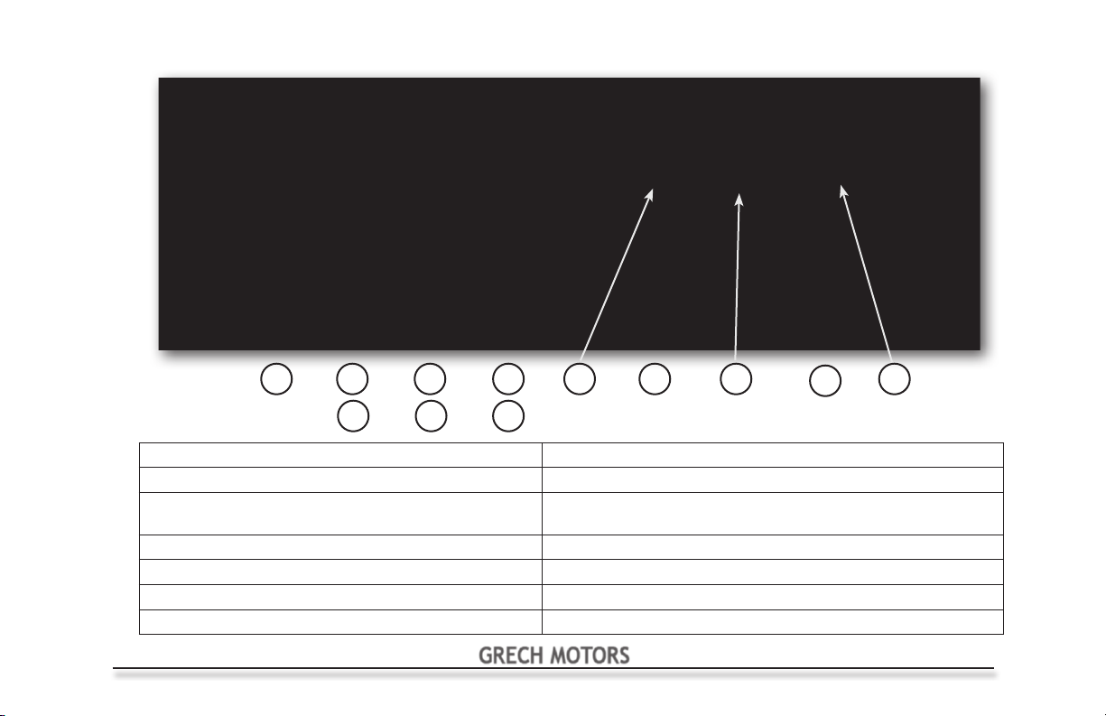
F-550/Freightliner Drivers Overhead Control Panel
2
3
1 Door Switch (open or close passenger door) 8 Climate Control Temperature Adjustment (Up or Down)
2 Door Ajar (
3 Reading Lights (optional) Note: Cool mode = A/C on both front & rear
4 Rear Door Ajar (
5 Interior Lights 11 Climate Control Mode Switch (Air - Heat - Off)
6 Exits (
7 Auxiliary
WARNING DEVICE
WARNING DEVICE
WARNING DEVICE
) 9 Climate Control Switch (Auto Mode) On or Off
) 12 Climate Control Fan Speed (High - to - Low)
41 8
5
) 10 Climate Control Temperature (Setting Point)
6
7
See page 21 for more PROAIR operating instructions
Heat mode = Heat from front unit only (on early models)
9
10
11
12
Note: 4 sec. after setting,
reading shows cabin temp
GRECH MOTORS
19
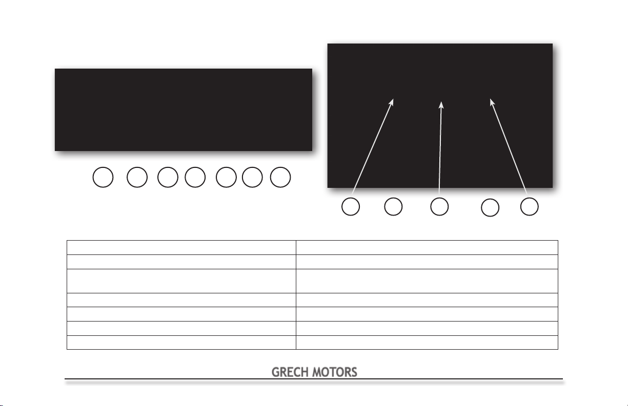
E-450 Drivers InDash Control Panels
742 53 61
20
8
9
10
11
See page 21 for more PROAIR operating instructions
1 Door Switch (open or close passenger door) 8 Climate Control Temperature Adjustment (Up or Down)
2 Reading Lights (optional) 9 Climate Control Switch (Auto Mode) On or Off
3 Interior Lights Note: Cool mode = A/C on both front & rear
4 Auxiliary 10 Climate Control Temperature (Setting Point)
5 Door Ajar (
6 Rear Door Ajar (
7 Exits (
WARNING DEVICE
WARNING DEVICE
WARNING DEVICE
) 11 Climate Control Mode Switch (Air - Heat - Off)
) 12 Climate Control Fan Speed (High - to - Low)
)
Heat mode = Heat from front unit only (on early models)
Note: 4 sec. after setting,
reading shows cabin temp
GRECH MOTORS
12
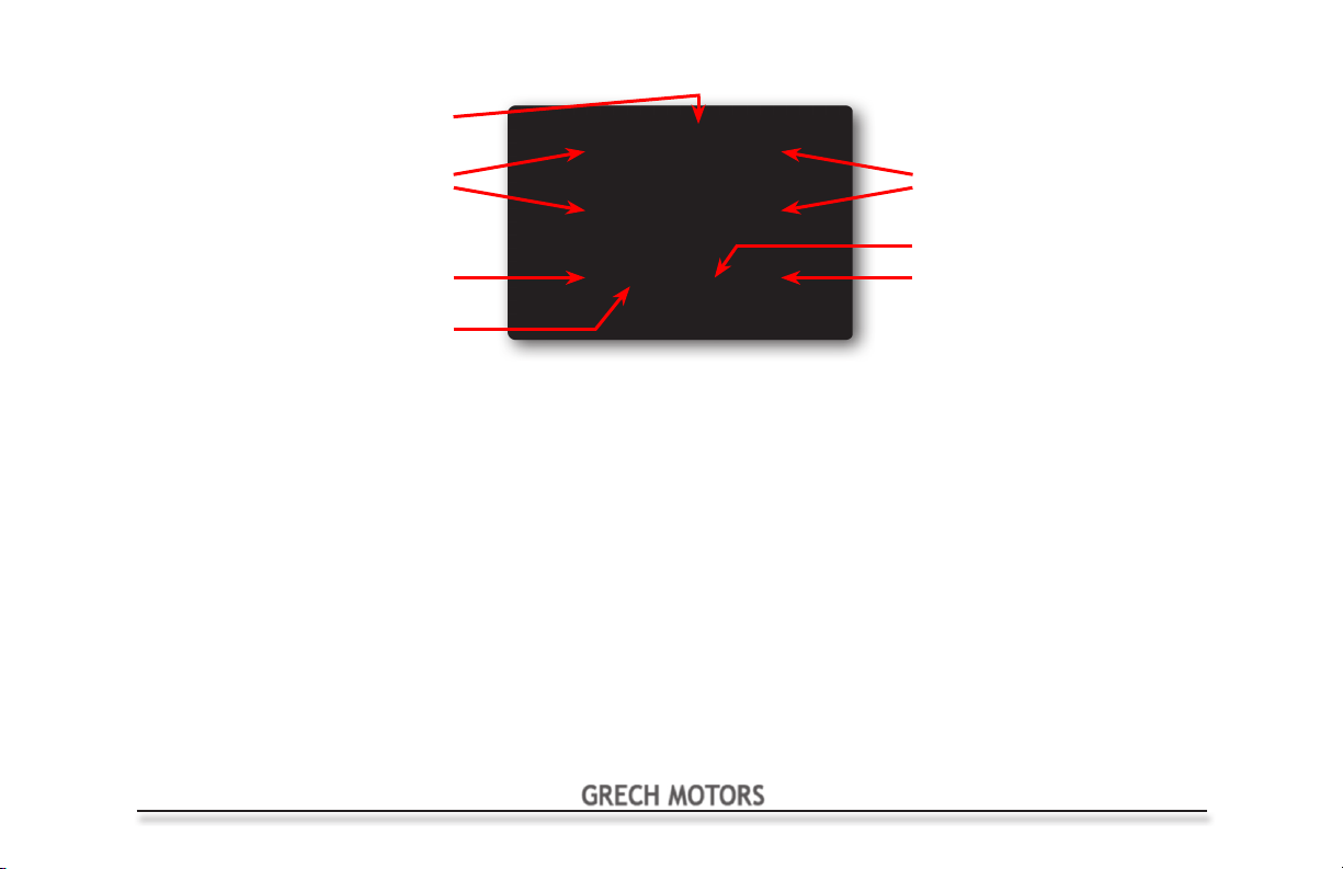
Temperature & Blower
Speed Display
PROAIR Control Panel
Temperature Set
Automatic Control
On Off
Automatic On Light
Mode Selector Push once for A/C, push again for heat and push once more to turn off.
A/C Mode Display on, reads and displays probe temperature, blower motor operates. Constant signal from A/C relay above set
temperature point and signal off below set temperature point. A/C light will be on.
Heat Mode Display on, reads and displays probe temperature, blower motor operates. Constant signal from heat relay below set
temperature point and signal off above set temperature point. Heat light will be on.
Blower Speed Select desired blower speed by pressing the up or down arrows, display will indicate set speed, F1 to F3 for the three speeds
of operation.
Temperature Temperature can be set by using the up/down buttons to select the desired level between 50°F and 99°F or 10°C and 37°C.
Display will show set temperature for two or three seconds then display will show actual temperature. To switch between
Fahrenheit and Celsius press both temperature up and down buttons at the same time for three seconds.
Auto Mode With A/C or heat on press auto to turn on auto 1 or auto 2 temperature control, press once more to shut off. In auto 1 mode
temperature is maintained + or - 2° and blower speed is manually set. In auto 2 mode temperature is maintained + or - 2° and
blower speed is automatic and cannot be changed. To switch between auto 1 and auto 2 press and hold temperature up
button then press and hold auto button for three seconds. Display will show current auto mode (A1 or A2) then switch to the
other mode (A2 or A1) .
Preset Operations Upon cycling of 12vdc supply, the unit will default to previous settings mode and blower speed. All output signals are negative
voltage.
Blower Speed
A/C & Heat Lights
Mode Selector
GRECH MOTORS
21

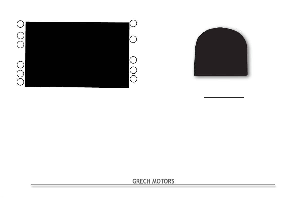
Audio/Video PA Control & Back-Up Camera
1
2
3
4
1. EJECT: Press to eject CD or DVD.
2. MENU: Press from inside any app to return to the main menu.
3. POWER: Press to turn on. Press and hold to turn off. While on,
quickly press to activate mute.
VOL: Rotate to adjust volume output.
4. USB/AUX-IN:
AUX cable for audio playback.
5. MAIN MENU: Tap any app icon to open that app. Swipe from
right to left, or tap "Next" at bottom of screen, to go to second
menu page.
6. SOURCE: Tap to return to main menu.
7. PRESET BANK: Tap to tune to indicated preset channel.
8. CURRENT RADIO STATION
9. AUTO SCAN/PRESET SCAN:
currently stored Presets. Press and hold to scan and store
strongest stations in your area.
22
Connect a USB flash drive, Apple iPod, or 1/8"
Tap to scan through
5
10. PROGRAM TYPE: Tap to view list of program type categories. Select a
category and tap search to find next available station in the category.
11. SAVE: Tap to store the currently tunned channel to a preset location.
12. DISTANCE:Tap to select and activate local and distance station reception-
local scans for strongest stations, distance scans for weaker stations.
13. DIRECT ENTRY: Tap to manually enter in desired station.
14. EQUALIZER: Tap to bring up and adjust audio settings.
15. TUNNING: Tap to tune station up or down.
16. BAND: Tap to change the current FM/AM band (FM1, FM2, FM3, AM1, AM2)
17. CURRENT BAND/PRESET
6
7
8
9
10
GRECH MOTORS
PLEASE SEE THE MANUFACTURERS LITERATURE
FOR ADDITIONAL OPERATING INFORMATION
11
12
13
14
17
16
15
Navigation Operating Instructions
1
Audio/Video PA Control & Back-Up Camera
11
2
10
3
9
4
5
6
1. MULTIPOINT ROUTE: Tap to create a multipoint route by entering waypoints and a final
destination.
2. NEW ROUTE: Tap to create a new route by entering the desired destination.
3. ADD WAYPOINT: Tap to add a waypoint to the current route.
DETOURS & ALTERNATIVES: Tap to find alternative routes, make detours and avoid
specific roads on the current route.
4. STAR: Tap to create route to a favorite location.
5. SPEAKER: Tap to change voice volume.
6. 2D/3D: Tap to switch between 2D top down view or 3D angled view.
7. PAUSE: Tap to pause or resume route guidance.
8. PROFILE: Tap to create and switch between profiles.
9. DELETE ROUTE: Delete the current route or next waypoint.
10. SETTINGS: Tap to change your preferences for route calculation, sound settings,
warnings and more.
11. USEFUL INFO: Tap to find information about current location, nearby help, country
details, trip data, sunrise and sunset times, and GPS satellite details.
8
7
CAUTION: In the event of power loss, Navigation System must
be reset to "Bus" mode in the settings menu.
GRECH MOTORS
Back-Up Camera
(located on rear of vehicle)
System Operation
This system consists of two major
components:
1. LCD Monitor within the Jensen-JRY9000
2. Back-Up Camera
The system may be connected two ways:
1. Fully manual, requiring the power
button on the LCD Monitor to be pushed
to energize the system and activate the
monitor.
2. Automatic, which activates the
monitor whenever the ignition is turned to
accessory or the engine is started and in
reverse.
23
Diesel Exhaust Fluid (DEF) & Engine Brake
Diesel Exhaust Fluid (DEF)
The new diesel mid-size bus requires Diesel Exhaust Fluid. The
Operator should monitor the DEF level on the dash (LED lights below
the fuel gauge - on Freightliner only) and replenish the DEF uid as
needed. It is never acceptable to run the vehicle out of DEF.
Freightliner Gauge
Ford Level Indicator
DEF Fill
Engine Brake
The new mid-size Freightliner bus is equipped
with an exhaust engine brake.
The switch to turn it on/off is
below the transmission gear selector.
EG Luggage
Compartment
Unlock Switch
24
GRECH MOTORS
Filling Water Tank & Water for Lavatory
Filling the Water Tank
Use the following steps to ll the water tank which supplies water to the lavatory
Open the
Water Fill
compartment.
Remove cap on fill neck.
Insert hose into fill neck.
Turn on water, water comes
out of overflow when full.
Turn off water.
Water for the Lavatory
The lavatory water pump
switch must be in the “ON”
position in order for the toilet
to ush and for water to be
supplied to the sink.
Note: Never run the pump
dry. Damage to the pump
will occur.
Pump Switch
Note: EG Water Fill
located behind
rear license plate
GRECH MOTORS
Water Fill
Note: When you are done lling the tank,
replace the cap and close the Water
Hose compartment Door.
Low Water Indicator
Note: Water pump will not
operate when Low Water
Indicator is iluminated.
Over Flow
25
Lavatory Operation (if equipped)
Dumping the Lavatory
Use the following steps to dump the lavatory on the bus. You should always wear rubber gloves and a face guard (or glasses/goggles) when
dumping the lavatory.
Step 3
Step on the toilet ush and allow the
water to run to ush the tank.
26
Step 1
Remove the sewer
hose from the storage
compartment.
Note: The sewage tank hose
must be drained into an
approved sewer drain only.
Never empty on the ground.
Step 2
Place the end of the hose in an
approved sewer drain. Then,
hook the hose to the dump valve
which is located under the bus
behind the right drive tire. Now it
is OK to open the valve.
Step 4
Close the valve, rinse the hose and return it to the storage compartment.
You should also rell the fresh water tank as outlined in the Filling the
Water Tank section.
GRECH MOTORS
Factory Suspension Dump System Operation
This in-dash switch
located to the right of the
dash cluster operates
the dump suspension
system.
CAUTION!
Only in emergency situations should the
vehicle be moved with the Suspension System
in dump mode.
CAUTION!
Check the surrounding area before using this
system to ensure it is safe to lower the vehicle.
CAUTION!
If the vehicle is moved with the Suspension
Rear Baggage Door Dump Switch
This switch is part of the Suspension
Dump system and is located inside the
baggage compartment. It operates the
dump suspension system to lower the
rear for easy access to the baggage
compartment.
Note: This system will only operate when
the ignition in the “on position”
Note: The suspension will automatically
raise to vehicle ride height when the rear
luggage door is closed.
System in dump mode, the suspension may
be damaged and/or create an unsafe driving
condition. This should never be attempted
unless in an emergency situation.
GRECH MOTORS
27
 Loading...