

Greaves 3G11 Series, 4G11 Series, 6G11 Series Operation And Maintenance Manual
OPERATION AND MAINTENANCE MANUAL
3G11, 4G11 and 6G11 Series of engines
GREAVES COTTON LTD.
Diesel Engines Unit,
Chinchwad, Pune 411019, India,
Tel: (91) – 20 – 27473564, 267308200
Fax: (91) – 20 – 27472276
Mail-ID:-gensetcare@greavescotton.com
Visit us: - www.greavescotton.com

Operation and Maintenance Manual
For
3G11, 4G11 and 6G11 Series Engines
3G11 Series Engine
4G11 Series Engine
6G11 Series Engine

Operational and Maintenance Manual for G11 Series Engines
Foreword
We thank you for choosing Gr eaves G11 series engine for your applica tion. G11 series engines are watercooled, four-strok e, multi-cylinder, direct injection compression ignition engines . The engines are designed
using modern concepts. The engines are suitable for various off-road applications. In addition to the
performance param eters the engine des igners have p aid special attention to ease of m aintenance, ease of
assembly and disassembl y, reliability and standardization.
The engines are com patible with existing em ission norms and are capable of achievi ng the future emiss ion
norms. The rigid construct ion of engi ne has reduc ed the noise and vibration to a very low level. This manual
describes the opera ting instruction and maintenance schedules of the engine. It is necess ary that manual
needs to be read carefully before putting the engine into operation.
Good installation, cle an water, air, lub e oil, fuel and ti mely maintenanc e will enh ance the life of your engine,
reduce your running cost a nd reduce the down time. We would like to emphas ize the use of only genuine
spare parts for the engine. Use the services of onl y authorized service dealer for maintenance. Use only
listed lube oils, water additives. Training facility is also available with Greaves where technicians can be
trained.
Continuous improvem ent m ay cause changes in this manual. In case the cha nge is im portant, we make it a
point to inform the owner s of the engin e. This m anual is regu larl y updat ed to include these cha nges. In case
of any queries, problems do not hesitate to contact our service dealer, regional office.
GREAVES COTTON LTD.
Diesel Engines Unit,
Chinchwad, Pune 411019, Indi a,
Tel: (91) – 20 – 274735 64, 2673 082 00
Fax: (91) – 20 – 27472276
Mail-ID:-gensetcare@greavescotton.com
Visit us: - www.greavescotton.com

Operational and Maintenance Manual for G11 Series Engines
Warranty Policy
Warranty Pol icy for Diesel Engine
A. Warranty Policy (Diesel engines)
Greaves Cotton Ltd. warrant y for the machinery is
limited to its faulty design, defective materials/
components and/or workman-ship and is valid until
a period of 15 months from the date of dispatch of
machinery from its W orks/Warehouse or one year
from the date of commissioning or completion of
3500 hours of operation, whichever event shall
occur first.
OR
Greaves Cotton Ltd. warrant y for the machinery is
limited to its faulty design, defective materials/
components and/or workman-ship and is valid unti l
a period of 24 months from the date of dispatch of
machinery from its Works/Warehouse or 18
months from the date of commissioning or
completion of 5000 hours of operation, whichever
event shall occur first provided the user of the
machinery uses recommended genuine spare
parts including “Greaves Maxtherm“ Lube Oil &
Coolant wherever applicable and use of genuine
Air Filter element and Lube Oil Filter element
purchased only from Authorized Dealers of
Greaves Cotton Ltd.
The foregoing warranty is not applicable in the
event, interalia, if:
• The machinery has been stored im proper ly
and not protected from adverse weather
conditions of any nature.
• Assembly of the Gen set is not carried o ut
as per the recommendation.
• Canopy manufactured and supplied along
with the D G Set is not as per the CPCB
approved drawings.
• If GOEM has his own approved design
through authorized agencies and is
adversely affecting performance of engine.
• If the D G set is installed and is in use
without approved acoustic enclosure
(canopy).
• The machinery has not been installed
strictly as per the recommendations of
Greaves Cotton Ltd. and operated in
accordance with the ins tructions contained
in the Greaves Cotton Ltd. operational
manual.
• The defective/improper fuel, lubricants,
coolants and any of their associated
systems are utilized
• Unauthorized person carries out repairs
and alterations.
• The maintenance of the machinery is not
strictly done as per the procedure detailed
in Greaves Cotton Ltd. operator’s
handbook/instruction manual.
• Improper tools and equi pments are u tilize d
at any stage during erection,
commissioning and maintenance.
• During operation, the eng ine is improperly
shut down or happened to over speeding
or is subjected to misuse, negligence or
accident.
• Failure in any way results from use of
components / parts not manufactured or
not authorized by us for use on our engine.
• If the engine is improperly stored beyond
period of six months without recomm
ended
l
ong storage treatment and used without
recommended de-preservation.
• The warranty shall not apply to fair wear
and tear of the individual components or
damages due to the negligence or
improper handling b y the purchaser or his
employees or agents or due to dam age by
any cause beyond our control.
• The warranty does not apply to defect
arising due to default in periodic preventive
maintenance and lapse in the use of

Operational and Maintenance Manual for G11 Series Engines
recommended spare parts including Lube
Oil & Coolant wherever applicable.
B. Terms of warranty
• The components having shelf life like
rubber components, belts, hoses and
replacement filters / consumables which
are normally maintenance spares are not
covered within the scope of this warranty.
• In cases of complaints on proprietary
bought out items, our warrant y is limited to
the extent of warranty of the manufacture.
• All goods are supplied on the condition
that under no circum stances we under tak
e
l
iability for the indirect or consequential
loss or damage of any nature.
• Warranty in respect of f ollowing items will
be restricted to 1000 hours of operation or
Three months, whichever shall occur first.
• Meters, battery charging alternator
components & indicating instruments,
Protection relays and control fuses
• Claim under warranty shall be summarily
rejected if the defects are not notified
within warranty period specif ied above a nd
lodged within 3 days of the expiry of the
warranty period.
• The new or repaired part of parts will be
delivered free of cost Ex-wor ks Chinch wad
Pune. Any additional delivery cost to be
borne by the purchaser.
• In respect of any warrant y claim accepted
by us, we shall arr an ge to replace or repair
relevant and respective parts free of cost
to the customer. If parts are replac ed, the
defective part shall be property of G reaves
Cotton Ltd. In any case, wherever the
parts are supplied with free charges,
Greaves Cotton Ltd. sha ll not be liable for
any fitment and / or other charges.
• Greaves Cotton Ltd. shall not be
responsible for replacement of the
c
omplete unit under an y circumstances. In
case of any warranty claim, the
responsibility of Gr eaves Cotton Ltd. shall
be limited to the defective parts.

Table of Contents
Page No.
Preface ....................................................................................................................................................... i
Warranty policy ........................................................................................................................................ ii
Modification summary ............................................................................................................................ iii
Table of contents ..................................................................................................................................... iii
Section 1.General............................................................................................................................. 1
1.1 Safety .................................................................................................................................... 1
1.2 Operation Guidelines .............................................................................................................. 1
1.3 Maintenance Guidelines ......................................................................................................... 1
Section 2. Engine Description ......................................................................................................... 2
2.1 Engine Orientation of 3G11 Series Engine ............................................................................. 2
2.2 Cylinder Nomenclature ........................................................................................................... 2
2.3 Engine Orientation of 4G11 Series Engine ............................................................................. 2
2.4 Cylinder Nomenclature for 4G11 engine ................................................................................. 2
2.5 Engine Orientation of 6G11 Series Engine ............................................................................. 2
2.6 Cylinder Nomenclature for 6G11 engine ................................................................................. 2
2.7 Engine Nameplate .................................................................................................................. 3
2.8 Location of the Nameplate ..................................................................................................... 3
2.9 Engine nomenclature system ................................................................................................. 3
2.10 Engine Techical Specification ............................................................................................... 4
2.11 Engine Illustrations for 3G11 Series Engine .......................................................................... 6
2.12 Engine Illustrations for 4G11 Series Engine.......................................................................... 7
2.13 Engine Illustrations for 6G11 Series Engine.......................................................................... 9
2.13.1 Engine Illustrations for 6G11 Series Engine ..................................................................... 10
2.14 Dimensions and weight – 3G11 Series Engine .................................................................... 11
2.15 Dimensions and weight – 4G11 Series Engine .................................................................... 11
2.16 Dimensions and weight – 6G11 NAx ................................................................................... 11
2.17 Engine Lifting Instructions ................................................................................................... 11
2.18 Transport, packing and storage .......................................................................................... 12
2.18.1 Safety notes for transport ................................................................................................ 12
2.18.2 Transport inspection ........................................................................................................ 12
Section 3. Systems ......................................................................................................................... 13
3.1 Lubrication System .............................................................................................................. 13
3.1.1 Engines lubrication system ............................................................................................... 13
3.1.2 Permissible engine inclination ........................................................................................... 14
3.2 Engine Cooling Systems ...................................................................................................... 15
3.2.1 G11 – Series Engine Cooling System .............................................................................. 15
3.2.2 G11 – Series Cooling System Data .................................................................................. 16
3.2.3 Water Specification .......................................................................................................... 16
3.2.4 Coolant Additives Specification......................................................................................... 16
3.2.5 Filling Up Coolant on A New Installation ........................................................................... 16
3.2.6 Topping up Coolant In An Already Installed Engine........................................................... 16
3.2.7 Draining the System ........................................................................................................ 17
3.2.8 Thermostat Element Replacement ................................................................................... 17
3.2.9 Water Pump..................................................................................................................... 18
3.2.10 Cleaning Radiator / CAC ................................................................................................ 18
Section 4. Fuel System .................................................................................................................. 19
4.1 G11 – Series Engine Fuel System ....................................................................................... 19
4.2 Trapped Air Removal from the System ................................................................................. 20
Section 5. Electrical Systems ........................................................................................................ 21
i

5.1 Starter / Alternator ................................................................................................................ 21
5.2 Electrical Control Panel ........................................................................................................ 21
5.3 Battery ................................................................................................................................. 21
5.4 Alternator ............................................................................................................................. 22
5.5 Alternator regulator ............................................................................................................... 22
5.6 Operating conditions ............................................................................................................ 22
5.7 Danger and cause of failure .................................................................................................. 23
Section 6. Engine Operation ........................................................................................................ 24
6.1 Standard and Typical Operating Conditions .......................................................................... 24
6.2 Starting the Engine............................................................................................................... 25
6.2.1 Safety Instructions ............................................................................................................ 25
6.2.2 First time start after installation ........................................................................................ 25
6.2.3 In case of key start ........................................................................................................... 26
6.2.4 In case of push button start............................................................................................... 27
6.2.5 AMF operation start up...................................................................................................... 27
6.3 Stopping the engine.............................................................................................................. 27
6.4 Safety stop .......................................................................................................................... 27
6.5 Running in ............................................................................................................................ 28
Section 7. Service and Maintenance .......................................................................................... 29
7.1 Maintenance of Lube oil system .......................................................................................... 29
7.1.1 General ............................................................................................................................. 29
7.1.2 Changing Lube Oil ............................................................................................................. 30
7.1.3 Checking Oil Level ............................................................................................................ 30
7.1.4 Changing Oil Filter with oil ................................................................................................ 31
7.2 Maintenance of Fuel System ............................................................................................... 31
7.2.1 Fuel Filter .......................................................................................................................... 31
7.2.2 Fuel Strainer...................................................................................................................... 32
7.2.3 Fuel Injection Pump .......................................................................................................... 32
7.2.4 Injector NOP Adjustment................................................................................................... 33
7.2.5 Dry Type Air Cleaner ......................................................................................................... 33
7.3 Inspection and Checking of V Belt Tension .......................................................................... 33
7.4 Checking and Adjustment of Valve Clearance ...................................................................... 33
7.5 Flywheel Run out ................................................................................................................. 33
7.6 Timing Gear ......................................................................................................................... 33
7.7 Maintenance of Cooling System ........................................................................................... 33
7.8 Battery Checking Instructions .............................................................................................. 33
7.9 Electronic Governor and Actuator Fitment ............................................................................ 34
7.10 Maintenance Schedule ....................................................................................................... 35
Section 8. Engine Preservation..................................................................................................... 40
8.1 Engine preservation during prolonged period of non-usage ................................................... 40
8.2 Putting a preserved engine back into operation ................................................................... 41
Section 9. Installation Do’s and Don’ts......................................................................................... 42
9.1 Do’s ..................................................................................................................................... 42
9.2 Don’ts .................................................................................................................................. 42
Section 10. GCL Regional office and dealer addresses ............................................................. 43
Section 11. Index............................................................................................................................ 70
ii
Table of Contents, continued
Operational and Maintenance Manual for G11 Series Engines
Modifications summary
Modification
No.
Document Number /
Date
Details of Modifications Page No
00 141190060057– 12.07.13 New Release ---
Operational and Maintenance Manual G Series
1. GENERAL
1.1 Safety
S
afety of your personnel, property and equipment
should be the first priority during installation,
operation, maintenance of your engine and
equipment.
The engine can caus e harm in the following ways
against which your personnel hav e to guard.
Sr.
No
Hazard Example
1. Rotating parts
Flywheel, pulleys,
radiator fan
2. High
temperature
Exhaust related
parts, exhaust
gases, water, oil
3. Hot or
hazardous
sprays
Fuel, lube oil, water,
exhaust leaks or
hose/pipe bursts
4. Electrical
shocks/sparks
Alternators, starters ,
control panels,
battery wirings
5. Loose objects
Loose parts flying
out (likelihood
especially after
maintenance)
6. Poison
Additives, diesel,
lube oil, exhaust
gases can cause
damage if
consumed or
inhaled
• Never get near the engine while it is
running wearing loose items like tie, long
chains, scarf, long loose clothes, t ags with
mobile phones etc.
• Display safety instruction clearly in th
e
oper
ating area.
• Make the operating persons aware of the
safety related issues.
• Provide necessary safet y equipm ent to t
he
oper
ating persons.
Follow all applicab le safety relat ed regulat ions and
laws.
1.2 Operation Guidelines
1. It is assum ed that the reader and the user
of these operating instruction is familiar
with the basic mode of operation of four
stroke combustion engine and is able to
follow technical issues reasonably well.
The text has been kept t herefore as short
as possible for clarity and is backed by
photographs and sketches.
2. Read the instructions carefully before
installation of the engine or equipment.
3. In case of any doubt or dif ficult y, seek help
from authorized service dealers.
4. Your engine needs clean air, clean fuel,
clean lube oil and clean coolant.
5. Giving atte ntion to these factors improves
the life of your equipment, reduces the
running costs, and also increases the
mean time between failures.
1.3 Maintenance Guidelines
1. Please rea d the maintenance instructions.
Seek services of authorized service.
Dealers if needed.
2. Follow maintenance schedules.
3. Plan your maintenance.
4. Always use genuine spare parts, listed
lube oil, listed additives and unadultera ted
fuel from reputed agency.
5. Always use correct tools.
6. Always carry out maintenance in a clean
area.
Follow good engineering practices during
maintenance.
1
Operational and Maintenance Manual G Series
2.E
NGINE DESCRIPTION
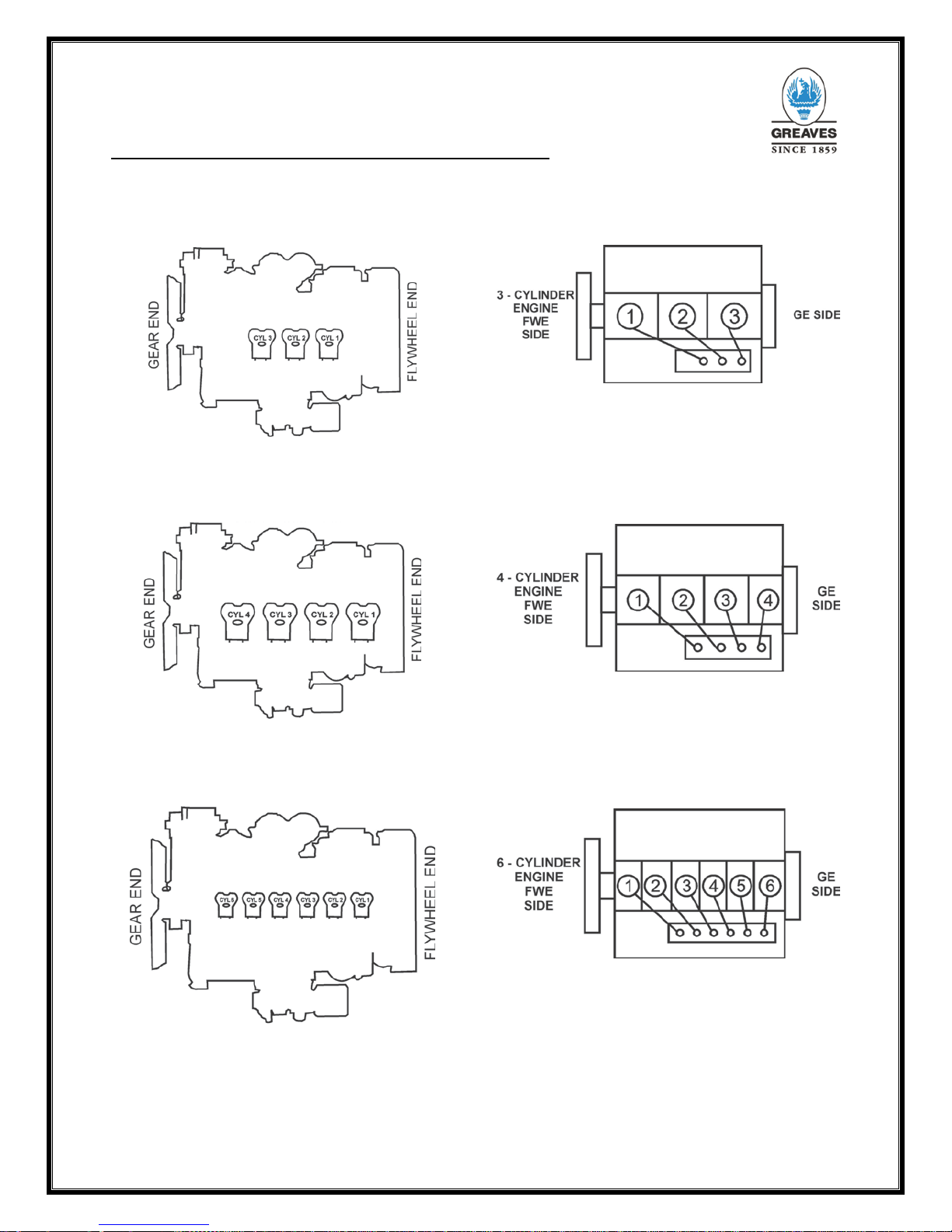
2.1 Engine Orientation of 3G
11 Series Engine
Fig. 1 Engine Orientation
2.3 Engine Orientation of 4G11 Series Engine
Fig. 5 Engine Orientation
2.5 Engine Orientation of 6G11 Series Engine
Fig.7 Engine Orientation
2.2 Cylinder Nomenclature
Fig. 4 Cylinder Nomenclature
2.4
Cylinder Nomenclature
for 4G11 engine
Fig.6 Cylinder Nomenclature
2.6 Cylinder Nomenclature for 6G11 engine
Fig. 8 Cylinder Nomenclature
2

Operational and Maintenance Manual G Series
2.7 Engine Nameplate
Fig.2 Engine Name Plate
2.8 Location of the Nameplate
Fig.3 Location of Nameplate
2.9 Engine nomenclature system
Fig. 9 Engine nomenclature
Example –
4G11TAG1 : Four cylinder turbocharged COP rating
4G11TAG2 : Four cylinder turbocharged COP rating
4G11TAG3 : Four cylinder turbocharged COP rating
4G11 TP : Four cylinder turbocharged PRP rating
4G11 NA : Four cylinders COP rating naturally
aspirated 4G11Tx -
x-Represents model G1 – 4G11T , G2 – 4G11T
3
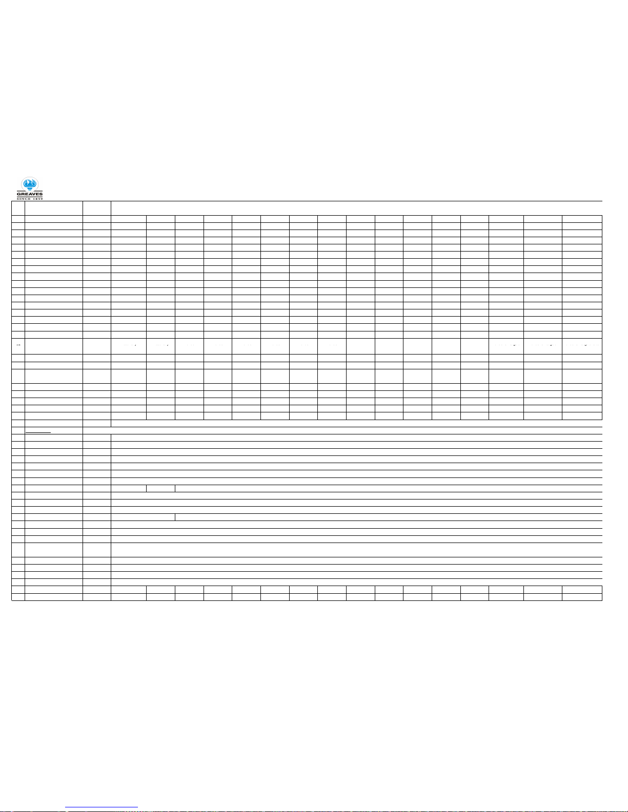
Sr.No Parameter Unit
1
Engine Model - 3G11NAG1 3G11NAG2 3G11TG4 3G11TG1 3G11TG2 3G11TG3 4G11TG1 4G11TG2 4G11TAG1 4G11TW1 4G11TAG2 4G11TAG3 6G11TAG1 6G11TAG2 6G11TAG3 6G11TAG4
2
Genset kVA Rating Prime - 25 30 35 40 45 50 62.5 75 82.5 82.5 100 125 14 0 160 180 200
3
Alternator efficiency (%) 86.9 88.9 88 .35 88.7 89 88.5 9 0.85 90.9 90.5 90.5 90.6 92.5 92.3 92.5 92.9 93.1
4
kWe 20 24 28 32 36 40 50 60 66 66 80 1 00 11 2 128 14 4 160
5
kWm rated net 23.01 27.00 31.69 36 .08 40.45 45.20 55.0 66.0 72.9 72.9 88.3 108.1 121.3 138.4 155.0 171.9
6
kWm rated gross 2
4
.3 28.0
33.1 38.2 43.4 47
61.0 69.1 77.2 77.2 93.4 114.0 127.2 144.5 163.0 178.8
7
Rated speed RPM 1500 1500 1 500 1500 1500 1500 1500 1500 1500 1500 1500 1500 1500 1 500 1500 1500
8
Bore X Stroke mm 1
05x130 105x130 105x130 105x130 105x130 105x130 105x130 105x130 105x130 105x130 105x130 105x130 105x130 105x130 105x130 10 5x130
9
Engine Configuration - Inline Inline Inline Inline Inline Inline Inline Inline Inline Inline Inline Inline Inline Inline Inline Inline
10
Working principle - 4 -Stroke 4-Stroke 4-Stroke 4-Stroke 4-Stroke 4-Stroke 4-Stroke 4-Stroke 4-Stroke 4-Stroke 4-Stroke 4-Stroke 4-St roke 4-Stroke 4-Stroke 4-Stroke
11
No. of cylinders - 3 3 3 3 3 3 4 4 4 4 4 4 4 6 6 6
12
Total swept Volume Ltr 3.375 3.375 3.375 3.375 3.375 3.375 4.5 4.5 4.5 4.5 4.5 4.5 6 .75 6.75 6.75 6.75
13
BMEP (At rated Power) Bar 5.76 6.64 5.88 6.79 7.71 8.35 10.84 1 2.28 13.72 13.72 16.60 20.26 15.07 17.1 19. 3 21.19
14
Combustion type: DI / IDI - DI DI DI DI DI DI DI DI DI DI DI DI DI DI DI DI
15
Cooling - Water Cooled Water Cooled Water Cooled Water Cooled Water Cooled Water Cooled Water Cooled Water Cooled Water Cooled Water Cooled Water Cooled Water Cooled Water Cooled Water Cooled Water Cooled Water Cooled
16
Compression ratio - 18 18 16.2 16.2 16.2 16.2 16.2 16.2 16.2 16.2 16.2 16.2 16.2 16.2 16.2 16.2
17
No. of valves / cyl. - 2 2 2 2 2 2 2 2 2 2 2 2 2 2 2 2
Turbo
Turbo
Turbo
Turbo
Turbo
2.10 Engine Technical Specification - Genset Application 50Hz ( CPCB Stage I)
Details
18
Aspiration
-
Naturally
Aspirated
Naturally
Aspirated
Turbo
Charged
Turbo
Charged
Turbo
Charged
Turbo
Charged
Turbo
Charged
Turbo
Charged
Charged after
cooled
Charged after
cooled
Charged after
cooled
Charged after
cooled
Charged after
cooled
Turbo Charged
after cooled
Turbo Charged
after cooled
Turbo Charged after
cooled
19
Governing type - Mechanical Mechanical Mechanica l Mechanical Mechanical Mechanical Mechanical Mechanical Mechanical Mechanical Mechanical Mechanical Mechanical Mechanical Mechanical Mechan ical
20
Governing - A1 A1 A1 A1 A1 A1 A1 A1 A1 A1 A1 A1 A1 A1 A1 A1
21
Direction of rotation (From
flywheel side)
- Anti clockwise Anti clockwise Anti clockwise Anti clockwise Anti clockwise Anti clockwise Anti clockwise Anti clockwise Anti clockwise Anti clockwise Anti clockwise An ti clockwise A nti clockwise Anti clockwise Anti clockwise Anti clockwise
22
SFC at rated power * gm/kW.h 230 230 225 22 5 225 223 217 217 208 208 206 199.8 202 202 202 202
23
SFC at 75 % power * gm/kW.h 221 221 231 231 23 1 22 2 220 220 208 208 204 196.6 200 200 200 200
24
SFC at 50 % power * gm/kW.h 235 235 235 235 23 5 23 0 231 231 220 220 211 199.1 206 206 206 206
25
Weight (Dry) kg 380 380 390 390 39 0 39 0 465 465 485 485 485 485 650 650 650 650
26
Flywheel housing/Flywheel - SAE 3/11.5" SAE 3/11.5" SAE 3/11.5" SAE 3/11.5" SAE 3/11.5" SAE 3/11.5" SAE 3/11.5 " SAE 3/11 .5" SAE 3 /11.5" SAE 3/11.5" SAE 3/11.5" SAE 3/11.5" SAE 1/1 4" SAE 1/14" SAE 1/14" SAE 1/14"
27
Emission compliance -
Components
28
FIP type -
29
Injector -
30
Water pump -
31
Lub oil pump -
32
Cylinder head -
33
Crank shaft -
34
Fan drive -
35
Lub oil cooler - NA N
A
36
Air Cleaner -
37
Engine Starting System -
38
Lub oil filter -
Centrifugal - Gear driven
G rotor - Gear driven
Unit cylinder head
Forged - induction hardened
Independent fan drive arrangemen t Vee belt
P type
Mechanical
Compliant to CPCB Stage I, Upgradable to CPCB Sta ge II
Plate type water cooled
Dry Type
12/24V DC
Single element - spin on type
39
Fuel filter -
Fuel circuit
40
Fuel to be used -
41
Fuel filteration micron
42
Max suction lift by feed
pump
meter
43
Fuel feed pump pressure Bar
44
Nozzle opening pressure Bar
Lub oil circuit -
45
Lub oil grade -
46
Lub oil sump capacity Ltrs 6 6 8 8 8 8 10 10 10 10 10 10 17 17 17 17
47
Lub oil change period Hrs 500 hrs
IS-1460 2005 cetane 51 S 0.01 5% Density 0.825
Twin element- coarse + fineSingle element
GREAVES MAXTHERM APICF4 15W40
10
1
1.5
250 +/-10
4
As per IS:1462 2005 with 5% tolerance & SFC fig. are for a well-run in Engine
Operational and Maintenance Manual G11 Series
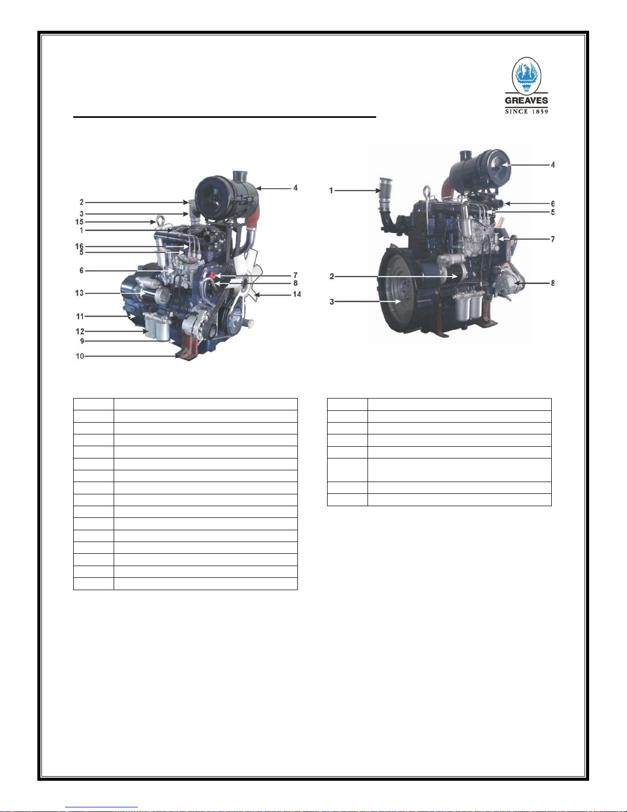
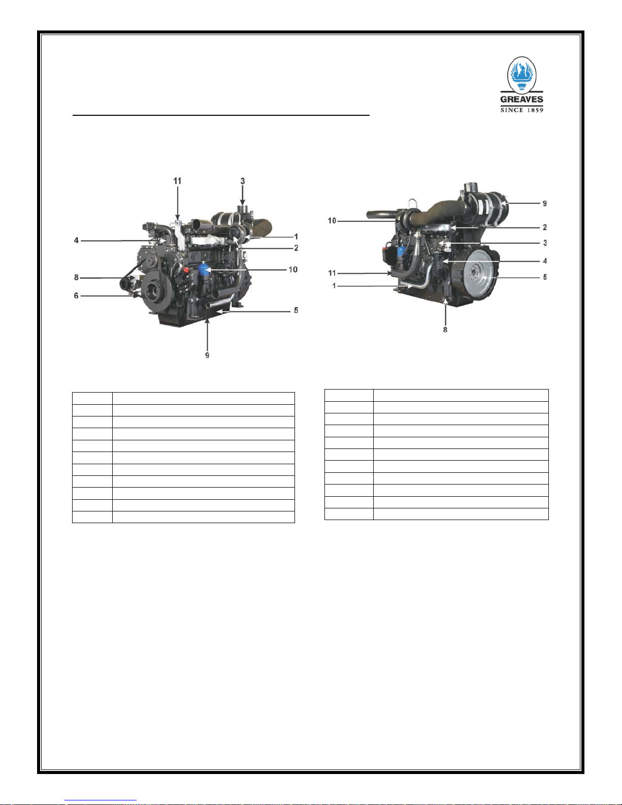
2.11 Engine Illustrations for 3G11 Series
Engine
Fig. 10 3G11 Series engine
1. Rocker cover
2. Exhaust out
3. Exhaust bellow
4. Air filter
5. Cylinder head
6. Fuel pump
7. Oil filler cap
8. Blow by pipe
9. Oil sump
10. Engine foot
11. Flywheel housing
12. Fuel filter
13. Starter
14. Fan
15. Lifting hook
16. F uel pipe
Fig. 11 3G11 Series engine
1. Exhaust bellow
2. Starter
3. Engine flywheel
4. Air cleaner
5. High pressure fuel line
6. Water outlet to Radiator/
Heat Exchanger
7. Feed pump
8. Alternator
5
Operational and Maintenance Manual G11 Series
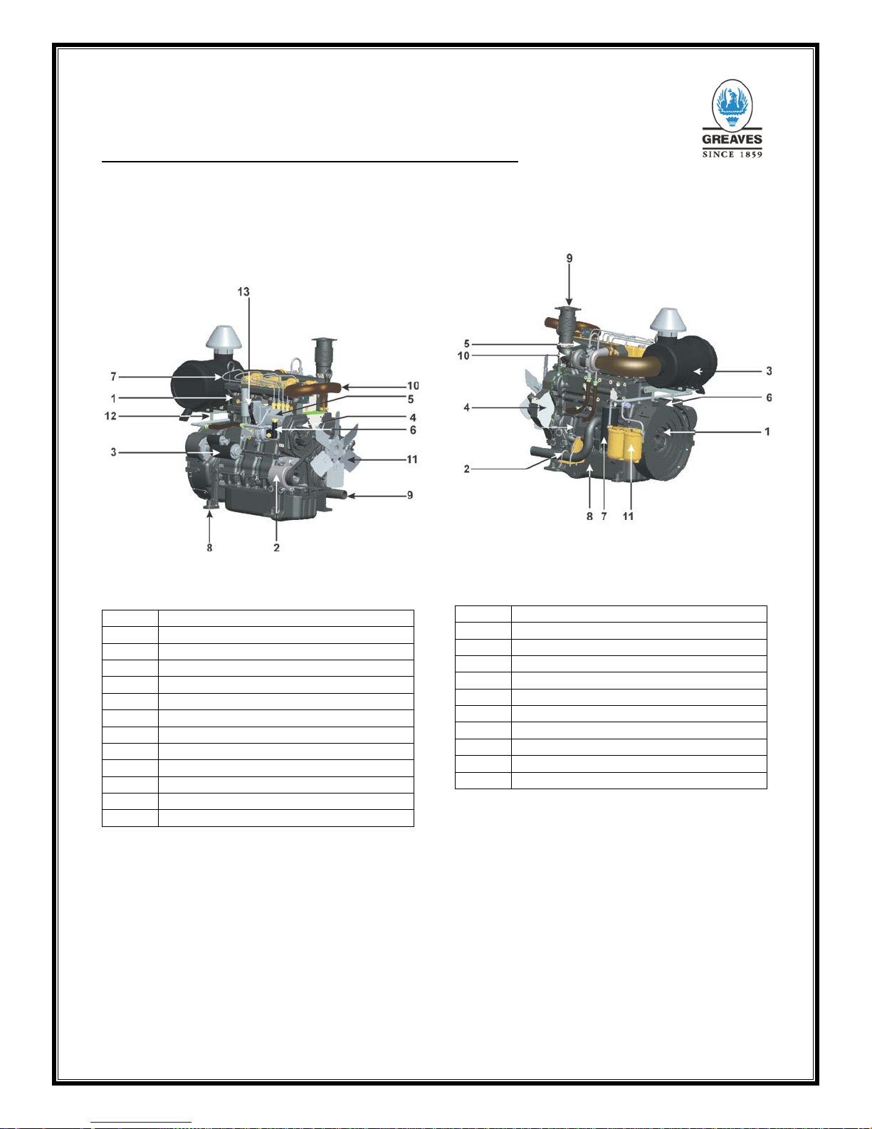
2.12 Engine Illustrations for 4G11 Series
Engine
F
ig. 12 4G11 Series engine
1. Cylinder head
2. Battery charging alternator
3. Starter
4. Oil filler cap
5. Fuel pump
6. Fuel feed pump
7. High pressure pipe
8. Engine foot
9. Water in
10. Water out
11. Fan
12. Air filter bracket
13. Stop lever
F
ig. 13 4G11 Series engine
1.
Flywheel
2.
U clamp
3.
Air filter
4.
Gear end casing
5.
Air intake manifold
6.
Flywheel housing
7.
Lub. oil filter
8.
Oil sump
9.
Exhaust out let
10.
Exhaust bend
11.
Fuel Filter
6

Operational and Maintenance Manual G11 Series
Notes
7
Operational and Maintenance Manual G11 Series
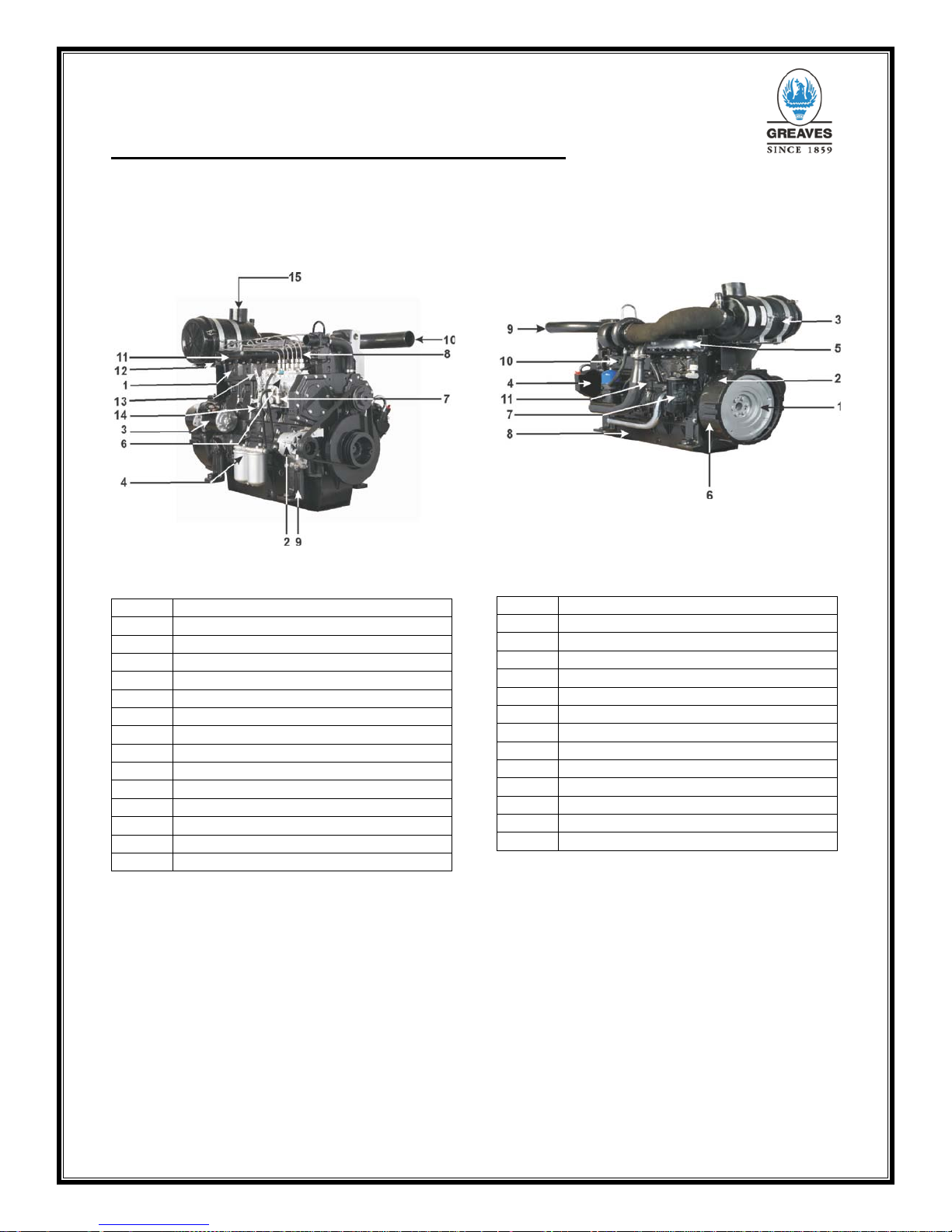
2.13 Engine Illustrations for 6G11 Series
Engine
Fig. 16 6G11 Series engine
1.
Cylinder head
2.
Battery charging alternator
3.
Starter
4.
Fuel filter
5.
Oil filler cap
6.
Fuel pump
7.
Fuel feed pump
8
High pressure pipe
9.
Engine foot
10.
Water out
11
Water inlet manifold
12.
Air filter bracket
13
Stop lever
14.
Throttle lever
15.
Air inlet pipe
Fig. 17 6G11 Series engine
1. Flywheel
2. Sensor
3. U clamp
4. Air filter
5. Gear end casing
6. Air intake manifold
7. Flywheel housing
8. Lub. oil filter
9. Oil sump
10. Exhaust out let
11. Exhaust manifold
12. Exhaust bend
13. Crank case
14. Radiator Hose
8
Operational and Maintenance Manual G11 Series
2.13.1 Engine Illustrations for 6G11 Series
Engine
Fig.18 6G11 Series engine
1. Turbocharger
2. Exhaust out
3. Air inlet
4. Cylinder head
5. Oil sump
6. Belts
7. Breather
8. Alternator
9. Oil drain plug
10. Centrifugal Filter
11. Lifting bracket
Fig.19 6G11 Series engine
1. Water Inlet
2.
Water manifold
3.
Exhaust manifold
4. Lub. Oil filter
5.
Flywheel
6.
Flywheel housing
7. Oil header
8.
Engine foot
9.
Air Cleaner
10. Turbo charger
11.
Exhaust outlet
9
Operational and Maintenance Manual G11 Series
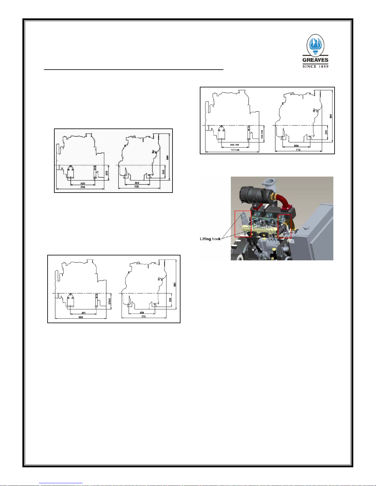
2.14 Dimensions and weight – 3G11 Series
Engine
For overall dimensions see the layout drawing.
Engine weight - 380 kg
Flywheel flange – SAE 3/11.5
Fig. 20 Overall Engine Dimensions
2.1
5 Dimensions and weight – 4G11 Series
Engine
For overall dimensions see the layout drawing.
Engine weight - 465 kg
Flywheel flange – SAE 3/11.5
Fig. 21 Overall Engine Dimensions
2.16 Dimensions and weight – 6G11NA
For overall dimensions see the layout drawing.
Engine weight – 650 kg
Flywheel flange – SAE1/14”
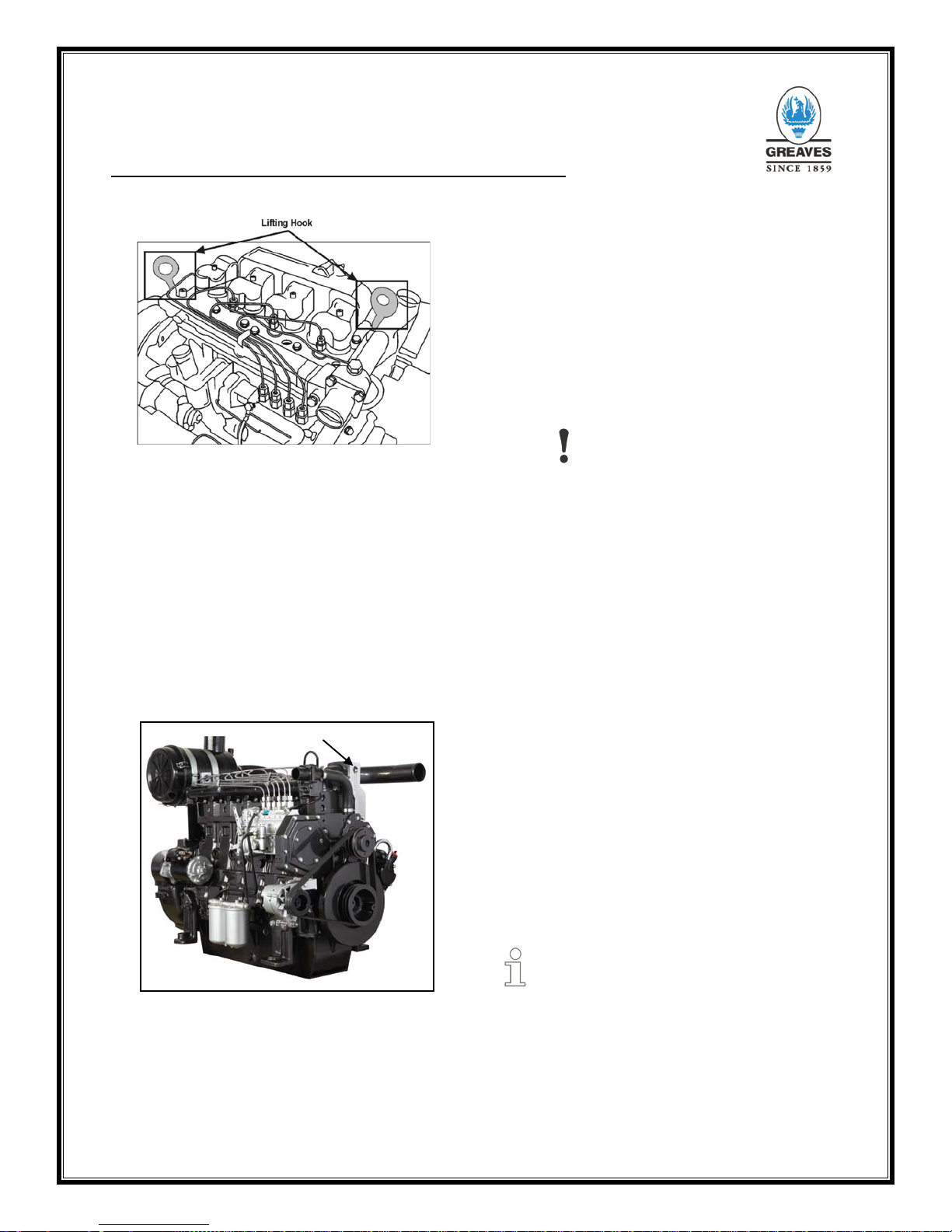
2.17 Engine Lifting Instructions
Fig. 22 Lifting Hook for 3G11 Engine
Take all safety precautions while lifting and
moving the engine. Only trained personnel should
handle the engine. You can consult Greaves
service dealers, if necessary.
Remove water and oil from the engine before
lifting. If your engine has cast iron sump then th e
engine can be rested on t he sump. For an y other
type sump, use blocks under engine feet.
Avoid jerks or abrupt resting of engine. The
engine should never be rested, stored or lift ed in
any other direction than upright. The engine
should never be rolled on the ground.
10
Operational and Maintenance Manual G11 Series
Fig. 23 Lifting Hook for 4G11 Engine
The engine is provided with four transportation
feet even if only two feet (gear end) are required
for application. Store the spare feet, (flywheel
end) carefully. Fit those two extra feet before
lifting the engine. The engine should not be
rested on bell housing for long durations.
Use only the eyebolts provided on the engine
crankcase for lifting purpose. The eyebolts are to
be used for lifting engin e only. Do not lift engine
coupled with alternator or entire DG set using
these bolts. Ensure that, the
I bolts are
completely engaged before engine is lifted.
Fig. 24 Lifting Hook for 6G Engine
While lifting the engine, use
correct size of
tackles, ropes, chains, cranes, hoists or any other
lifting or transportation device. While lifting or
transportation, the ropes or tackles should be
positioned in such a wa y that the y do not dam age
engine components lik e rock er cover, fuel pumps,
high pressure pipes, etc. The engine should be
balanced while lifting and moving. Do not keep
the engine hanging on lifting tackles .
2.18 T
ransport, packing and storage
2.18.1 Safety notes for transport
CAUTION!
Damage due to improper transport!
Significant damage to property and injuries to
persons can occur in the case of improper
transport.
Therefore:
• Proceed carefully when unloading the
packages and on delivery and internal
transport and observe the signs and
notices on the packing.
• Only use the attachment points provided.
• Do not remove pack ing unt il j us t bef ore t he
installation.
2.18.2 Transport inspection
Check the delivery immediately on receipt for
completeness and transport damage.
If externally detectabl e transport damage is found,
proceed as follows:
• Do not accept the delivery, or only with
reservation.
• Record the extent of transport damage in
the transport documents or on the deliver y
note of the forwarding agent.
• Start complaints procedure.
NOTE!
• Claim any damage as soon as it is
detected.
• Compensation claims can only be
submitted within
• The applicable complaints periods.
11
Operational and Maintenance Manual G11 Series
3. SYSTEMS
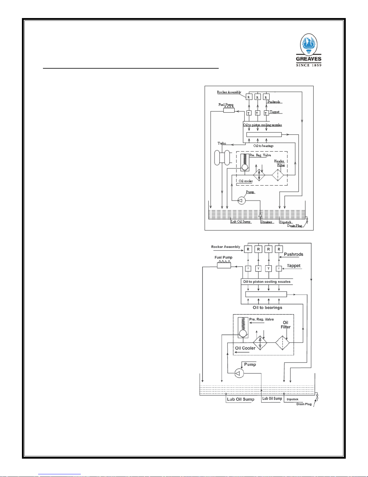
3.1 Lubrication System
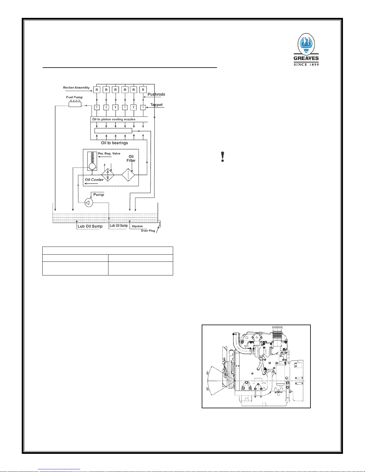
3.1.1 G11 Engine Lub. System
G11 series engines use positive pressurized
lubrication system. The main functions of the
lubrication system are as follows:
• Lubrication of friction related parts.
• To carry away the heat generated by
friction
• To avoid corrosion
• To wash away debris created by friction
wear.
a) The G11 series engine uses a positive
displacement, G-rotor pump, which is gear
driven.
b) The system has a pressure-regulating
valve, lube oil filter and lube oil cooler,
which are housed in a lube oil header.
c) Providing oil through push rod lubricates
the rocker assembly. The fuel pump and
turbo chargers are positively lubricated.
The lube oil system is adequately designed to
provide sufficient lubrication, oil change period,
filter element life and minimize lube oil
consumption and running cost.
Fig. 25 Lubrication System of 3G11 Series Engine
F
ig. 26 Lubrication System of 4G11 Series Engine
12

Operational and Maintenance Manual G11 Series
Fig. 27 Lubrication System of 6G11 Series Engine
Recommended Oil for G series engines
Company Oil brand name
Greaves Cotton Ltd
Greaves Maxtherm
(API CF -4- 15 W 40)
Engine Oil Recommendations for Greaves
Engines
Quality of Lubricating oil is one of the key drive
factors to decide the performance, Durability and
total cost of operation of di esel engine. Hence we
have always been recommending the best
available / suitable engine oil to be used in our
engine. Greaves Ferymann has been continuously
upgrading the products to incorporate latest
technology such as low temperature after cooling ,
two stage turbo charging, electronics, air to air
charge air cooling, high p ower to weight ratio etc.
for meeting customer expectations of engine
performance, durability and cost of operation.
Lubricating oil has also undergone various
improvements to meet the requirements of these
changes in diesel engine technology. With this,
SAE 15W40 grade Lubricating oil with API CH-4
classification is now available in India from m ost of
oil companies. T his is the best e ngine oil current ly
available in India suitable for Greaves engines.
Greaves India Limited strongly recommends the
use of SAE 15W40 Lub oil with API CH-4, CES
20071 & CES 20076 clas sification for all Greaves
engines to get the various advantages and
optimum performance from the engine. This oil has
a minimum TBN of 10.5 to counteract the higher
sulphur content of high speed diesel available in
India.
CAUTION
Beware of the spur ious oils in the market. Bad oil
quality is detrimental to engine performance.
Hence oil should always be procured from the
original manufactur er or the authorized distributor .
Lubricating oil to be used i n the engine must meet
all qualities as per manufacturer’s specifications.
Greaves India recomm ends audit checks of fresh
engine oil to ensure the quality of oil. Facility to
check suitability of oil for us ing it in the engine is
available with Greav es service network.If in doubt
about the quality of lub oil, contact lub oil
manufacturing com pany / Greaves ser vice net work
and get oil analysed in laboratories. Do not
intermix different brands of oil as two different
brands of oils may not be compatible with each
other. It is therefore recomm ended that the brand
which is used for initial fil l / oil change, s hould only
be used for top-up. Different brand of oil may be
used after draining all the existing oil i.e., at the oi l
drain interval and after f lushing the lub oil system
with new brand of oil.
3.1.2 Permissible engine inclination
Fig.28 Engine inclination
13
Operational and Maintenance Manual G11 Series
Fig. 27 Lubrication System of 6G11 Series Engine
Recommended Oil for G series engines
Company Oil brand name
Greaves Cotton Ltd
Greaves Maxtherm
(API CF -4- 15 W 40)
Engine Oil Recommendations for Greaves
Engines
Quality of Lubricating oil is one of the key drive
factors to decide the performance, Durability and
total cost of operation of di esel engine. Hence we
have always been recommending the best
available / suitable engine oil to be used in our
engine. Greaves Ferymann has been continuously
upgrading the products to incorporate latest
technology such as low temperature after cooling ,
two stage turbo charging, electronics, air to air
charge air cooling, high p ower to weight ratio etc.
for meeting customer expectations of engine
performance, durability and cost of operation.
Lubricating oil has also undergone various
improvements to meet the requirements of these
changes in diesel engine technology. With this,
SAE 15W40 grade Lubricating oil with API CH-4
classification is now available in India from m ost of
oil companies. T his is the best e ngine oil current ly
available in India suitable for Greaves engines.
Greaves India Limited strongly recommends the
use of SAE 15W40 Lub oil with API CH-4, CES
20071 & CES 20076 clas sification for all Greaves
engines to get the various advantages and
optimum performance from the engine. This oil has
a minimum TBN of 10.5 to counteract the higher
sulphur content of high speed diesel available in
India.
CAUTION
Beware of the spur ious oils in the market. Bad oil
quality is detrimental to engine performance.
Hence oil should always be procured from the
original manufactur er or the authorized distributor .
Lubricating oil to be used i n the engine must meet
all qualities as per manufacturer’s specifications.
Greaves India recomm ends audit checks of fresh
engine oil to ensure the quality of oil. Facility to
check suitability of oil for us ing it in the engine is
available with Greav es service network.If in doubt
about the quality of lub oil, contact lub oil
manufacturing com pany / Greaves ser vice net work
and get oil analysed in laboratories. Do not
intermix different brands of oil as two different
brands of oils may not be compatible with each
other. It is therefore recomm ended that the brand
which is used for initial fil l / oil change, s hould only
be used for top-up. Different brand of oil may be
used after draining all the existing oil i.e., at the oi l
drain interval and after f lushing the lub oil system
with new brand of oil.
3.1.2 Permissible engine inclination
Fig.28 Engine inclination
14
Operational and Maintenance Manual G11 Series
3.2 Engine Cooling Systems
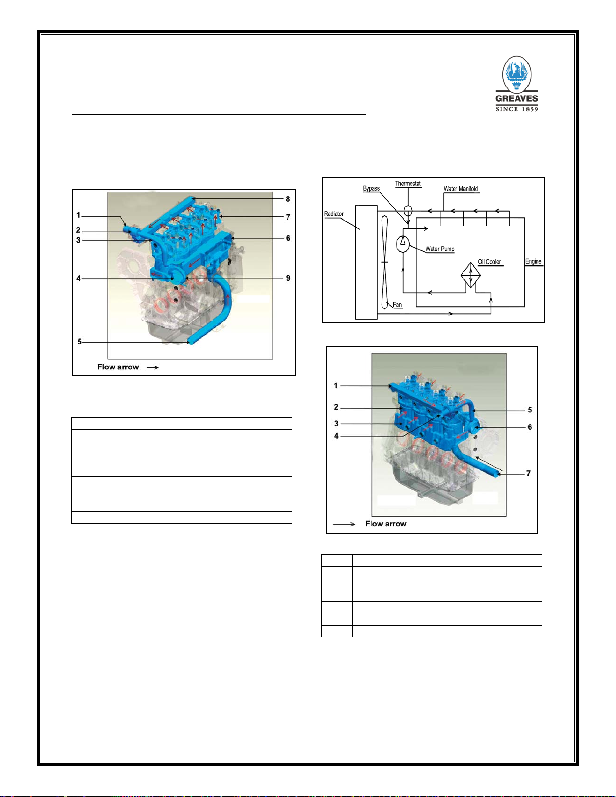
3.2.1 G11 Series Engine Cooling System
Fig. 29 3G11 series engine cooling system
1.
Water out to radiator
2.
Thermostat
3.
Bypass
4.
Water pump
5.
Water in from radiator
6.
Oil cooler cavity
7.
Cylinder head
8.
Water manifold
9.
Weeping hole
G11 series engines are water-coole d engines. T he
water pump is gear driven. The water is cooled b y
a radiator fan system. The fan is driven by a fan
drive system and is not mounted on the water
pump. The water also co ols lube oil in the lube oil
cooler.
A thermostat (74ºC s tar t to 82ºC f ull op en) con trols
the water temperature. The radiator has a pressure
cap, which maintains the st atic pressure at 0.5 bar
(7 psi). A drain plug is provided to drain the
system. The water system provides adequate
cooling in a sim ple and efficient manner to satis fy
the cooling needs of canopy enclosed genset
application.
Fig.30 Cooling System diagram for G11 Series Engines
Fig.31 4G11 S
eries Cooling System
1. Water outlet manifold
2. Cylinder water cavity
3. Water core
4. Water out
5. Bypass
6. Water pump
7. Water in
15
Operational and Maintenance Manual G11 Series
3.2.2 Cooling system data
Pump Centrifugal
Drive
Engine driven gear drive
Static water
pressure
(radiator cap)
7 psi
Typical steady state
water temp
72 – 90°C
Max allowable water
temp
95 - 96°C
3
.2.3 Water specifications
pH value 6 – 8
Calcium/magnesium
hardness
180-ppm max
Chlorides Less than 40 ppm
Sulfates
Less than 100 ppm
TDS (Total
Dissolved Solids)
Less than 400 ppm
3.
2.4 Coolant additive specification
Fill requisite quantity of cooling water duly mixed
with Greaves maxtherm specialty summer coolant /
anti-freeze compounds about 20% by volume or
cooling conditioner with anti-freeze, if required.
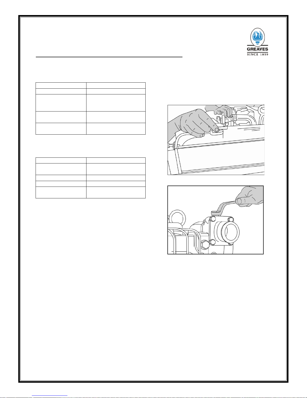
3.2.5 Filling up coolant on a new installation
The engine is supplied with the coolant, which has
to be filled up after installation. For this refer
procedure below:
1. Open the de-aeration plug.
2. Open the radiator cap.
3. Ensure all hoses are in place.
4. Prepare coolant in the specified proportion.
5. Pour coolant through the spout.
6. Water takes some time to fill up the system
through the radiator tubes.
7. Wait for 20 seconds before restarting the
pouring.
8. Coolant will first start coming out of the
de-aeration opening.
9. Wait for the air to escape and close the
plug.
10. Keep on pour ing till t he water is filled up in
the radiator top tank. Close the cap firmly.
Fig. 32 Radiator Cap
Fig. 3
3 De-aeration Plug
3.2.6 Topping up coolant in an already installed
engine
1. Never ope n the radiator cap of an engine
that has just stopped.
2. W ait for at least 15 minutes after stopping
the engine.
3. For norm al top ups, it is not necessary to
de-aerate the system.
4. Fill up coolant wait till the coolant level
settles.
5. Confirm that the level is correct. Put the
radiator cap back.
16
 Loading...