

GREAT WATER QL Series Operator's Maintenance Manual
QL Thruster Series
Operator’s & Maintenance manual
QL Thruster Series
QL Strahlruder-Serie
Betriebsanleitung und Wartungshandbuch
Gamme de propulseurs QL
Manuel d’utilisation et d’entretien
Hé lice de maniobra Series QL
Libro de instrucciones y Manual de
mantenimiento
QL Serie elica di manovra
Manuiale di Uso e Manutenzione
QL Bogpropellrar
Instruktions- och underhå llshandbok
14 Arsene Way, Fairhaven, MA 02719
774-328-9498 Toll free 866-209-6132
Info@great-water.com


English ........................................................................ 4 - 11
Deutsch ..................................................................... 12 - 19
Franç ais ..................................................................... 20 - 27
Españ ol ...................................................................... 28 - 35
Italiano ...................................................................... 36 - 43
Svenska ...................................................................... 44 - 51
English
4
This symbol is used in this manual and on the
product, to call your attention to the fact that
this is safety information. Always read such information very carefully.
Safety texts in the manual have the following order of
priority:
Warning!
Warns for the risk of personal injury, major damage to product or property, or serious malfunctions if the instruction is ignored.
Important!
Is used to call attention to things which could
cause damage or malfunctions to product or
property.
Note! Is used to call attention to important information, to facilitate work processes or operations.
Warning!
The bow thruster and control unit must not be installed in areas where inflammable or explosive
gases may become present.
Do not install thruster and control unit in close
range to easily ignitable materials.
Important!
QL Thrusters are designed for leisure craft use only.
Important!
When installed in boats approved or classified according to international or special national rules, the installer is responsible for following the demands in
accordance with these regulations / classification
rules. The instructions in this manual can not be
guaranteed to comply with all different regulations /
classification rules.

5
English
Important user precautions
Warning!
A rotating propeller can cause severe injury. Check
that there is nobody in the water before you engage
thruster(s). Never use thruster close to swimmers or
in areas where you could reasonably expect that people could be in the water.
Warning!
Do not run the thruster(s) out of the water.
Warning!
When servicing the thruster(s), always turn off the
main power switch(es).
Warning!
Never store anything (e.g. sails, ropes etc.) in the
same compartment as the thruster and control unit.
When the thruster runs for a longer period it will get
hot and may cause damage.
Important!
The thruster must only be operated by persons with
knowledge of the system.
Important!
Always turn the thruster(s) main power switch(es)
off when the system is not in use and when leaving
the boat.
English
6
QL Touch panel, Joystick and
Rocker switch
How to use a bowthruster
Note! Please take some time to practice thruster usage in
open water to become familiar with thruster operation
and to avoid damage to your boat.
Important!
Keep main engine(s) running when operating
thruster(s) to ensure enough electrical power.
1.
Turn the main power switch for the thruster on.
2.
Press the On/Off switch to engage the thruster (LED will
glow on the Joystick control panel). This is not applicable
on QL Touch panel.
3.
Push button or move Joystick / Rocker switch to left, boat
moves to port (left). Push button or move Joystick /
Rocker switch to right, boat moves to starboard (right).
For more detailed information; see the examples of manoeuvering on the last pages of this manual.
Important!
The system is equipped with an automatic safety
shut off function to avoid overheating.
The maximum continuous running time is 30 seconds.
When the thruster is used for an accumulated time
of 2 minutes or 4 times 30 seconds, the safety system require the thruster to cool down for a period of
25 minutes.
Important!
There is a 1.5 second delay when changing directions. This is for allowing the motor and water column to slow down.
Important!
Always turn the thruster(s) main power switch(es)
off when the system is not in use and when leaving
the boat.
How to use a bow & stern thruster
The combination of a bow and stern thruster offers sideto-side manouverability to the boat and the opportunity
to move the bow and the stern separately of each other.
For more detailed information; see the examples of manoeuvering on the last pages of this manual.
Important!
When using thruster(s) take into consideration the
inertia effects, i.e. the boat will continue to move after you release the button / Joystick / Rocker switch,
therefore remember to release the button / Joystick /
Rocker switch shortly before reaching your desired
position.
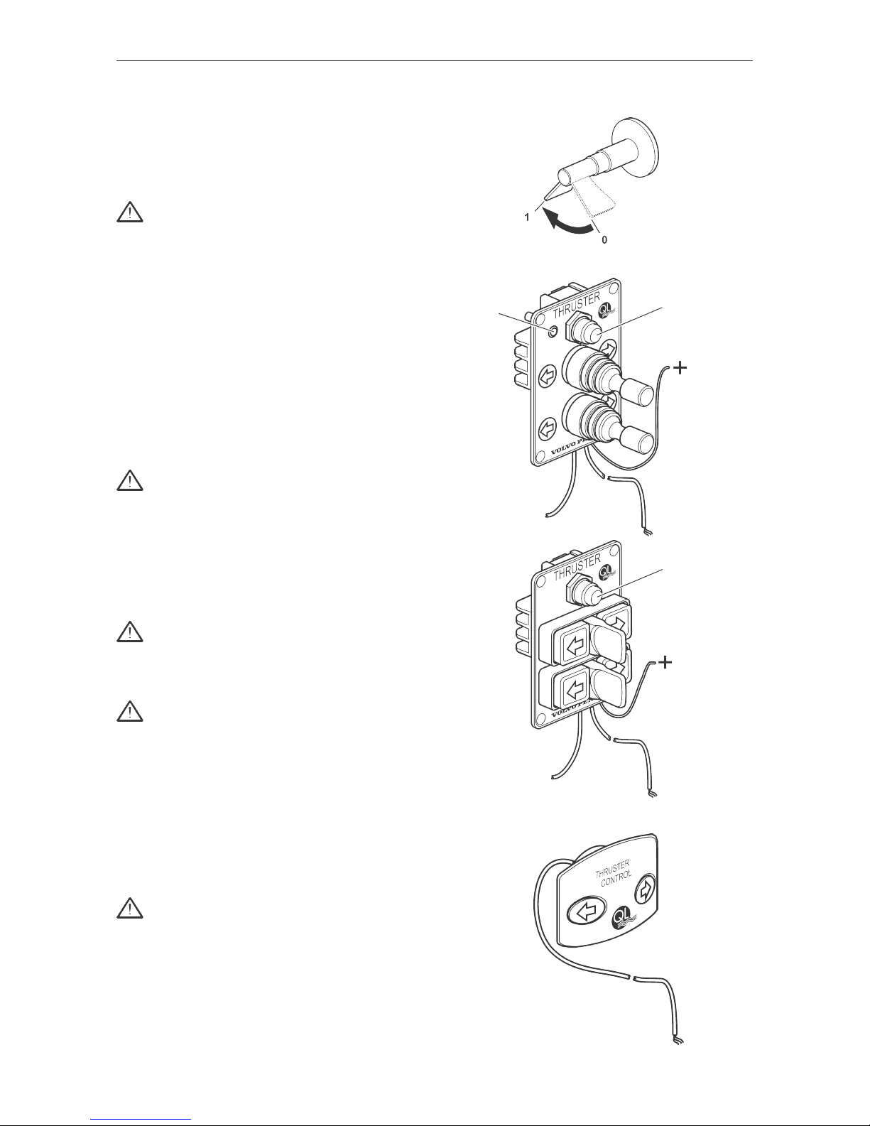
Fig. 1
On/Off
LED
On/Off
QL Rockerswitch
QL Joystick
QL Touch panel
Fig. 2
Fig. 3
Fig. 4
7
English
Test running
Warning!
Make sure no one is within reach of the rotating propeller and that no objects are in the tunnel before
testing. Do not operate the thruster without the belt
cover installed.
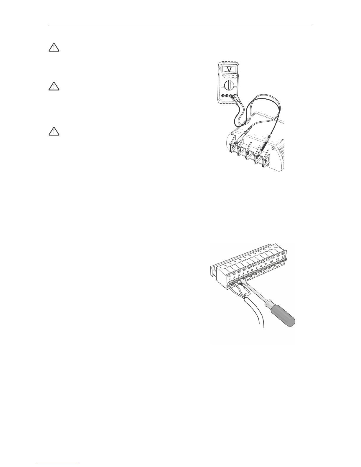
Important!
Make sure that the battery is properly charged before testing. Voltage, measured at the control unit
(Batt. + and Batt. - / A1, see fig. 5) during operation,
below 10.5 V / 21 V will cause damage to the main
relay.
Warning!
Do not run the thruster(s) out of water.
When the boat is launched:
• Turn the Joystick / Rocker switch to left / push left
arrow button, and the boat moves to port. Turn
Joystick / Rocker switch to right/push the right arrow
button, and the boat moves to starboard. If not,
continue to section “ Reversing direction” .
Note! All power consuming equipment should always be
run with care. The engine(s) or the on-board generator
that replenish the batteries must always be running when
the thruster is used to keep the generators charging the
thruster batteries.
Reversing direction
Touch panel, Joystick, Rockerswitch
If the operating direction when using Touch panel, Joystick or Rocker switch is wrong, follow this procedure.
1.
Turn off the main power switch(es).
2.
Switch the wires connected to no. 1 and no. 3 on the control unit (see fig. 6).
3.
Turn the main power switch(es) for the thruster(s) on and
verify in a safe and controlled manner correct operation
from all thruster control panels.
Fig. 6
Fig. 5

English
8
To ensure quality and function of the thruster, use the following checklist prior to each season or minimum once a
year.
Warning!
When servicing the thruster(s), always turn off the
main switch(es).
Mechanical check
• Check for loose bolts, covers and cable supports.
Tighten if necessary.
• Check that the propeller can rotate freely.
• Check the propeller for damages. Replace if necessary.
• After removing propellers, use new bolt / washer / nut
when installing the propeller.
• If a motor support is installed. Please make sure it is
intact.
Battery / charger check
• Check the battery for clean and tight terminals and, if
possible, correct electrolyte level.
• Use recommended battery. The battery capacity must
correspond to the QL Thruster requirements table .
• Check the charging voltage, measured on the battery.
Correct charging voltage at 20°C (68 F) is:
14.4 V on 12 V systems
28.8 V on 24 V systems.
If not, please contact your service dealer.
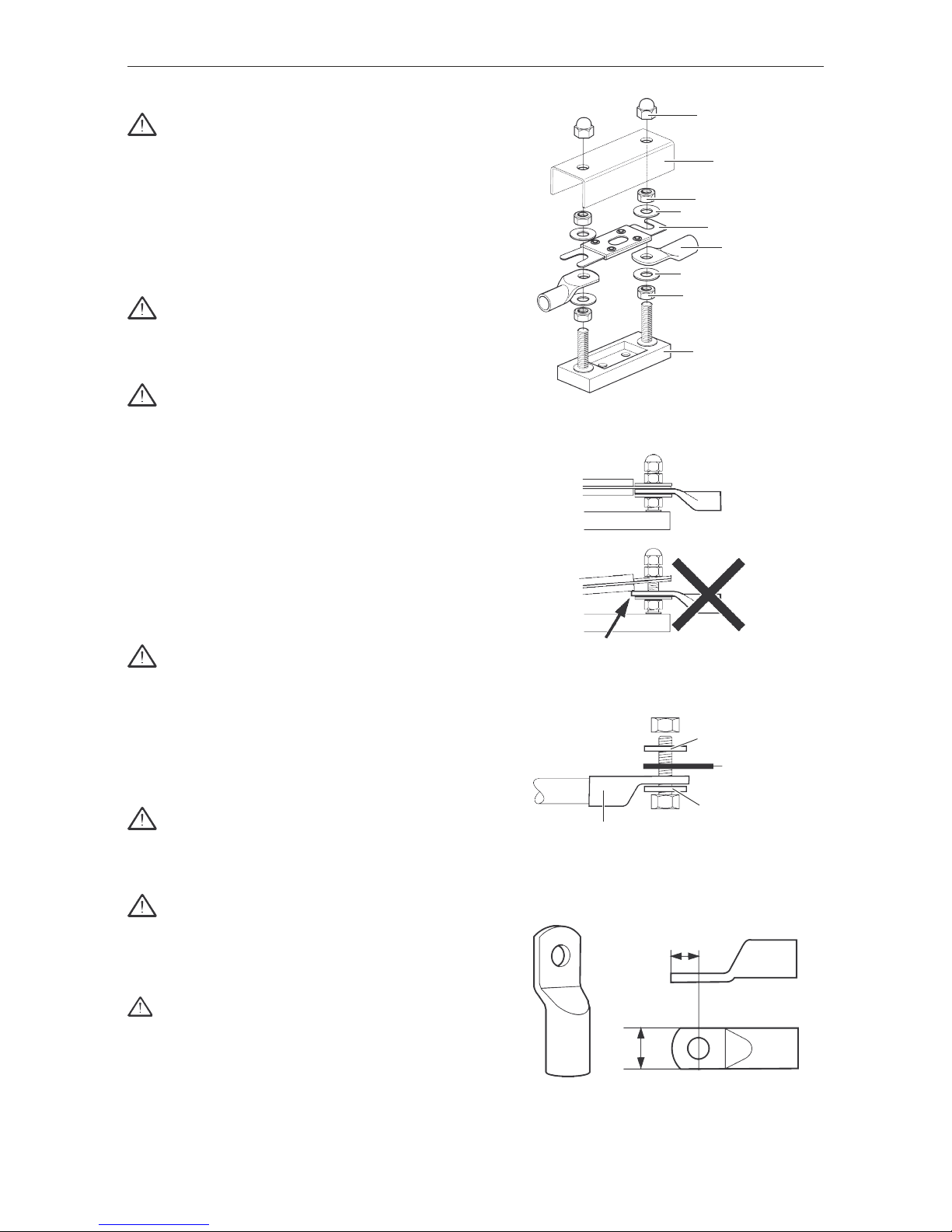
High current cable / connections check
• Check all high current components and connections,
including main switch, fuse, possible bulkhead feed
through, motor and control unit connections. Be sure
that all connections are copper to copper (or copper to
brass). Any kind of other metals / materials between,
will result in voltage drop, see fig. 7. Tighten
connections if necessary.
• Check that cable dimension and length corresponds to
the QL Thruster requirements table.
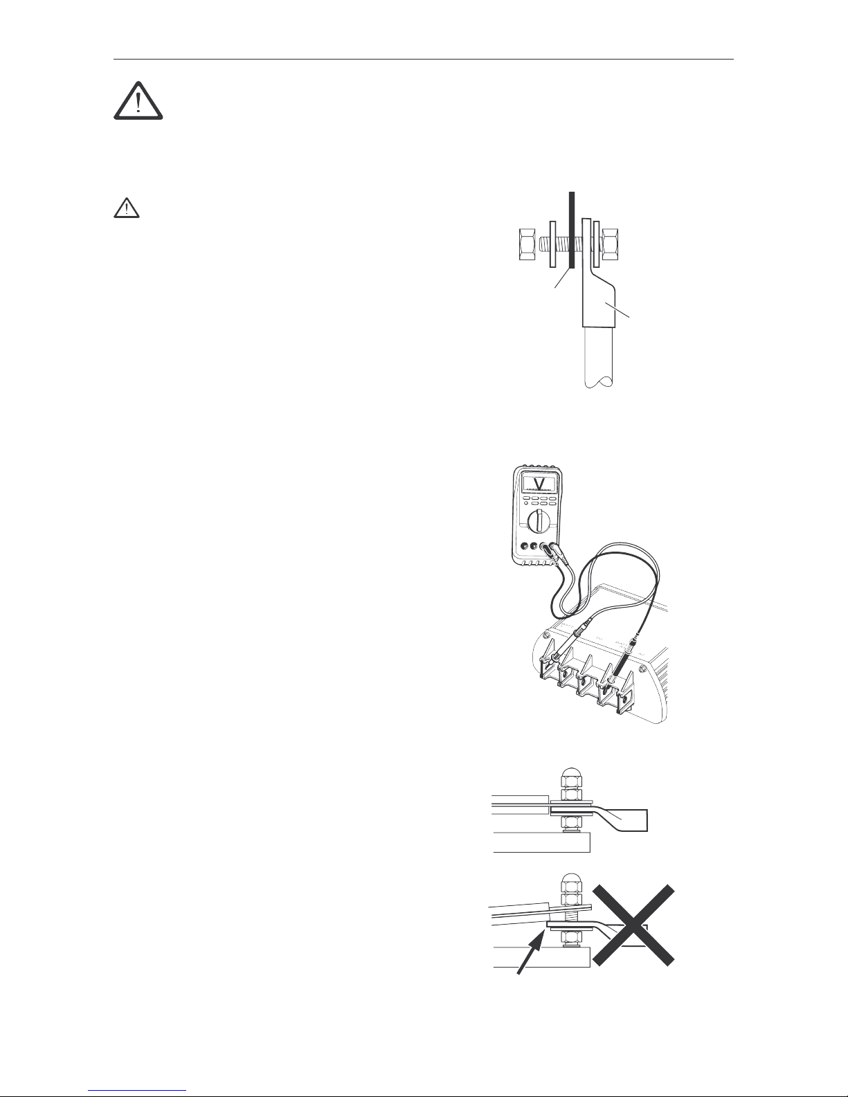
• For optimal thrust, voltage measured at the control
unit (Batt + and Batt -/A1, see fig. 8) during operation
must be more than:
10.5 V on 12 V systems
21.0 V on 24 V systems
If the voltage is allowed to go below 10.5 V / 21 V,
when the thruster is operated, it will damage the main
relay.
• Check that there is a complete contact between the
fuse and the power cable lug. See fig. 9.
Fig. 9
Important! - Maintenance guide - Thruster
Fig. 7
Fig. 8
Cable lug
Component
9
English
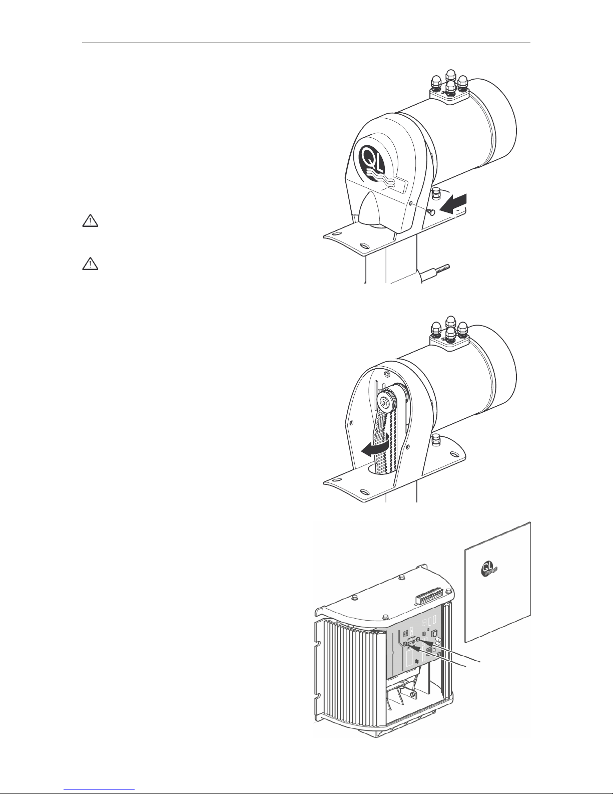
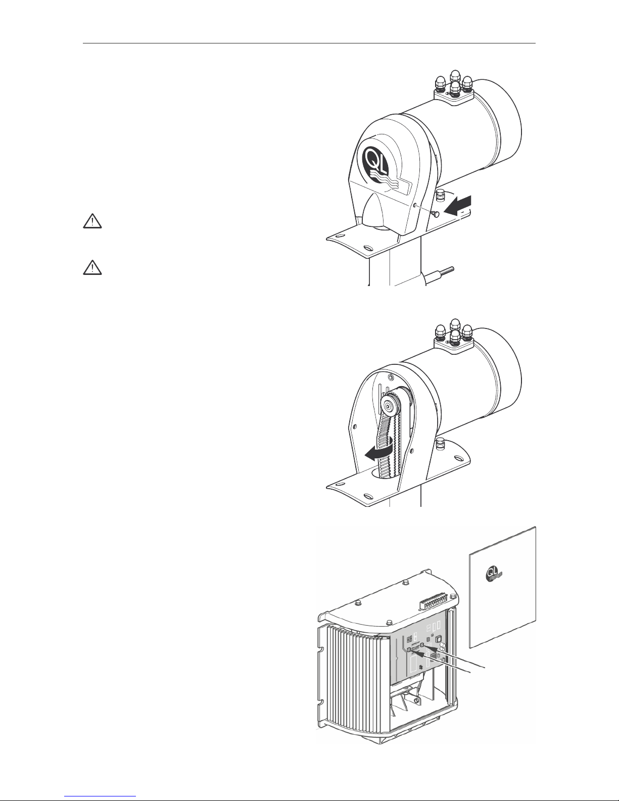
Belt drive maintenance (CT-series)
• Check the belt drive.
To inspect the belt, the beltcover must be removed (see
fig. 10, CT600).
Make sure that no teeth are damaged or worn. Correct
tension is when the belt can be twisted about 45° (see fig.
11).
If adjustment is required, loosen the flange bolts and increase or decrease the tension by adjusting the the bolt
under the motor. Tighten the flange bolts and recheck the
belt tension.
Function test - general guidance
Important!
Keep hands and loose objects away from thruster
when operating.
Important!
In general, function testing requires running in water, to achieve normal load. With no load, damage
to the motor can be the result, by over running at
too high RPM., because the motor will continue running some time after turning off the current. This
might cause induction of current and burned relay.
• If running in water not is possible, start the motor by
giving just a short impulse and be sure that the motor
has stopped completely before running the opposite
way.
• When checking the voltage on the control unit,
running in water will give the needed load to get
correct result. To check for any kind of leakage, testing
in water is required.
Joystick / Thruster control panel check
• Check Joystick / Thruster control panel function.
If malfunction, the following tests will show if the Joystick/
Thruster control panel is working and if the control unit is
working.
1.
• Check that you have thruster operation (different
directions) by short-circuiting terminal 1 and 2 or 2
and 3 on the control unit.
Note! Can also be tested via the test buttons on the circuit card. See fig. 12
2.
If you have thruster operation via the control unit / circuit
card, please check the joystick and the joystick cable for
faults.
3.
If there is no thruster operation via the control unit / circuit card, please check fuse, battery power, electric motor,
main relay and circuit card. (The power supply)
4.
If the electric motor runs and there is no thrust, please
check driving pins and propeller(s).
If the fault still remains, please contact your service dealer.
Fig. 12
Fig. 11
Fig. 10
English
10
A
B
Fig. 13
Thruster fuse & fuse holder
Important!
The fuse should be as close as possible to the battery and readability accessible.
Fuse replacement
Figure display the correct power cable connection to the
fuse holder. Make sure the fuse and cable lug are in complete contact and the lug is not contacting the fuse body.
Recommended torque: 15 Nm (11 lbf. ft)
Warning!
This is a high-amperage connection which requires
complete contact of the fuse to the cable lug to
avoid overheating of the connection. See fig. 14
Warning!
Note that the fuse shall be mounted directly above
the power cable lug without any washer in between.
See fig. 15
Dimensions
Part Length Width Height
Fuse holder 82 mm 25 mm 50 mm
Protection cover 120 mm 35 mm 35 mm
Cable lugs
Important!
Use of cable lugs exceeding the maximum dimensions may lead to interference with the fuse or the
connections at the control unit during installation.
A: Max. 13 mm (0.5")
B: Max. 29 mm (1.25")
Cables
Important!
Use cables with at least Type 2 (acc. to ABYC standard E-11) / Type A (acc. to ISO 10133) strandings.
Wiring insulation rating is 105°C (221°F) minimum.
Important!
All cables shall have suitable terminals installed.
Solderless crimp-on terminals and connectors shall
be attached with the type of crimping tool designed
for the termination used.
Warning!
Exposed shanks of terminals shall be protected
against accidental shorting by the use of insulating
barriers or sleeves.
Fig. 16
Fig. 14
Fig. 15
Cable lug
Supporting
washer
Fuse
Supporting
washer
Cable lug
Protection cover
Plastic nut
Fastening nut
Supporting washer
Supporting washer
Fastening nut
Fuse holder
Fuse

11
English
1) The distance from the thruster unit to the battery, one way, each cable.
Use of even larger cable dimensions and larger battery capacity may improve thruster performance.
2) Wiring insulation rating is 105°C (221°F) minimum.
QL Thruster requirements
Maximum Required
cable len
gth
1)
-- minimum minimum
Thruster Motor cable dimension. battery capacity Required
Length
1)
Dim.2) Ah CC
A
fuse amp.
m ft mm2 AWG (SAE)
BP300
12 V / 2 kW 1 - 10 1 - 33 70 2/0
10 - 20 33 - 67 95 3/0 50 Ah/12 V 550 200 A (P/N 41100904)
BP800
12 V / 5 kW 1 - 10 1 - 33 120 4/0
10 - 20 33 - 67 150 300MCN 300 Ah/12 V 1700 400 A (P/N 41100907)
BP800
24 V / 5 kW 1 - 10 1 - 33 95 3/0
10 - 20 33 - 67 120 4/0 150 Ah/24 V 1050 350 A (P/N 41100906)
BP1200 24 V / 7 kW 1 - 10 1 - 33 95 3/0
10 - 20 33 - 67 120 4/0 175 Ah/24 V 1150 400 A (P/N 41100907)
BP1300 24 V / 7 kW 1 - 10 1 - 33 95 3/0
10 - 20 33 - 67 120 4/0 175 Ah/24 V 1150 400 A (P/N 41100907)
CT600
12 V / 4 kW 1 - 10 1 - 33 95 3/0
10 - 20 33 - 67 120 4/0 100 Ah/12 V 800 350 A (P/N 41100906)
CT600
24 V / 4 kW 1 - 10 1 - 33 95 3/0
10 - 20 33 - 67 95 3/0 100 Ah/24 V 800 300 A (P/N 41100905)
CT900 12 V / 4 kW 1 - 10 1 - 33 95 3/0
10 - 20 33 - 67 120 4/0 150 Ah/12 V 1050 400 A (P/N 41100907)
CT900 24 V / 4 kW 1 - 10 1 - 33 95 3/0
10 - 20 33 - 67 120 4/0 150 Ah/24 V 1050 300 A (P/N 41100905)
SP600
12 V / 4 kW 1 - 10 1 - 33 70 2/0
10 - 20 33 - 67 95 3/0 100 Ah/12 V 800 300 A (P/N 41100905)
SP600
24 V / 4 kW 1 - 10 1 - 33 70 2/0
10 - 20 33 - 67 95 3/0 70 Ah/24 V 625 300 A (P/N 41100905)
SP900 12 V / 5 kW 1 - 10 1 - 33 120 4/0
10 - 20 33 - 67 150 300MCN 300 Ah/12 V 1700 400 A (P/N 41100907)
SP900 24 V / 5 kW 1 - 10 1 - 33 95 3/0
10 - 20 33 - 67 120 4/0 150 Ah/24 V 1050 350 A (P/N 41100906)
SP1300 24 V / 7 kW 1 - 10 1 - 33 95 3/0
10 - 20 33 - 67 120 4/0 175 Ah/24 V 1150 400 A (P/N 41100907)
Deutsch
12
Diese Symbol dient in diesem Handbuch und
auf dem Produkt dazu, Ihre Aufmerksamkeit auf
eine Sicherheitsinformation zu richten. Diese
Informationen immer sorgfä ltig durchlesen.
Sicherheitstexte in dem Handbuch haben folgenden
Vorrang:
Warnung!
Warnt vor Personenschä den, grö ßeren Schä den
an Produkte oder Eigentum oder ernsten
Funktionsstö rungen, wenn die Anweisung nicht
beachtet wird.
Wichtig!
Damit wird auf Umstä nde hingewiesen, die
Sachschä den oder mechanische Stö rungen an
Produkten oder anderen Objekten herbeifü hren
kö nnen.
Hinweis! Wichtige Informationen zur Erleichterung
von Arbeitsvorgä ngen oder des Betriebes.
Warnung!
Der Bugpropeller und sein Steuergerä t dü rfen nicht
in Bereichen montiert sein, wo brennbare oder explosive Gase vorkommen kö nnen.
Montieren Sie den Bugpropeller und sein
Steuergerä t nicht in der Nä he von leicht
entzü ndlichen Materialien.
Wichtig!
QL Strahlruderanlagen sind nur fü r Sportboote
vorgesehen.
Wichtig!
Bei Einbau in Booten, die nach internationalen oder
besonderen nationalen Regeln zugelassen oder
klassifiziert sind, ist der Einbauer fü r die Befolgung
dieser Zulassungs- bzw. Klassifikationsregeln
verantwortlich. Es wird nicht garantiert, dass die
Anweisungen in diesem Handbuch mit allen
verschiedenen Zulassungs- bzw.
Klassifikationsregeln ü bereinstimmen.

13
Deutsch
Wichtige Sicherheitsregeln fü r den
Anwender
Warnung!
Ein rotierender Propeller kann schwere Unfä lle
verursachen. Vergewissern Sie sich, dass niemand im
Wasser ist, bevor Sie das (die) Strahlpropeller
einschalten. Niemals den Strahlpropeller in die Nä he
von Badenden oder in Bereichen verwenden, in
denen sich Personen im Wasser befinden kö nnten.
Warnung!
Den (die) Strahlpropeller niemals außerhalb des
Wassers fahren.
Warnung!
Bei der Wartung der (des) Strahlpropeller(-s) muss
die Spannung mit dem (den) Hauptschalter(-n)
abgestellt sein.
Warnung!
Niemals Gegenstä nde (z.B. Segel, Taue) in dem
Bereich verstauen, wo sich der Strahlpropeller und
sein Steuergerä t befindet. Wenn der Strahlpropeller
lä ngere Zeit betrieben wird, lä uft es heiß und kann
Schä den verursachen.
Wichtig!
Strahlpropeller dü rfen nur von Personen bedient
werden, die ü ber die Anlage Bescheid wissen.
Wichtig!
Die (den) Hauptschalter der (des) Strahlpropeller(-s)
abschalten, wenn die Anlage nicht in Betrieb ist, und
immer beim Verlassen des Bootes.

Deutsch
14
QL Bedientafel, Joystick und
Wippschalter
Anwendung eines Strahlpropellers
Hinweis!Hinweis!
Hinweis!Hinweis!
Hinweis! Bedienen Sie die Strahlruder-Anlage einige Zeit
im offenen Wasser, um mit deren Betrieb vertraut zu
werden und Beschä digung des Bootes zu vermeiden.
Wichtig!
Bei Betrieb der (des) Strahlpropeller(s) muss
(mü ssen) der (die) Hauptmotor(en) laufen, um die
Stromversorgung sicherzustellen.
1.
Hauptschalter des Strahlpropellers einschalten.
2.
Ein-/Aus-Schalter drü cken, um den Strahlpropeller
einzuschalten (Die LED glü ht auf der Joystick-Bedientafel).
Dies gilt nicht auf der QL Bedientafel.
3.
Schalter drü cken oder Joystick/Wippschalter nach links
fü hren, das Boot bewegt sich nach Backbord (links).
Schalter drü cken oder Joystick/Wippschalter nach rechts
fü hren, das Boot bewegt sich nach Steuerbord (rechts).
Genauere Informationen, siehe die Manö vrierbeispiele auf
den letzten Seiten dieses Handbuches.
Wichtig!
Die Anlage hat eine automatische Abstellfunktion als
Sicherheit vor Ü berhitzung.
Die lä ngste ununterbrochene Betriebsdauer beträ gt
30 Sekunden.
Wenn das Strahlruder in einer Betriebsperiode 2
Minuten oder 4 x 30 Sekunden verwendet wird, lä sst
das Sicherheitssystem den Strahlpropeller 25
Minuten lang abkü hlen.
Wichtig!
Beim Richtungswechsel gibt es eine Verzö gerung
von 1,5 Sekunden. Dadurch verringert sich die
Geschwindigkeit von Motor und Wassersä ule.
Wichtig!
Die (den) Hauptschalter der (des) Strahlpropeller(-s)
abschalten, wenn die Anlage nicht in Betrieb ist, und
immer beim Verlassen des Bootes.
Anwendung von Bug- und Heckstrahlpropeller
Die Kombination von Bug- und Heckstrahlpropeller bietet
die Mö glichkeit, das Boot seitlich zu manö vrieren und Bug
und Heck unabhä ngig voneinander zu bewegen.
Genauere Informationen, siehe die Manö vrierbeispiele auf
den letzten Seiten dieses Handbuches.
Wichtig!
Beim Betrieb der (des) Strahlpropeller(-s) sind die
Trä gheitseffekte zu beachten; das Boot bewegt sich
beispielsweise weiter, nachdem der Schalter/Joystick/Wippschalter losgelassen wurde; deshalb den
Schalter/Joystick/Wippschalter kurz vor Erreichen
der gewü nschten Endposition loslassen.
Bild 1
Ein/AusEin/Aus
Ein/AusEin/Aus
Ein/Aus
LEDLED
LEDLED
LED
Ein/AusEin/Aus
Ein/AusEin/Aus
Ein/Aus
QL Wippschalter
QL Joystick
QL Bedientafel
Bild 2
Bild 3
Bild 4

15
Deutsch
Probebetrieb
Warnung!
Vor dem Probelauf prü fen, dass niemand in
Reichweite des jeweiligen Propellers ist und dass der
Schacht frei von Fremdkö rpern ist. Betreiben Sie den
Strahlpropeller nur mit angebrachtem
Riemendeckel.
Wichtig!
Prü fen Sie vor dem Probebetrieb, dass die Batterie
gut aufgeladen ist. Eine Spannung, gemessen am
Steuergerä t (Batt. + und Batt. -/A1, siehe Bild 5)
wä hrend des Betriebes von weniger als 10,5 V/21 V
beschä digt das Hauptrelais.
Warnung!
Den (die) Strahlpropeller niemals außerhalb von
Wasser fahren.
Boot zu Wasser lassen:
• Joystick/Kippschalter nach links drü cken/auf linken Pfeil
drü cken - das Boot bewegt sich nach Backbord. Joystick/
Kippschalter nach rechts drü cken/auf rechten Pfeil
drü cken - das Boot bewegt sich nach Steuerbord. Wenn
nicht, siehe Abschnitt „ Steuerrichtung umkehren “ .
Hinweis! Jede Ausrü stung, die Strom verbraucht, sollte
vorsichtig betrieben werden. Der/die Motor/en oder der
Bord-Generator zur Aufladung der Batterien muss bei
Betrieb der Strahlruderanlage stets laufen, damit die
Strahlruder-Batterien aufgeladen werden.
Steuerrichtung umkehren
Bedientafel, Joystick, Wippschalter
Wenn die Schubrichtung bei der Verwendung von
Bedientafel, Joystick oder Kippschalter falsch ist, wird dies
wie folgt behoben.
1.
Bootsstrom mit dem/den Hauptschalter/-n abstellen.
2.
Leitungen 1 und 3 am Steuergerä t Platz tauschen lassen
(siehe Bild 6).
3.
Den/die Hauptschalter fü r den/die Strahlpropeller
einschalten und auf sichere Weise den Betrieb an allen
Bedientafeln fü r die Strahlruderanlage prü fen.
Bild 6
Bild 5
Deutsch
16
Um die Qualitä t und Funktion des Bugpropellers
sicherzustellen, ist die nachfolgende Checkliste vor jeder
Bootsaison oder mindestens einmal jä hrlich
durchzuarbeiten.
Warnung!
Bei der Wartung der (des) Strahlpropeller(-s) muss
(mü ssen) der (die) Hauptschalter abgestellt sein.
Mechanische Prü fung
• Auf lose Schrauben, Deckel und Leitungshalterungen
prü fen. Wenn erforderlich nachziehen.
• Prü fen, dass sich der Propeller frei drehen kann.
• Propeller auf Schä den prü fen. Wenn erforderlich,
auswechseln.
• Nach jedem Ausbau von Propellern sind neue
Schrauben/Scheiben/Muttern fü r den Einbau zu
verwenden.
• Wenn eine Motorkonsole montiert ist: Prü fen, dass
diese unbeschä digt ist.
Batterie/Ladegerä t prü fen
• Die Batterie ist auf saubere und dichte Polklemmen
und, wenn mö glich, auf ihren Elektrolytstand zu
prü fen.
• Eine Batterie vom empfohlenen Typ verwenden. Die
Batterieleistung muss den Anforderungen in der QL
Strahlruder-Tabelle entsprechen.
• Ladespannung an der Batterie messen.
Die korrekte Ladespannung beträ gt bei 20 °C:
14,4 V bei 12-V-Anlagen
28,8 V bei 24-V-Anlagen.
Bei anderen Werten: Bitte wenden Sie sich an Ihren
Service-Hä ndler.
Hochstromleitung, -anschlü sse prü fen
• Alle Hochstrom-Gerä te und Anschlü sse prü fen, einschl.
Hauptschalter, Sicherung, evtl. Durchgä nge durch
Schotte, Anschlü sse an Motor und Steuergerä t. Alle
Anschlü sse mü ssen Kupfer an Kupfer (oder Kupfer an
Messing) sein. Jedes andere Metall bzw. Material als
Zwischenschicht bewirkt einen Spannungsabfall, siehe
Bild 7. Anschlü sse wenn erforderlich festziehen.
• Prü fen, dass Leitungsgrö ße und -lä nge den Angaben in
der QL Tabelle der Leitungsanforderungen
entsprechen.
• Fü r optimalen Schub muss die am Steuergerä t
gemessene Spannung (Batt. + und Batt.- / A1, siehe
Bild 8) wä hrend des Betriebes hö her sein als:
10,5 V bei 12-V-Anlagen
21,0 V bei 24-V-Anlagen
Wenn die Spannung wä hrend des Strahlruder-Betriebes
unter 10,5 V bzw. 21 V sinkt, wird das Hauptrelais
beschä digt.
• Prü fen, dass Sicherung und Stromleitungsklemme voll
Kontakt haben. Siehe Bild 9.
Bild 9
Wichtig! – Wartungsleitfaden – Strahlpropeller
Bild 7
Bild 8
Leitungsschuh
Bauteil
17
Deutsch
Wartung des Riementriebes (Serie CT)
• Riementrieb prü fen.
Zur Prü fung des Riemens muss der Riemendeckel
abgenommen werden (siehe Bild 10, CT600).
Prü fen, dass keine Zä hne beschä digt oder verschlissen
sind. Der Riemen ist richtig gespannt, wenn er ca. 45 Grad
gedreht werden kann (siehe Bild 11).
Wenn eine Einstellung erforderlich ist, die Bundschrauben
lö sen und Spannung durch Verstellen der Schraube unter
dem Motor erhö hen oder mindern. Bundschrauben
anziehen und Riemenspannung nochmals prü fen.
Funktionsprü fung – allgemeine Anleitung
Wichtig!
Hä nde und lose Objekte wä hrend des Betriebes vom
Strahlpropeller fern halten.
Wichtig!
Die Funktionsprü fung erfordert allgemein eine Fahrt
im Wasser, um normale Belastung zu erzielen. Ohne
Belastung kann der Motor beschä digt werden, wenn
er mit zu hoher Drehzahl ü berdreht, da der Motor
noch einige Zeit nach Abstellen des Stromes
nachlä uft. Dies kann zur Induktion von Strom und
verbranntem Relais fü hren.
• Wenn das Boot nicht in Wasser gefahren werden kann,
kann der Strahlpropellermotor mit einem kurzen
Stromstoß gestartet werden; der Motor muss vö llig still
stehen, bevor er in die andere Richtung gefahren wird.
• Bei der Prü fung der Spannung an dem Steuergerä t gibt
die Fahrt in Wasser die erforderliche Belastung fü r ein
korrektes Ergebnis. Zur Prü fung, ob irgendeine Leckage
vorliegt, ist ebenfalls die Prü fung im Wasser erforderlich.
Joystick/Strahlruder-Bedientafel prü fen
• Funktion des Joysticks/der Strahlruder-Bedientafel prü fen.
Bei Funktionsstö rungen zeigt die nachfolgend
beschriebene Prü fung, ob der Joystick/die Bedientafel und
das Steuergerä t funktionieren.
1.
• Durch Kurzschließen der Klemmen 1 und 2 oder 2 und
3 auf dem Steuergerä t prü fen, dass das Strahlruder (in
verschiedenen Richtungen) funktioniert.
Hinweis! Diese Prü fung kann auch mit den Prü ftasten der
Platine erfolgen. Siehe Bild 12.
2.
Wenn Sie das Strahlruder ü ber das Steuergerä t/die Platine
bedienen kö nnen, prü fen Sie den Joystick und die JoystickLeitung auf Stö rungen.
3.
Wenn sich das Strahlruder nicht ü ber das Steuergerä t/die
Platine bedienen lä sst, kontrollieren Sie Sicherung,
Batteriestrom, Elektromotor, Hauptrelais und Platine. (Die
Stromversorgung)
4.
Wenn der Elektromotor lä uft und kein Schub erfolgt,
kontrollieren Sie Mitnehmerstifte und Propeller.
Wenn sich die Stö rung nicht beheben lä sst, wenden Sie
sich bitte an Ihren Service-Hä ndler.
Bild 12
Bild 11
Bild 10
 Loading...