

GREAT WATER M1D2 Installer And User Manual

Great Water M1D2
Water Softener
Installer and User Guide
Effective January 2019
Great Water Limited
Unit 9b Camphill Industrial Estate
West Byfleet
Surrey
KT14 6EW
01932 245783
www.greatwater.co.uk
info@greatwater.co.uk
Important: please don’t forget to register your Warranty for
7 years Parts and 2 Years Labour Guarantee
Programming and Installation Instructions
Thank you for choosing a Great Water product. Please read the following instructions carefully to
ensure a trouble free installation.
1. Planning The installation
• Always observe the relevant water regulations.
• Make sure your selected location allows sufficient space and access for salt filling and
maintenance.
• Make Sure your mains water pressure is within the specified parameters of 1.5 – 5 Bar. If the
daytime pressure exceeds 3.5 Bar then we recommend a Pressure limiting valve be installed
to 5 Bar
• Identify how and where you will be able to run your waste and overflow connections
• Identify your available power source.
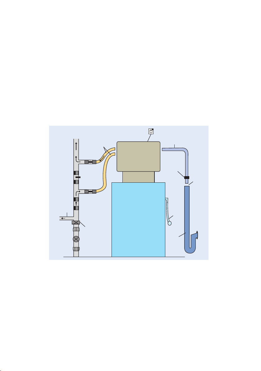
The water softener should be installed as per the diagram below.
Power
CONTROL
VALVE
SALT
STORAGE
TANK
Drain Hose
Drain Clip
Overflow
hose
through
outside
wall
Trapped
Upstand OR
run drain
hose to
external gully
20mm
air gap
Bypass Valve
(shut)
Check Valve
Hard Water
Supply
SOFT WATER
TO SERVICE
Inlet and Outlet
Flexible Hoses
Outlet Valve
(open)
Inlet Valve
(open)
Pressure Limiting
Valve (if required)
STOP TAP ON
INCOMING MAIN
Notes
a. Keep the distance to the drain as short as possible and ensure that the drain and overflow
connections are not subject to freezing.
b. If siting the softener in a cupboard or in a loft ensure that the base is flat strong enough and
adequately supported for the weight of the water softener including salt (approx. 40kg)
c. If the softener is to be sited in a loft it is strongly recommended that the softener be housed
within a 25 gallon storage (safety) tank with a minimum ¾” overflow connection. It is essential
that the overflow connection be as low as possible on the safety tank and in any event below
the height of the overflow connection from the water softener.
d. Check valve. Domestic ion exchange water softeners are considered a Fluid category 2 risk.
Therefore a type EA or EB single check valve should be fitted to the pipework immediately
before the tee feeding the water softener as a suitable backflow prevention.
e. Drinking Water – it is recommended that a hard water supply be used for the kitchen cold
drinking water and any outside taps.
2
CHECK
Check that you have the correct installation kit for your application before commencing the works.
• 15mm Standard Kit (SK-15) – Suitable for Conventional plumbing systems with roof tanks.
• 15mm High Flow Kit (HFK–15) – Suitable for 15mm systems with mains fed appliances
e.g. Combi Boilers, Electric Showers etc.
• 22mm Pressurised System Kit (PSK–22) – Suitable for unvented and pressurised systems
with 22mm plumbing connections.
Available from your merchant supplier.
WATER PRESSURE – Be Careful – Daytime pressure of 3.5 Bar (50 psi) can easily exceed
100psi overnight. If in doubt fit a pressure limiting valve set to 5 bar.
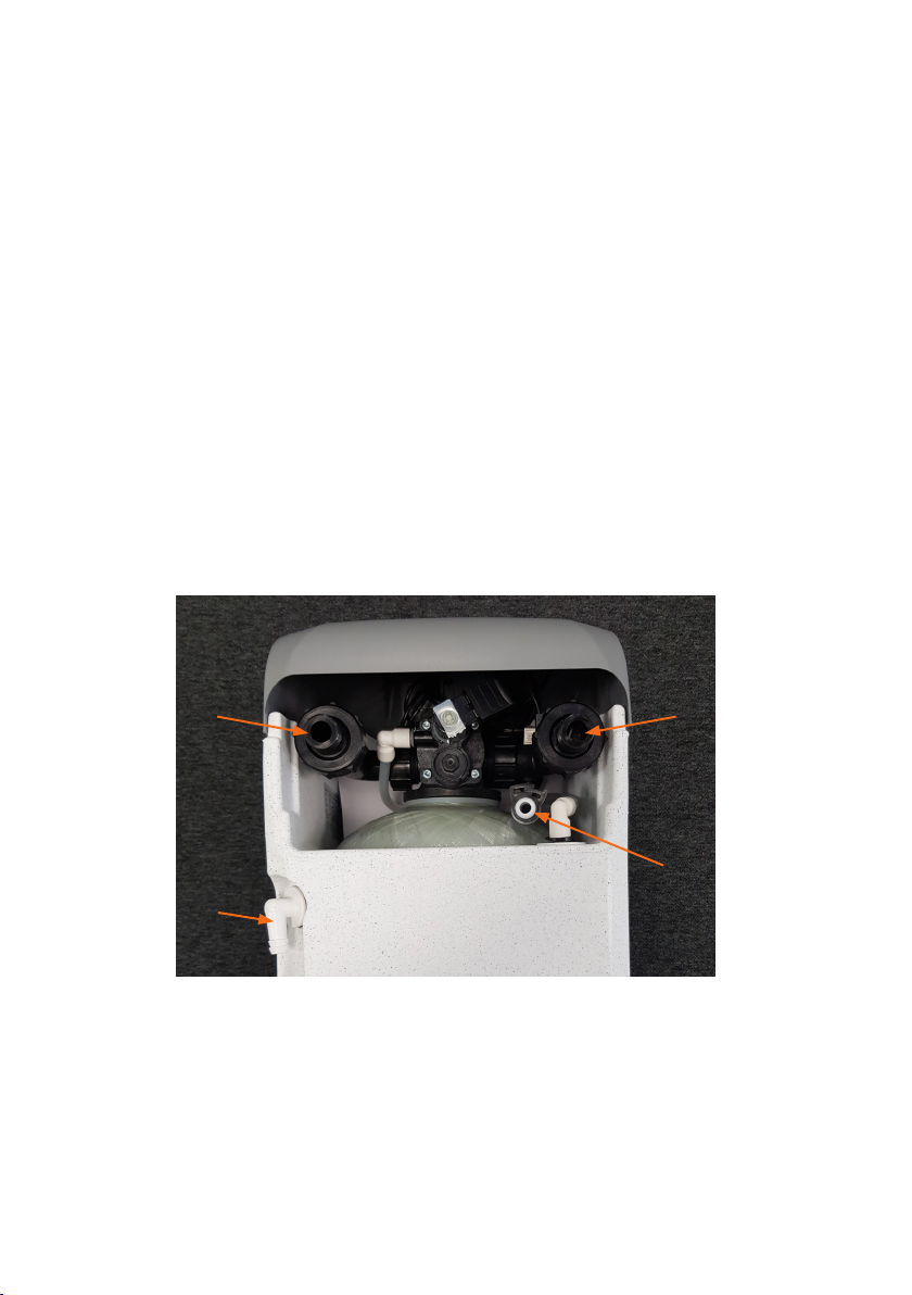
2. Inlet and Outlet Connections
Connect the elbow end of the hoses provided to the inlet and outlet connections on the rear of
the softener.
Important: under no circumstances should you use washing machine hoses or plumb the water
softener in solid copper pipe.
A B
C
A = Inlet Connection
B = Outlet Connection
C= Overflow Connection
D = Waste connection
D
 Loading...