


GREAT WATER Isotemp 0151R, Isotemp 0301R, 0221M, Isotemp 0221R, Isotemp 0401R Installation And Operating Instructions Manual
...
WATER HEATERS
INSTALLATION AND OPERATING INSTRUCTIONS
207 729 8500 TEL 517 813 6509 FAX
PRODUCED BY
GREAT WATER, INC.
BRUNSWICK MAINE
WWW.GREAT-WATER.COM
INFO@GREAT-WATER.COM

Table of Contents
1 Locating the Tank
2 Mounting
3 Connections
3.1 Fittings
3.2 Hoses
3.3 Connections to Engine
3.4 Freshwater System Connections
3.5 Electrical Connections
4 Start Up / Test
5 Maintenance
5.1 Winterization
6 Double Heat Exchanger
7 Technical Data and Dimensions
WWW.GREAT-WATER.COM
INFO@GREAT-WATER.COM
GREAT WATER, INC.
BRUNSWICK MAINE
207 729 8500 TEL
517 813 6509 FAX
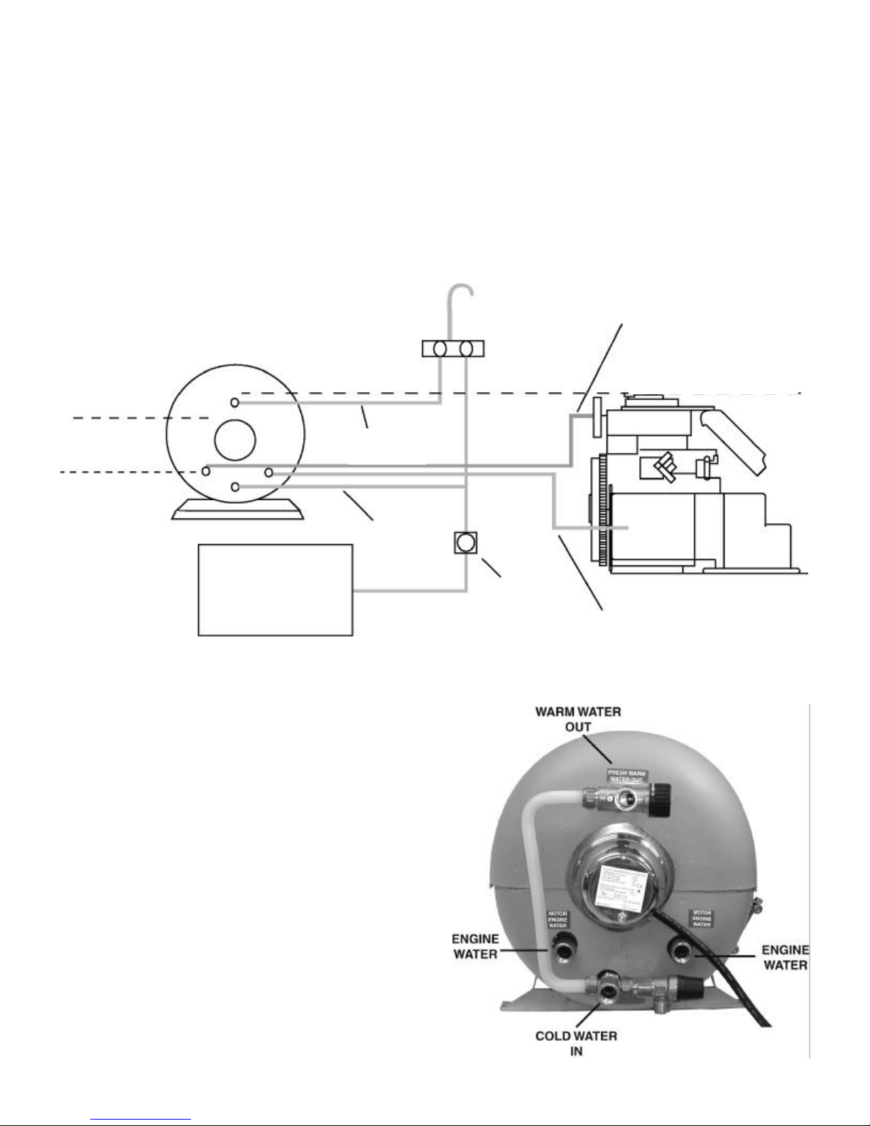
1 Locating the Tank
The water heater can be mounted anywhere on the vessel as long as the connections to the engine heat exchanger are below the engine header tank (Fig. 1). It is best to keep the length of
the heat exchanger hoses short to keep flow resistance and heat loss to a minimum. In many
installations the tank heat exchanger is simply connected in series with the engine coolant circuit. In some installations it is connected in parallel with a flow restrictor/diverter. The
choice depends on the specific re commendations of the engine manufacturer and or installer.
Please consult the manufacturer or dealer of your engine for any recommendations they may
have for connecting to the engine cooling system.
ENGINE
COOLANT
ENGINE HEADER TANK LEVEL
(ABOVE CONNECTIONS TO ENGINE
HEAT EXCHANGER)
HEAT
EXCHANGER LEVEL
(ON MAGIC MODELS)
WATER
HEATER
WATER
TAP
HOT WATER
OUT
HEAT
EXCHANGER LEVEL
(ON REGULAR MODELS)
WATER IN
WATER TANK
Fig. 1
2 Mounting
The Isotemp water heater is designed to give
excellent performance when mounted horizontally. The drain must always be at the lowest
point. The mounting brackets can be adjusted
to the side for mounting the tank on a bulkhead. Always mount the tank to a suitable
shelf or bulkhead and keep in mind the extra
weight of the tank when it is full of water.
It is possible to remove the insulation from the
tank so that the tank can be passed through a
small opening. In order to do this the fittings
and the electrical connection cover must be
removed. The mounting brackets also need to
be taken off and the two halves of the molded
polyurethane insulation can then be removed.
This will reduce the diameter to 10.5 inches.
COLD
COLD
WATER
ENGINE
WATER
PUMP
ENGINE
COOLANT