

Great Wall GW491QE Service Manual

Based on the model GW491Q (4Y) carburetor petrol engine, the GW491QE petrol
engine produced by our company is of one petrol engine able to electrically inject fuel
at multiple points, and is developed from electrical control components made by Delphi
company, USA, and Shanghai United Electronic Company. This model shows a
predominant improvement in aspects of power and economical efficiency, and is in
compliance with GB18352.2-2001 “Limits and measurement methods for exhausts
of pollutants from light vehicles (II) ”(equivalent to European Class-II standard), and
conforms to stipulations at phase III for GB18352.3-2005 “Limits and measurement
methods for exhausts of pollutants from light vehicles (at phase III &IV in China)”
(equivalent to European Class-III standard).
To meet the needs from numerous maintenance /technical / management
personnel, we prepare this “GW491QE Petrol Engine Service Manual” based on the
latest technical materials.
All contents, specifications, and data stated in this manual are the latest information
before printing and this service manual will be subject to a supplemental, revision, and
completion from time to time.
This manual may be used for the reference by mechanics, drivers, and technical /
management personnel as the manual is complete in contents, definite in requirements,
and simple in maintenance.
Constrained by the level of the writer, it’s unavoidable to have some defects in
this manual, and your comments and suggestions are highly appreciated.
Preface

Model GW491QE petrol engine
Service Manual
Engine service &maintenance data......................................................................................
United Electronic engine management system..................................................................
Delphi engine management system......................................................................................
Engine body..............................................................................................................................
Cylinder head............................................................................................................................
Valve mechanism......................................................................................................................
Cooling system.........................................................................................................................
Lubrication system..................................................................................................................
Ignition system.........................................................................................................................
Starting system........................................................................................................................
Charge device..........................................................................................................................
Clutch.........................................................................................................................................
G1
EF.1
EF.2
EM.1
EM.2
EM.3
CO
LU
IG
ST
CH
CL

GI-1
Engine service /Maintenance data
Key technical parameters for model GW491QE petrol engine.......................
Specification &adjustment parameters for key components ...........................
T echnical data for maintenance......................................................................
Tightening torque for fastening elements.........................................................
Troubleshooting............................................................................................
Engine service /maintenance data..................................................................
Page
GI-2
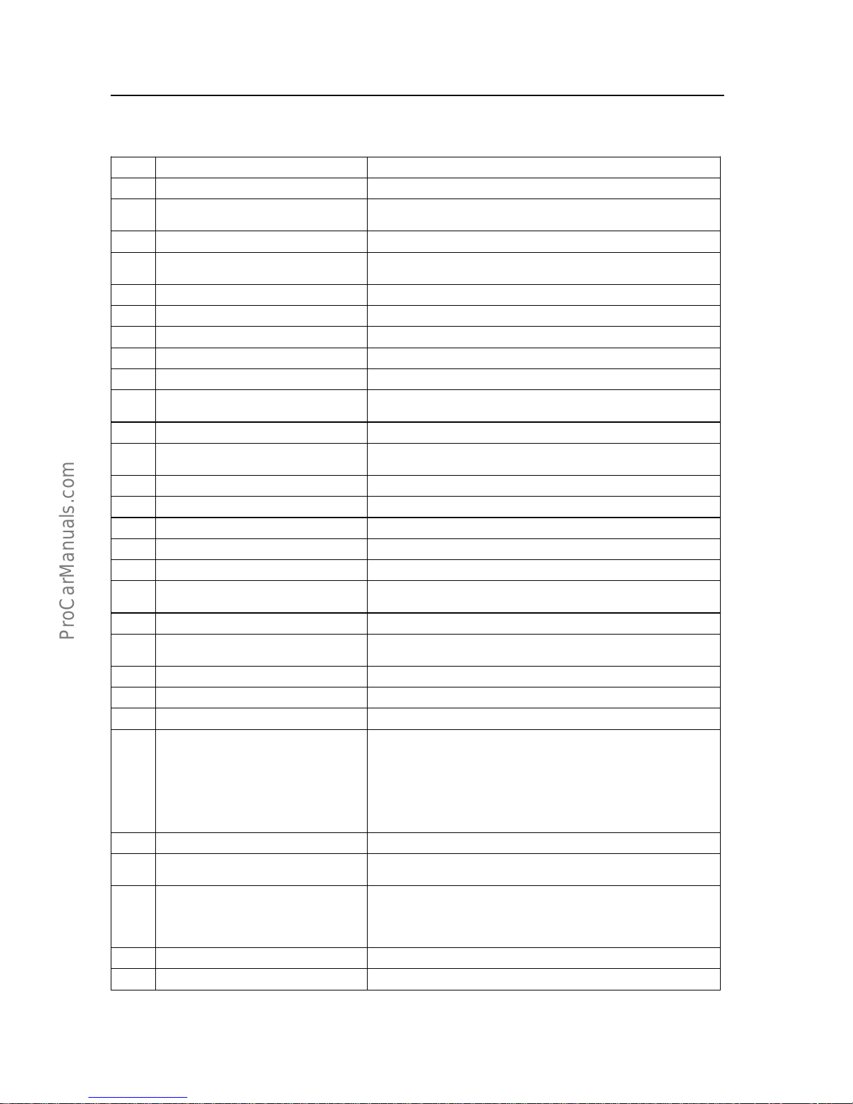
Key technical parameters for Model GW491QE petrol engine
S.N. Item Specification and parameters
1 Model Model GW491QE
2 Pattern
Four-cylinder, inline, water-cooled, overhead valve,4-stroke
petrol engine
3 Fuel supply pattern Electronic controlled jet injection by group at multiple points
4
Measurement method for air intake
amount
Velocity &density type
5 Pattern of combustion chamber Wedge typed
6 Diameter of cylinder bore 91mm
7 Piston stroke 86mm
8 Displacement 2.237L
9 Compression ratio
8.8:1(European class-II)9.1:1European class-III
10 Rated power
78kw/4600 r/min(European class-II)
78kw/4600 r/min(European class-III)
11 Max. torque
190·m/2400~2800 r/min
12 Min. fuel consumption rate
≤265g/kw·h(European class-II)≤250g/kw·h(European
class-III)
13
Fuel specRON Not lower than 93#GB17930-1999
14 Stable idle-speed
750±50r/min
15 Idle-speed control pattern Electronically closed-loop control
16 Piston average velocity 13.18m/s
17 Average valid pressure 874kpa
18
Compression pressure of cylinder
when at 250r/min
1128kpa(European class-II); 1350kpaEuropean class-III
19 Ignition sequence 1-3-4-2
20 Ignition control pattern
Without ignition distributor, and direct ignition under an
electronic control
21 Spark plug clearance 1.0~1.2mm
22 Model of spark plug F6RTC
23 Valve clearance
0mmhydraulic tappet
24
Valve timing:
Inlet-valve open lead angle;
Inlet-valve close lag angle;
Exhaust-valve open lead angle;
Exhaust-valve close lag angle;
12°before the top dead center,
48°before the bottom dead center;
54°before the bottom dead center;
10°before the top dead center;
25 Pattern of lubrication A combined pattern of pressure and splash.
26 Oil spec
SG grade machine oil API10W-40GB11121-1995for petrol
engine
27
Main passage oil pressure
When at idle-speed 750±50r/min
or 3000r/min
49 kpa
(245-490) kpa
28 Oil capacity 4.2L
29 Oil temperature
(85~90)℃
Engine service /maintenance data-Key technical parameters for Model GW491QE petrol engine
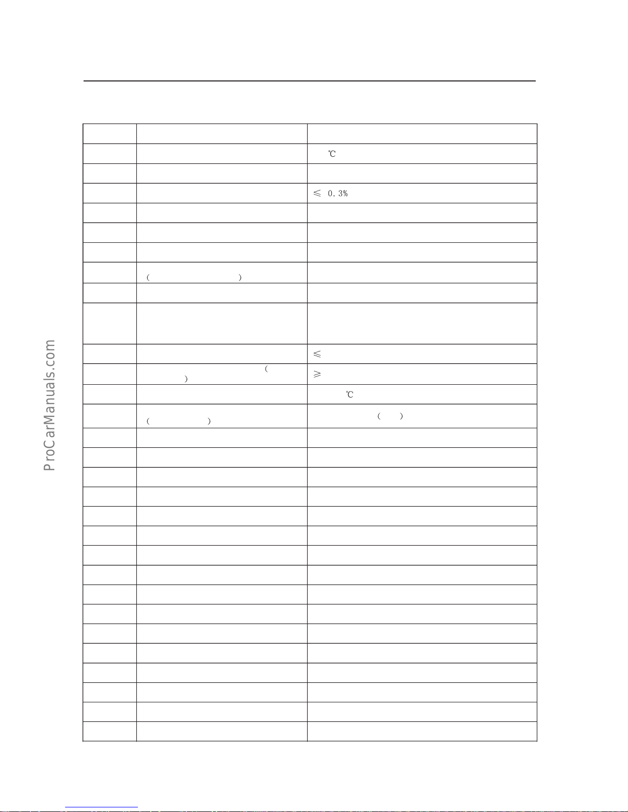
GI-3
S.N.ItemSpecificationandparameters
30Max.oiltemperature
110
31Consumptionrateofoil2g/kw·h
32Fuelconsumptionratioofmachineoil
33CoolingmethodUseforcedwatercirculationforcoolingpurpose.
34Completemass150kg
35PatternofstartupElectrical
36
Exteriordimension
length×width×height
(754.5×518×651)mm(electronicfan)
37
Dualidle-speedemission
GB18285-2005
38
Emissioncontrollevelwhenunder
operatingcondition
Withathree-waycatalytic converter,andaclosed
loopcontrolforair/fuelratio,andthewithlight-duty
vehiclesatisfiesrequirementsfromGB18352.2-2001
andGB18352.3-2005standards.
39Differencebetweencylinders
98kpa
40
Vacuuminsideairintakepipe
whenat
idle-speed
53.3kpa
41Temperatureofoutletcoolingwater(80~90)
42
Tensiondegreeoffanbelt
Pressure98N
Beltdeviation:7~8mm
Engineservice/maintenancedata-keytechnicalparametersforModelGW491QEpetrolengine
GI-4
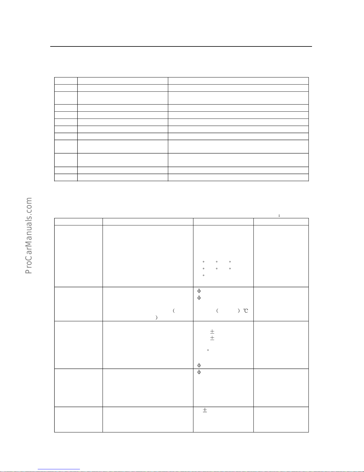
Engineservice/maintenancedata-specification/adjustmentparameters/maintenancetechnicaldata
dataforkeycomponeats
Specification/adjustmentparameters
forkeycomponents
S.N.ItemSpecificationandparameters
1SparkplugF6RTC
2Startermotor
Deceleratingtypewhenunderanelectromagnetic
controlU=12VP=1KW
3GeneratorandvoltageregulatorU=14VI=65A/90A
4PetrolpumpBlade-typeelectricalpump
5OilpumpRotortyped
6CoolingwaterpumpCentrifugaltype
7ThermostatWaxtype
8Petrolfilter
Steelcover,withsuperhighmolecularweight,and
filtrationcore
9Oilfilter
Full-flow&integraltype,screwinstalledfiltration
papercores
10IgnitioncoilU=12V
11ClutchDiaphragmspringtype
Maintenancetechnicaldata
1.Enginemechanism
Unit
mm
NameTestitemsStandardvalueUselimit
Cylinderhead
Planenessonthecontactsurfaceof
body;
Planenessonthecontactsurfaceof
manifoldpipe;
Slopeangleofvalveseat
Airintake
Airexhaust
Contactangle
Contactwidth
0.05
0.05
30
,45,60
30,45,60
45
1.2~1.6
0.15
0.10
Valveguide
Innerdiameter
Exteriordiameter
Increasedsize0.05
Temperaturewhenchanging
onthe
sideofcylinderhead
8
13
13.088~13.100
Heatto
80~100
Valve
Wholelengthofvalve
Airintake
Airexhaust
Angleofvalveworkingsurface
Airintakeandexhaust
Diameterofvalverod
Airintake
108.20.10
108.5
0.10
44.5
8
107.7
108.0
Valve
Airexhaust
GapofvalverodAirintake
Airexhaust
Edgethicknessofvalveplate
Airintake
Airexhaust
8
0.025~0.060
0.030~0.065
0.10
0.12
0.5
0.8
Valvespring
Freelength
Installationheight
Installationtension
Nonperpendicularity
47
0.5
40.6
(282~345)N282
2.0
+0.030
+0.010
+0.050
+0.038
-0.015
-0.030
-0.020
-0.035
GI-5
Engineservice/maintenancedata-specification/adjustmentparameters/maintenancetechnical
dataforkeycomponents
NameTestitemsStandardvalueUselimit
Rockerandaxis
forvalve
Innerdiameterofrockerhole
Diameterofrockershaft
Gapbetweenrockerandrockershaft
18.5
18.5
0.018~0.0460.08
Intakemanifold
pipe
Planeness0.050.4
Timinggear/chain
gear
Whenthesaggingofchainis98N,
Diameterofrearchainwheel(withchain)
Crankshaft
Camshaft
Lengthofchainwarpafteruse
Thicknessofchaintensioner
Thicknessofshockabsorber
13.5
58.2
113.23
291.4
12.5
5
Camshaftand
bearing
Max.circumferentialradialbeat
eccentricity
HeightofcamMin.convexvalue
Airintake
Airexhaust
AxialdiameterofcamshaftNo.1
No.2
No.3
No.4
No.5
Clearanceofaxialdiameter
Axialclearance
0.05
38.6791
38.6869
46.5
46.25
46
45.75
45.5
0.025~0.081
0.07~0.22
0.10
0.30
Cylinderblock
Planeness
Diameterofborehole
increasedsize0.50
increasedsize0.75
increasedsize1.00
91
0.05
91.24
91.74
91.99
92.24
Pistonand piston
ring
Pistondiameter
increasedsize0.50
increasedsize0.75
increasedsize1.00
Clearanceofpiston
Sideplayofannulargroove
Openinggapofpistonring
Firstgasring
Secondgasring
Oilring
90.938~90.968
91.425~91.455
91.675~91.705
91.925~91.955
0.042~0.062
0.03~0.075
0.20~0.40
0.35~0.55
0.20~0.80
0.065~0.085
1.11
1.07
1.10
Pistonpinand
connectionrod
Axialclearanceofmainbodyfor
connectionrodonbigheadend
Axialclearanceofconnection-rod
cover
Bendofconnectionrodevery100mm
Distortofconnectionrodevery
100mm
Innerdiameterofconnectionrodon
smallhead
Exteriordiameterofpistonpin
Gapofinnerholeonsmallheadside
ofpistonpinandconnectionrod
0.16~0.31
0.021~0.051
0.03
0.03
22.010~22.016
22.003~22.006
0.004~0.013
0.18~0.32
0.05
0.15
+0.013
0
-0.018
-0.033
0
-0.2
0
-0.23
-0.025
-0.041
-0.025
-0.041
-0.025
-0.041
-0.025
-0.041
-0.025
-0.041
+0.030
0
GI-6
Engineservice/maintenancedata-maintenancetechnicaldata
Unitm
m
NameTestitemsStandardvalueUselimit
Crankshaftand
bearing
Axialclearance
Thicknessofthrustwasher
Increasedby0.125
Increasedby0.250
Mainjournaldiameter
Clearanceofmainjournaldiameter
journaldiameterofconnectionrod
journalclearanceofconnectionrod
Circumferentialplayofmainaxial
diameter
Roundness/diameterofcolumn,
formainaxialdiameterand
connectionroddiameter
0.02~0.22
2.450~2.490
2.575~2.615
2.700~2.740
58
0.021~0.053
48
0.021~0.053
0.03
0.01
0.30
0.10
0.10
0.06
0.02
2.Coolingsystem
NameTestitemsStandardvalueUselimit
Capacityof
coolingfluid in
engine
7.9L
Radiator
Pressurewhenthepressurerelief
valveofcoverisopened.
(73.6~103)kpa
Min.value
notlessthan
58.9kpa
Thermostat
Temperaturewhenvalveisopened.
Liftdistanceofvalve95
(8084)
8mm
<76
<8mm
Transmissionbelt
Bendingdeflectionoftransmission
beltwhena98Nforceisapplied.
Newbelt
Usedbelt
(5~7)mm
(7~8)mm
3.Lubricationsystem
NameTestitemsStandardvalueUselimit
Capacityofoil
Totalcapacityofoil
dryinjection
Re-injectionaftertheremoval
Withoutoilfilter
Withoilfilter
4.2L
3.0L
3.5L
Oilpump
Clearancebetweenrotorandpump
Clearancebetweenmastery rotor
andslaveryrotor
Endclearanceofrotor
(0.10~0.15)mm
(0.07~0.12)mm
(0.03~0.07)mm
>0.20mm
0.20mm
0.15mm
Pressureofoil
(750
50)r/minatidle-speed
(2000
50)r/min
(3000
50)r/min
Max.temperatureofoil
49kpa
170kpa
(245.2~490.3)kpa
110
<245.2kpa
0
-0.015
0
-0.015
GI-7
Engineservice/maintenancedata-tighteningtorqueforfasteningelements
4.Ignitionsystem
NameTestitemsStandardvalueUselimit
Sparkplug
Model
Clearance
F6RTC
1.0~1.2mm
High-tension
wiringResistance16k
/m
5.Startingsystem
NameTestitemsStandardvalueUselimit
Starter
Ratedvoltage
Outputpower
Zero-loadcharacteristics
sizeof
currentspecifiedwhenit’s11.5V
RectifierExteriordiameter
DepthofTchannel
Circumferentialradialplay
Lengthofelectricbrush
Workloadofspring
12V
1kw
90A
30mm
(0.50~0.80)mm
0.05mm
13mm
(17.5~23.7)N
>90A
<29mm
<0.20mm
>0.05mm
<8.5mm
<17.56N
6.Chargedevice
NameTestitemsStandardvalueUselimit
Battery
Densityofelectrolyteforbattery
Whenfullchargeofbatteryat20
1.25~1.27
ACgenerator
Resistanceofrotorcoils
Diameterofslipring
Exposedlengthofelectricbrush
4.0
(32.3~32.5)mm
12.5mm
<32.1mm
5.5mm
RegulatorAdjustmentvoltageat20(13.95~14.4)V
Drivingbelt
A98Nbending-deflectionforceis
appliedtodrivingbeltbetweenAC
generatorandwaterpump.
Newbelt
Usedbelt
(5~7)mm
(7~8)mm
Tighteningtorqueforfasteningelements
1.Tighteningtorqueforspecialcomponents
FrequentlytightenedsparepartsN
m
ValverockerarmshaftcylinderheadM8
Cylinderheadbolt10-M12
1.25
3-M8
Airintake/exhaustmanifoldpipecylinderhead
Sparkplug
cylinderhead
Camshafttimingchaingearcamshaft
Camshaftflange
cylinderbody
Waterpump
boxoftimingchainchamber
24
90
20
50
18
90
18
18
GI-8
Engineservice/maintenancedata-Tighteningtorqueforfasteningelements
FrequentlytightenedsparepartsNm
Waterpumpcylinderbody
Boxoftimingchainchamber
cylinderblockBolt
Nut
Bearingcoverofconnectionrod
connectionrod
Bearingcoverofcrankshaft
cylinderblock
Crankshaftbeltpulley
crankshaft
Flywheel
crankshaft
Oilbottomoilpan
cylinderblock
Generatoradjustmentsupport
cylinderblock
Rearoil-sealseat
cylinderblock
Drainplugofoilpan
40
18
18
50
80
160
85
13
40
12
20~25
2.Standardbolttighteningtorque
Tighteningtorque
Gradediametermm
screwpitch
mm
hexagonal-headed
bolt
Nm
hexagonalflangebolt
Nm
4T
6
8
10
12
14
16
1
1.25
1.25
1.25
1.5
1.5
5
12.5
26
47
74
115
6
14
29
53
84
5T
6
8
10
12
14
16
1
1.25
1.25
1.25
1.5
1.5
6.5
15.5
32
59
91
140
7.5
17.5
36
65
100
6T
6
8
10
12
14
16
1
1.25
1.25
1.25
1.5
1.5
8
19
39
71
110
170
9
21
44
80
125
7T
6
8
10
12
14
16
1
1.25
1.25
1.25
1.5
1.5
10.5
25
52
95
145
230
12
28
58
105
165
8T
8
10
12
1.25
1.25
1.25
29
61
110
33
68
120
9T
8
10
12
1.25
1.25
1.25
34
70
125
37
78
140
GI-9Engineservice/maintenancedata-Troubleshooting
T
ighteningtorqu
e
Gradediametermm
screwpitch
mm
Hexagonal-headed
bolt
Nm
Hexagonal
flangebolt
Nm
10T
8
10
12
1.25
1.25
1.25
38
78
140
42
88
155
11T
8
10
12
1.25
1.25
1.25
42
87
155
47
97
175
Commonfailuresandtroubleshooting
1.Enginenotstartorstartwithdifficulty
CauseoffailureMethodsofelimination
1.Failureinstartingsystem
1Batteryhasinsufficientvoltage
2Batterynotconnectedwell
3Fusebroken
4Failureinstarter
5Failureinignitionswitch
2.Failureinignitionsystem
1High-tensiondampingwiringdamagedor
notconnectedwell.
2Ignitioncoildamaged
3Inappropriateclearancebetween
bothelectrodesofsparkplug.
4Sparkplugisdampedorthe
electrodehascarbondeposit.
5Insulatoronsparkplugisruptured.
3.Failureinthefuelsupplysystem
1Petrolpipelineisblockedorwithair
resistance.
4.Engineunderabadcondition
1Valveisleakingairordamagedby
burning.
2Padofcylinderisdamaged.
3Piston,pistonring,andcylinderare
muchabraded.
4Intakemanifoldisleakingair,or
vacuumplugislost.
5Pipelinefrom the ventvalve of
crankshaftboxtothethermalbaffle
ofsolenoidvalveisleakingair.
1.
(1)Chargewithpower.
(2)Cleanwiringterminalsandtightenbatteryline.
(3)Changethefuse
(4)Repairorchangestarter
(5)Repairorchangeignitionswitch
2.
1Changethehigh-tensionresistanceline
2Changetheignitioncoil
3Adjusttheclearancebetweenbothelectrodes.
4Haveitbakedorclearawaythecarbondeposit.
5Changethesparkplug
3.
1Washthepetrol-oilpipelineorclearawaytheair
resistance.
4.
1Repairorchangevalve
2Changeit.
3Repairorchangeit.
4Checktheintakemanifoldpipeandgasket,tighten
thenut,andblockwellthevacuumtube.
5Fixtheconnectionpipetightly.
2.Enginecannotbeacceleratedorisslackaccelerated.
CauseoffailureMethodsofelimination
1.Failureintheignitionsystem
1Sparkplugnotworkingwell
2Thehigh-tensiondampingwiringis
damaged.
3Theignitioncoilsaredamaged.
2.Failureinengine
1Valveisleakingairordamagedby
burning.
2Cylinderisunderabadcompression
condition.
3Padofcylinderisleakingair.
4Intakemanifoldpipeisleakingair.
1.
1Checkorchangethesparkplug
2Changethehigh-tensiondampingwiring
(3)Changetheignitioncoil
2.
1Repairorchangevalve
2Repairorchangerelevantspareparts
3Changethecylinderpad
4Checktheintakemanifoldpipeandgasket,and
tightenthenut.
GI-10
3.engineisslack.
CauseoffailureMethodsofelimination
1Engineisunderabadcompressioncondition.
1Valveisleakingair.
2Hydraulicretainingcolumnnot
workingwell.
3Valvespringiswithaninsufficient
forceorevenbroken.
4Padofcylinderisleakingair.
5Pistonringisstuckorbroken.
6Pistonorcylinderismuchabraded.
2
Failureinignitionsystem
Sparkplugnotworkingwell.
3
Petrolsupplyisblocked.
1Petroltankhascontaminantdeposits.
2Petrolpipeisblocked.
3Petrolfilterisblocked.
4Petrolpumpnotworkingwell.
5Airexistsinthefuelsystem.
4
Petrolnotconformingtothespecification.
5
Intakemanifoldpipeisleakingair.
6
Airenteringtheairpipeisinsufficient.
1Airfilterisblocked.
2Chokevalvehasnotbeenopened
completely.
7.Enginetoohot.
1
1Abradethevalve.
2Checkorchangeorwashthehydraulictappet
.
3Changethevalvespring.
4Changethecylinderpad.
5Changethepistonring.
6Repairorchangerelevantspareparts.
2
Clean,adjustorchangethesparkplug.
3
1Cleanorchangetheoiltank.
2Cleantheoilpipeormakeitthrough.
3Changethepetrolfilter.
4Repairorchangepetrolpump
5Checkandtighteneachjoint.
4
Makeitsubjecttotechnicalspecifications.
5
Checktheintakemanifoldpipeandgasket.
6
1Washthecover,andcleanthefiltrationcoreby
purging.
2Repairandadjustitscontrolmechanism.
7
Refertothe“methodsofelimination”incase
offailure“enginetoohot”.
4.Engineisbackfiredordeflagrated.
CauseoffailureMethodsofelimination
1Failureinignitionsystem
1Jointontheignitionlineisloose.
2Sparkplugnotworkingwell.
3Theheatcharacteristicsofsparkplug
areinappropriate.
2Inappropriatecontentofmixedgas
1Petrolsupplyisblocked.
3
Failureinthevalvemechanism
1Valveisstuckorleakingair.
2Thevalvehydraulicretainingcolumn
notworkingwell.
3Valvespringiswithinsufficient
strength.
4
Thecoverofcylinderunderabadcondition
1Combustionchamberhascarbon
deposit.
2Thecoverofcylinderisoverhotorthe
coolingisinsufficient.
3Thecoverofcylinderisdamaged.
5.Thehigh-tensionresistancelineis
misconnectedordamaged.
1
1Checkandtighteneachjoint.
2Wash,adjustorchangethesparkplug.
3Replacewithsparkplughavingappropriateheat
characteristics.
2
1Refertoarticle3inthe“engineslack”.
3
1Abradeorchangethevalve.
2Changeorwashthehydraulic retaining
column.
3Changethevalvespring.
4
1Clearawaythecarbondeposit.
2Clearairawayfromthecoolingwatersleeve.
3Changethecylinderhead
5
Correctorchangeit.
Engineservice/maintenancedata-Troubleshooting
GI-11
Engineservice/maintenancedata-Troubleshooting
5.Unstableidle-speedforengine
CauseoffailureMethodsofelimination
1Withairleakage
1Theintakemanifoldpipeisleakingair.
2
Failureinignitionsystem
3
Failureinvalvemechanism
1Badsealingofvalve;
2Hydraulictappetisnotworkingwell;
3Clearancebetweenthevalverodand
thevalveguidingrodismuchbig.
4Thepadofcylinderisleakingair.
5
Thesupplyofpetrolisnotsmooth.
1
1Checktheintakemanifoldpipeandgasket.
2
Article2of“enginenotstartorstartwithdifficulty”.
3
1Abradethevalve.
2Changethehydraulicretainingcolumn.
3Changethevalveortheguidingrodofvalve
4Changethecylinderpad
5
Refertoarticle3of“engineslack”.
6.Abnormalsoundoccurredinengine
CauseoffailureMethodsofelimination
1Clearanceproducedduetothefailurein
hydraulicretainingcolumn
2Pistonpintoomuchloose.
3
Piston,pistonring,andcylinderabraded
toomuch.
4
Thebushingofconnectionrodabradedtoo
much.
5
Mainbushingabradedtoomuch.
6
Thrustpieceofcrankshaftabradedtoomuch.
7
Muchclearancebetweencamshaftandthe
thrustplateofcamshaft.
8Timingchainandtimingchainwheelabraded
toomuch.
9Chaintensionernullandvoid.
10Toomuchcarbondepositinthecombustion
chamberofcylinder.
11
Petrolisnotconsistenttothespecification.
1Checkandchangethehydraulicretainingcolumn.
2Changethepistonpinorpiston.
3
Check,repair,andchangetherank.
4Changeit.
5
Changeit.
6
Changeit.
7
Changethethrustplateofcamshaft.
8Changeit.
9Changeit.
10.Clearawaythecarbondeposit.
11
Followthetechnicalspecifications.
7.Largeconsumptionofpetrol
CauseoffailureMethodsofelimination
1Pipelinehasleakageofpetroloil.
2
Airfilterisblocked.
3
Failureinignitionsystem
1Errortimingofignition.
2Failureinsparkplug.
4Badcompressionofengine.
5Slipperyofclutch.
1Tightenconnectorsandclampsateachpoint.
2
Checkandcleantheairfilter.
3
1Adjustthetiming.
2Checkorchangethesparkplug
4Refertoarticle1of“engineslack“
5Checkandadjusttheclutch.
GI-12
Engineservice/maintenancedata-Troubleshooting
Engineservice/maintenancedata-TroubleshootingLargeconsumptionofmachineo
il
CauseoffailureMethodsofelimination
1Leakageofmachineoil
1Theoil-dischargeboltonbottomoilpan
isloose.
2Thefixingboltonbottomoil panis
loose.
3Gasketofbottomoilpanisdamaged.
4Fixingboltforthecoverofchainwheel
chamberisloose.
5Sealingringofshieldcoverforvalve
chamberisdamaged.
6Front/backoil seal forcrankshaftis
damaged.
7Fixingboltforoilpumpisloose,or
gasketisdamaged.
8Fixingboltfor oil filterisloose, or
gasketisdamaged.
2
Combinedpistonoilringsareabradedtoo
muchorevendamaged.
3
Pistonandcylinderareabradedtoomuch.
4Oilsealonvalverodisdamaged.
5
Valverodandguidingrodareabradedtoo
much.
6
Theventilationsystemofcrankshaftboxis
blocked.
7
Engineisrunningwithsmallloadathigh
speedforalong-termperiod.
1
1Tightentheoil-dischargebolt.
2Tightenthefixingbolt.
3Changethegasket.
4Tightenthefixingboltorchangethegasket.
5Changethesealingring
6Changetheoilseal
7Tightenthefixingboltorchangethegasket.
8Tightenthefixingboltorchangethegasket.
2
Changethecombinedpistonoilrings.
3
Sentitonservice.
4Changethevalveoilseal
5
Changethevalveandguidingrod.
6
Check,cleanandmakeitthrough.
7
Avoidtheenginerunningwithsmallloadandat
highspeedwhenpossible.
9.Enginenotflameouraftertheignitionswitchisclosed.
CauseoffailureMethodsofelimination
1Enginetoohot.
2
Sparkplugtoohot.
3
Toomuchcarbondepositincombustion
chamber.
1
Haveenginerunningatidlespeed,decreasethewater
temperaturebelow80
,andclosetheignitionswitch.
2
Selectthespecifiedmodelofsparkplug.
3
Clearawaythecarbondeposit.
10.Enginetoohot
CauseoffailureMethodsofelimination
1.Insufficientamountofcoolingfluid
2.Fanbeltlooseordamaged
3.Failureinwaterpump
4.Failureinthermostat
5.Radiator,cylinderblock, cover/pipeline/
passageofcylinderblockedorleaked
6.Failureinsilicon-oilclutch
7.Machineoilinsufficientorthedensityislow;
8.Toomuchcarbondepositincylinderheador
combustionchamber;
9.Exhaustsystemnotthrough
1.Addcoolingfluid
2.Adjustthetensiondegreeofbeltorchangethebelt.
3.Repairorchangethewaterpump.
4.Changethethermostat.
5.Clean,repairorchangerelevantspareparts.
6.Checkorchange.
7.Addorchangethemachineoil.
8.Clearcarbondepositaway.
9.Cleanorchangesparepartsfortheexhaustsystem.
GI-13
Engineservice/maintenancedata-engineservice/maintenancedata
11.Pressureofmachineoilistoolow
CauseoffailureMethodsofelimination
1Theleakageofmachineoil
2Muchinsufficientmachineoilorthedensity
istoolow;
3Thetemperatureofmachineoilisbeyondthe
limit.
4Failurecausedbythepressurereliefvalveon
oilpump.
5Failurecausedbyoilpump
6Oilfilterisblocked,orconnection
pipeisleakingoil.
7Oilfilterisblocked.
8Failurecausedbytheoilpressuresensor
9Mainbushing,thebushingorcamshaftfor
connectionrodabradedtoomuch.
10Failureofoilmanometer.
11Toomuchoilleakageatrockershaftor
wherechainistensioned.
1Refertoarticle1 in“Toomuchmachineoil
consumption”;
2Addmachineoil,orchangethemachineoil;
3Checkthecoolingsystemwhentheenginecools
down.
4Sendthepressurereliefvalveonservice.
5Repairorchangetheoilpump.
6Wash,clean,andtightentheconnector.
7Changetheoilfilter
8Changetheoilpressuresensor
9Changethebushingorbearing.
10Changethemachineoilmanometer
11Check,repair,andfixit.
Engineservice/maintenancedata
1.SSTspecialmaintenancetools
Note
sort
A=usedintheroutinerepairduringtheinspectionofvehicles,orusedasgeneraltools;
B=usedintheoverhaulingastodismantlecomponents;
C=usedintherareandspecialworkswhicharenotsimilartoAandB.
Chapter
Outlined
diagram
PartNo.Partname
Sor
t
IVVVIVII VIIIIXXXIXII
Rem
ark
09032-00
100
Toolsusedtocutoil
sealonbottomoilpan
A
09043-88
010
8mmhexagonalnut
spanner
A
09201-41
020
Tools used tochange
theoilsealonvalverod
B
09201-60
011
Toolsusedtodismantle
andrepairguidingrod
onvalve
A
09202-43
013
Springpresserforvalve
A
09213-31
021
Removerforbeltpulley
oncrankshaft
A
09213-70
010
Toolsusedtofix the
beltpulleyonto
crankshaft
A
09215-00
100
Toolsusedtodismantle
andrepairthecamshaft
bearing
C
09216-00
020
Belttension-gauge
A
09216-00
030
Belttensioncable
GI-14
Engineservice/maintenancedata-engineservice/maintenancedata
Toolsusedtodismantle
andchangethepiston
pins
Mainbody
Spring
sleeve A
guidingrod A
guidingrod B
Toolsusedtochange
theoilsealbeforethe
crankshaft
Toolsusedtochange
theoilseal afterthe
co-axis.
Spannerforoilfilter
Tools usedtorepair
radiator
Spannerusedtoadjust
idle-speedscrews
Rockersupporttools
Valvepushrodtools
Cone-shapedtoolsused
forthecrankshaft
bearingoninjection
pump
Toolsusedtodismantle
thesplinedshaftfrom
injectionpump
Oil-sealremover
Toolsusedtofix
flangesinpairs
Universalremover
Beltpulley
for
crankshaft
GI-15Engineservice/maintenancedata-engineservice/maintenancedata
Clutch
guidingtools
Toolsusedto
dismantle
guidebearing
from
crankshaft
Toolsusedto
dismantle
guidebearing
from
crankshaft
Toolsusedto
alignwith
clutchfilm
spring
2.SSMspecialrepairdata
NameofmaterialProductNo.Usage,etc.
1282Bsealant
1282BThreebondorsimilarproducts
08823-00100
Cooling-waterbypassflange
Rear-endcoverplateforcylinder
1324bond
1324Threebondorsimilarproducts
08833-00070
Thermostatformanifoldpipe
Boltsforflywheelordrivingplate
Fixingscrewsforinductioncoil
1324bond
1324Threebond
242Letaiorsimilarproducts
08833-00080
Cooling-fluiddischargevalveforengine
Oilpressureswitch
EF.1-1
Page
Description of system.................................................................................................
Precautions to the maintenance of electric-injection system..........................................
Analysis of the function /principal /failure for system parts &components .....................
General troubleshooting and steps to engine ...............................................................
Criterion to flashing code /mounting torque of components within M1.5.4 system........
Description of the diagnosis function on M7.9.7 system failure....................................
M7.9.7 system service &diagnosis flow process based on fault code..........................
United Electronic engine management system
EF.1-2
Model GW491QE petrol engine adopts BOSCH Motronic1.5.4 and Motronic7.9.7 engine management system
for electric-injection: As for the exhaust, the former is in compliance with European Class-II standard, and the
latter is in compliance with European Class-III standard.
BOSCH Motronic1.5.4 engine management system for electric-injection
As one set of advanced engine management system, M1.5.4 system has one engine electronic control unit
abbreviated to ECU used as the control center, and is able to measure various working parameters of
engine using appropriate sensors installed at different position of engine, to precisely control the oil injection
amount and the ignition lead-angle as per control programs set in engine electronic control unit, and to have
engine working with best performance under various conditions, ie. optimum dynamic output, most costeffective oil consumption, and best tail gas exhaust.
M1.5.4 system is subject to a multi-point oil injection control as per some sequence, and its control strategy
covers: starting control, closed-loop control of idle-speed, closed-loop control of air /fuel ratio, carbon-canister
control, transition working condition control, ignition angle control, knock control, air-conditioner control, slide
oil cut control, over-speed oil cut control, heating &protection control by three-way catalytic converter, and
system self-diagnosis, etc. The system has provided ABS, automatic gear box, air bag, etc, with applicable
communication interfaces, and is with theft-prevention function. The system is composed of three parts: sensor
air inlet pressure /temperature sensor, throttle position sensor, cooling-fluid temperature sensor, knock sensor,
oxygen sensor LSH25, rotating speed sensor, phase sensor
, actuator idle-speed adjustor EWD3, oil injector
EV6, electrical fuel pump, fuel pressure adjustor DR, carbon-canister control valve TEV, and ignition coil
ZSK
, and ECU electronic controller.
BOSCH Motronic7.9.7 engine management system for electric-injection
The key feature of M7.9.7 engine electronic control management system is the application of a control
strategy based on torque aimed at linking a number of various controlled objects together. And this is the only
fixed method to have various functions integrated on ECU flexibly in accordance with the model of engine and
vehicle.
Basic components within the M7.9.7 engine electronic control system include: electronic controller
,
air inlet pressure /temperature sensor, air mass flowmeter, cooling-fluid temperature sensor, throttle position
sensor, phase sensor, rotating speed sensor, knock sensor, oxygen sensor, idle-speed adjustor, oil injector,
electronic fuel pump, fuel pressure adjustor, oil pump support, fuel distributing pipe, carbon-canister control
valve, and ignition coil.
M7.9.7 engine management system, namely a petrol engine electronic control system, is available with many
control characteristics fit for operator, vehicle, and device, and is the combination of open-looped control and
closed loop control
feedback to provide various control signals while engine is running. Key function of
system includes:
1. An application physical model of basic engine management function
(a) System structure based on torque
(b) The cylinder loading capacity to be determined by the air inlet pressure sensor /air-flow sensor
(c) Improve the function as to control the gas mixture under a static or dynamic status;
(d)
typed closed-loop control
(e) Fuel injection by cylinder as per some sequence
(f) Ignition timing, inclusive of knock control by cylinder
Description of system
UASE Electronic Control Engine Management System -System Introduction

EF.1-3
(g) Exhaust control function
(h) Heating function of catalytic converter
(i) Carbon-canister control
(j) Idle-speed control
(k) Limped back home
(l) Speed sensing through an incremental system
2. Additional function
(a) Theft-detector function
(b) Connection between torque and exterior system
eg. transmission mechanism, or vehicle dynamic control
(c) Control over several types of engine parts and components
(d) Provide a matching interface across EOL-programming tool and maintenance tools.
3. Online diagnosis OBD
(a) Fulfill a series of OBD function
(b) A management system used for diagnosis function
UASE Electronic Control Engine Management System -System Introduction
EF.1-4
cases)
Precautions to the maintenance of electric-injection system
UAES Electronic Control Engine Management System-Notes for Electronic Injection
System Service

EF.1-5
6. Precautions to the replacement with new ECU:
(a)Prior to the change of ECU, remove the negative electrode line from accumulator jar.
(b)Check whether the power supply and the overlapped steel on ECU wiring harness are under a normal condition.
(c)As for the first engine starting process after new ECU has been installed, do not start the engine immediately,
instead, open the ignition switch before wait for ten seconds to restart the engine, Following a successful
starting process, perform a ECU self-learning as per following sequence:
Have the engine running at idle-speed for at least ten minutes;
Flameout for at least ten minutes;
Open the ignition switch rather than an immediate starting process, and wait for at least ten seconds;
UAES Electronic Control Engine Management System-Notes for Electronic Injection
System Service
EF.1-6
Analysis of function /principal /failure for system parts &components
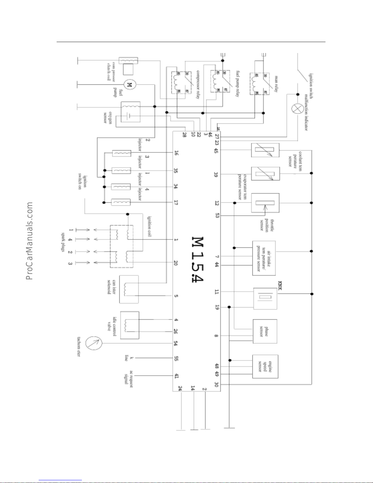
1. System circuit diagram and the definition of ECU Pins
(a)United Electronic M1.5.4 system circuit diagram
United Electronic engine management system-Analysis of function /principal /
failure for system parts &components
EF.1-7
United Electronic engine management system-Analysis of function /principal /
failure for system parts &components
EF.1-8
United Electronic engine management system-Analysis of function /principal /
failure for system parts &components
(b)Definition of ECU pins within Motronic 1.5.4 system
S.N. Description of function Type S.N. Description of function Type
1 Ignition coil(pin 2) Output 28 Signal of oxygen sensor(pin 4) Inpu t
2 Power ground Ground 29
Pin A on step motor, or
at EWD3.1 case: idle pin
Output
3
Holding coil of oil pump relay (pin
86)
Output 30 Sensor ground Ground
4
Pin B on step motor or
pin 1 on EWD3
Output 31
Holding coil of
cooling-fan relay, or
when without fan relay:idle pin
Output
5
Control valve of
carbon-canister(pin 2)
Output 32 Idle pin
6 Function reserved 33 Idle pin
7
Signal of inlet-air pressure
sensor(pin 4)
Input 34 Injector (pin 2) for cylinder 4 Output
8 Signal of phase sensor Input 35 Injector (pin 2) for cylinder 3 Output
9 Signal of vehicle speed 36 Function reserved
10 Ground of oxygen sensor(pin 3) Ground 37 Power supply of main relay(pin 87)
Power
supply
11 Signal of knock sensor(pin 1) Input 38 Idle pin
12 Internal power supply(5V)
Power
supply
39
Signal of air-conditioner temperature
sensor
Input
13 Function reserved 40
Connect to the electromagnetic clutch
relay output for air-conditioner
compressor(pin 87), or short-circuit
connected to Pin 1 of cylinder 4
depending on the type of vehicle
Input
14
Ground of driving stages for oil
injector and carbon-canister control
valve
Ground 41 Signal o A/C switch Input
15 Function reserved 42 Idle pin
16 Oil injector (pin 2) for cylinder 2 Output 43 Idle pin
17
Oil injector (pin 2) for cylinder 1
Output 44
Signal of air-inlet temperature sensor(pin
2)
Input
18 8A fuse-accumulator voltage
Power
supply
45 Engine water-temperature signal(pi n 1) Input
19 Electronic ground Ground 46 Signal of main relay Output
20
Second ground of idle pin, and
dual-spark ignition coil(pin 1)
Output 47 Idle pin
21
Pin D on step motor, or at EWD3.1
case; idle pin
Output 48
Ground of Hall sensor(pin 1),or
Ground of rotating speed sensor (pin B)
Ground
22
Electromagnetic clutch relay for
holding coil of air-conditioner
compressor
(pin 86)
Output 49
Ground of Hall sensor(pin 1),or
ground of rotating speed sensor (Pin A)
Input
23
Fault indicator lamp, or at a case
without fault indicator lamp; idle
pin
Output 50 Pre-set
24
Power ground for other driving
stages(air-conditioner compressor,
motorized fuel pump)
Ground 51
Correction of basic ignition timing, or at
a case without ignition distributor: idle
pin
Input
25 Function reserved 52
Ground enhanced, or at a case without
ignition distributor: idle pin
Input
26
Pin C on step motor,
or Pin 2 on EWD3
Output 53 Signal of throttle position sensor(pin 3) Input
27 Key switch Input 54 Engine tachometer output Output
55
Fault diagnosis interface
(line K)
Input/Output
EF.1-9
UnitedElectronicenginemanagementsystem-Analysisoffunction/principal/
failureforsystemparts&components
cDefinitionofECUpinswithinMotronic7.9.7system
PinConnectionpointTypePinConnectionpointType
1
Heatingpoint
ofoxygensensor
Output42
Air-conditioner
temperaturesensor
Input
2Ignitioncoil2Output43
3IgnitiongroundGround44IntermittentpowersupplyInput
445IntermittentpowersupplyInput
5Ignitioncoil1Output46
Solenoidvalveof
carbon-canister
Output
6
Oilinjectionnozzle4(cylinder
No.2)
Output47
Oilinjectionnozzle3(cylinder
No.4)
Output
7
Oilinjectionnozzle2(cylinder
No.3)
Output48
8INoutputOutput49
950Fancontrol1Output
1051Electronicground2Ground
1152
12UninterruptedpowersupplyInput53Electronicground1Ground
13IgnitionswitchInput54
14MainrelayOutput55
15
Engine
rotating-speedsensorA
Input56
16
Throttlepositionsensor
Input57
Air-conditioner
compressorswitch
Input
17Sensorground1Ground58
18OxygensensorInput59VehiclespeedsignalInput
19KnocksensorAInput60
20KnocksensorBInput61Powerground1Ground
2162
2263IntermittentpowersupplyInput
2364PhaseDonstepmotorOutput
2465PhaseAonstepmotorOutput
2566PhaseBonstepmotorOutput
2667PhaseConstepmotorOutput
27
Oilinjectionnozzle1(cylinder
No.1)
Output68
2869OilpumprelayOutput
29DetectorlampOutput70
Air-conditioner
compressorrelay
Output
3071DiagnosislineK
Output,
input
3172
32A5Vpowersupply2Output73
33A5Vpowersupply1Output74
34
Engine
rotating-speedsensorB
Input75Air-conditionerswitchInput
35Sensorground3Ground76
36Sensorground2Ground77
Polechanger
forboosterpump
Input
37Inlet-airpressuresensorInput78
3879PhasesensorInput
39
Enginecooling-fluidtemperature
sensor
Input80Powerground2Ground
40Air-inlettemperaturesensorInput81
41
EF.1-10
United Electronic engine management system-Analysis of function /principal /
failure for system parts &components
resistance
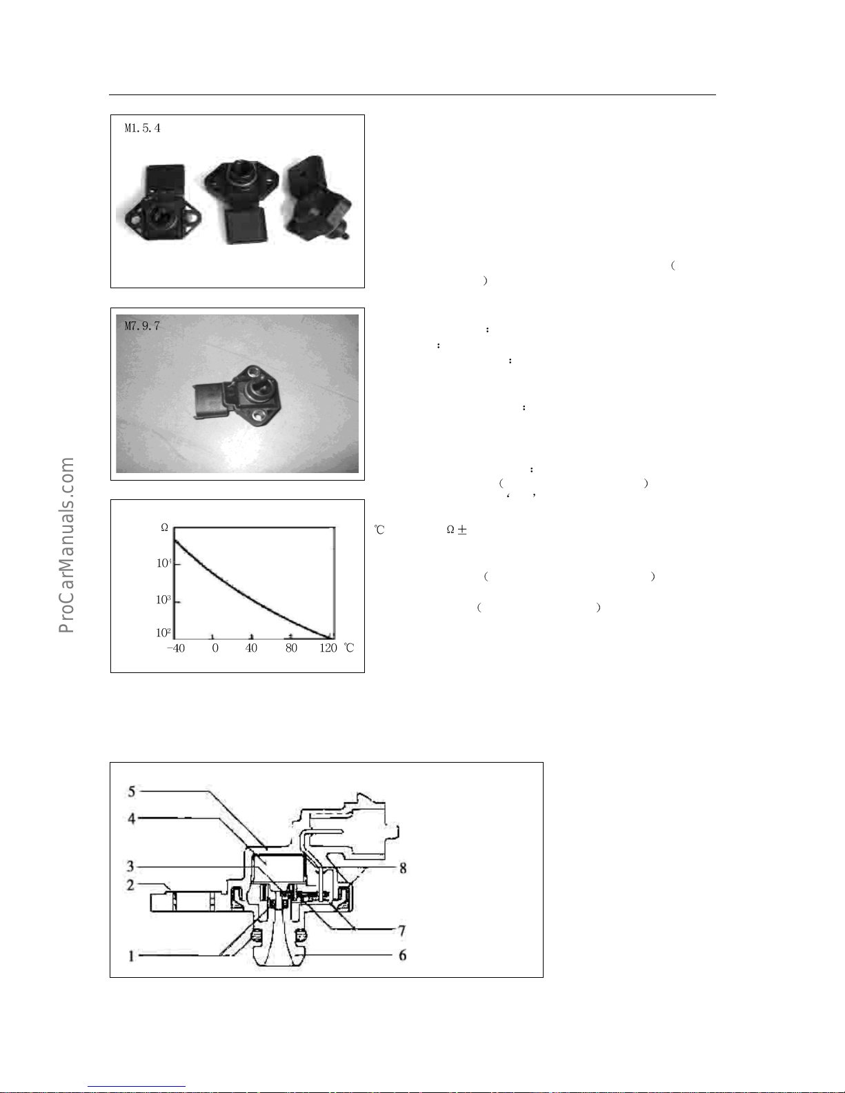
2. Air inlet pressure /temperature sensor DS-S-TF
(a) Function: this sensor is used to measure the absolute-pressure /
temperature of inlet manifold, and to provide information concerning engine
load and air-inlet temperature.
(b) Principal: The part measuring the inlet-air pressure is of a piezoelectric
sensor, which is able to provide the controller with “load signal” depending
on the difference of atmospheric pressure and the pressure of inlet manifold;
And the controller will produce a 5V voltage, and a 0-5V voltage will be
feedback to the controller depending on the different inlet-air pressure.
The part measuring the inlet-air temperature is one NTC typed
negative
temperature coefficient sensor, whose resistance will be changed by the
change of air-inlet temperature. And the sensor will transmit a voltage
reflecting the change of air-inlet temperature to the controller.
(c) Installation position on the inlet manifold.
(d) Symptom flameout, inferior idle-speed, etc.
(e) Cause of general failures
There’s abnormal high voltage or reversedly large current during operation;
V acuum elements are damaged during maintenance.
(f) Precautions to maintenance
during maintenance, it’s prohibited to
use highly pressurized air to impact vacuum elements; Whereby the sensor
needs to be changed in case of failure, check whether the output voltage and
current from generator is under a normal condition.
(g) Simple measurement method
Temperature sensor part: after disconnection of joint Have digital
multimeter adjusted to the ohm position, and connect two pens with
Pin 1 and Pin 2 of sensor respectively; And the rated resistance when at 20
shall be 2.5k 5%, Other corresponding resistances may be measured
from the characteristic curve shown above. A simulation method may be
applied during measurement, details as shown below: send air to the sensor
using an electric blower
Keep some distance when blowing , and observe
the change of sensor resistance, and the resistance shall be decreased.
Pressure sensor part: after connection of joint Have digital multimeter
adjusted to the DC voltage position, and connect the black pen to ground,
the red pen to Pin 3 &4 successively. When under an idle-speed status, a 5V
reference voltage will be produced on Pin 3, and an approx. 1.3V voltage
will be produced on Pin 4; When under a zero load status, slowly open the
throttle valve, and the voltage on Pin 4 will be with slight changes; Quickly
open the throttle valve, the voltage on Pin 4 will reach approx. 4V
instantaneously before being decreased to 1.5V gradually.
characteristic curve of temperature sensor
temperature
1.sealing ring
2. stainless liner
3. PCB plate
4. sensing element
5. shell body
6. stress support
7. welded connection
8. bonded connection
EF.1-11
United Electronic engine management system-Analysis of function /principal /
failure for system parts &components
Performance data
Measurement Value
Min. Typical Max.
Unit
Scope of testing pressure 20 115 kPa
Operation temperature -10 125 ℃
Operation supply voltage 4.5 5.0 5.5 V
Current when US=5.0V 6.0 9.0 12.5 mA
Load current in output loop -0.1 0.1 mA
Load resistance to ground or to accumulator 50 kΩ
Response time 0.2 ms
Weight 27 g
(h)Technical &characteristic parameter
Limit data
Measurement Value
Min. Typical Max.
Unit
Tolerable supply voltage
16 V
Tolerable pressure
500 kPa
Tolerable storage
temperature
-40 +130 ℃
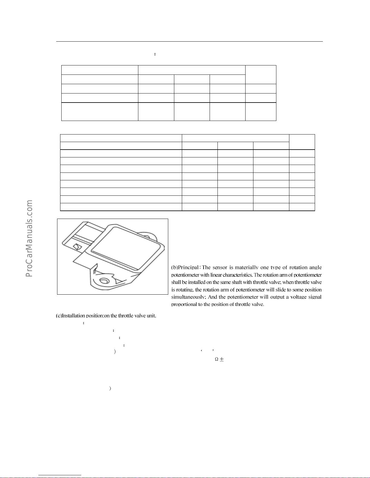
3. Throttle position sensor DKG
(a)Function: this sensor is used to provide ECU with information concerning
the rotation angle of throttle valve. Based on such information, ECU may
obtain relevant information concerning engine load, working condition, (eg.
starting, idle-speed, reverse, partial load, full load), acceleration and
deceleration.
(d)Symptom bad acceleration, etc.
(e)Cause of general failures
artifical failure.
(f)Precautions to maintenance
take note of the installation position.
(g)Simple measurement method
(after disconnection of joint Have digital multimeter adjusted to the ohm position, connect two pens with Pin 1 and Pin 2 of
sensor respectively; And the resistance value at room temperatrure shall be 2k
20%; Connect two pens with Pin 1 and Pin 3 of
sensor respectively, rotate the throttle valve, and the resistance value will be subject to a linear change with the opening of throttle
valve; When connected with Pin 2 and Pin 3, an opposite situation will be produced.
Remark: When observing the change of resistance value, the main focus is to observe whether the resistance value has a larger leap.
(after connection of joint
Open the ignition switch rather than to start the engine, have digital multimeter adjusted to the DC
voltage position, and connect the black pen to ground, the red pen to Pin 2, and a 5V reference voltage shall be produced; Connect the
red pen to Pin 3, and the voltage shall be at about 0.3V when throttle valve is at a full closed position, or about 3V when throttle valve
is at a full open position.
EF.1-12
UnitedElectronicenginemanagementsystem-Analysisoffunction/principal/
failureforsystemparts&components
(h)Technical&characteristicparameter
Limitdata
MeasurementValueUnit
MechanicrotationanglebetweentwoextremepositionsDegree
AvailableelectricalrotatinganglebetweentwoextremepositionsDegree
Allowablecurrentonslidingcontactarm
Storagetemperature
Allowablevibrationacceleration
Performancedata
MeasurementValue
Min.TypicalMax.
Unit
TotalresistancePin1-2
Protectionresistanceonslidingcontactarm(when
slidingcontactarm
isatzeroposition
Pin2-3)
Operationtemperature
Supplyvoltage
Voltageratioonrightextremeposition
Voltageratioonleftextremeposition
IncrementrateofUp/Us
fortherotationangleofthrottlevalve
degree
Weight
EuropeanClass-II
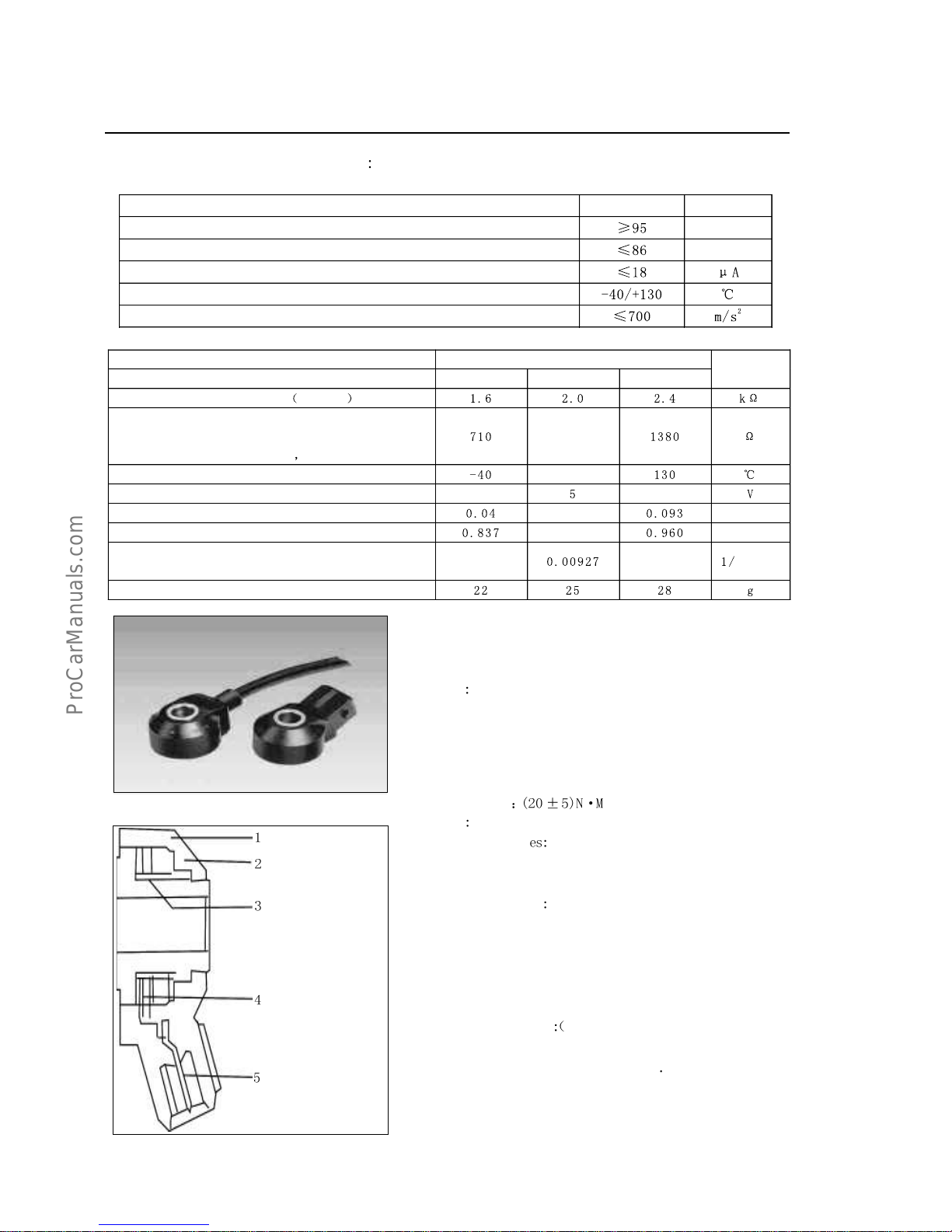
4.KnocksensorKS
(a)Function:thissensorisusedtoprovidetheelectroniccontrollerECU
withengineknockinformationforaknockcontrolpurpose.
(b)Principal
Beingonetypeofvibrationaccelerationsensor,theknock
sensorisinstalledontheenginebody;Itssensingelementisofone
piezoelectriccrystal,towhichthevibrationonenginebodymaybetransmited
viamassblockinsidethesensor.Underthevibrationstressofmassblock,a
voltagewillbeproducedontwopolefacesofpiezoelectriccrystaltoconverse
thevibrationsignalintovoltagesignal
(d)Mountingtorque
(e)SymptomBadacceleration,etc.
(f)Causeofgeneralfailur
Thesensormightbecorrodedwhencontacting
withvariousliquidsforlongtermperiod,suchasmachine-oil,cooling-fluid,
braking-fluid,water,etc.
Precautionstomaintenance
Thesensormusthaveitsmetalsurfaceclosely
contactedwiththeenginebody,andanytypeofwasherisunallowablefor
useduringinstallation.Duringthesignalcablepavementforsensor,it’s
notedthatdonotallowanysyntonyproducedonsignalcabletoavoid
rupture.Alwaysavoidtheconnectionofhigh-voltagecurrentbetweenPin1
andPin2ofsensor,otherwise,piezoelectricelementswillbedamaged.
Simplemeasurementmethod
afterdisconnectionofjoint£©Havedigital
multimeteradjustedwithPin1andPin3respectively.Andtheresistance
valueatroomtemperatureshallbegreaterthan1M¦¸Havedigitalmultimeter
adjustedtothemillivoltposition,anduseasmallhammertogentlyknock
ontheareanearbytheknocksensor,andavoltagesignaloutputwillbe
produced.
EuropeanClass-III
1.shockblock
2.exteriorcover
3.piezoelectric
ceramicbody
4.contacthead
5.electricalplug
 Loading...