

Great Wall 4G64S4M Service Manual

Preface
This manual is specially made for those who
engage in automobile maintenance and repairing.
Following general rules of system division of vehicles
(engine, clutch, etc.), this manual adopts the division
methods by major assembly. In order to describe all
parts belonging to an assembly, assemblies are further
divided into several parts.
Brief introductions, specifications, main points
of adjustments, mounting and dismounting,
assembling and disassembling of the assembly
components are covered in this manual. On the top of
the first page of all assemblies are the content, through
which the needed information can be easily found.
All explanations and specifications in this
manual is the latest till the date of printing.
GENERAL 00
ENGINE 11

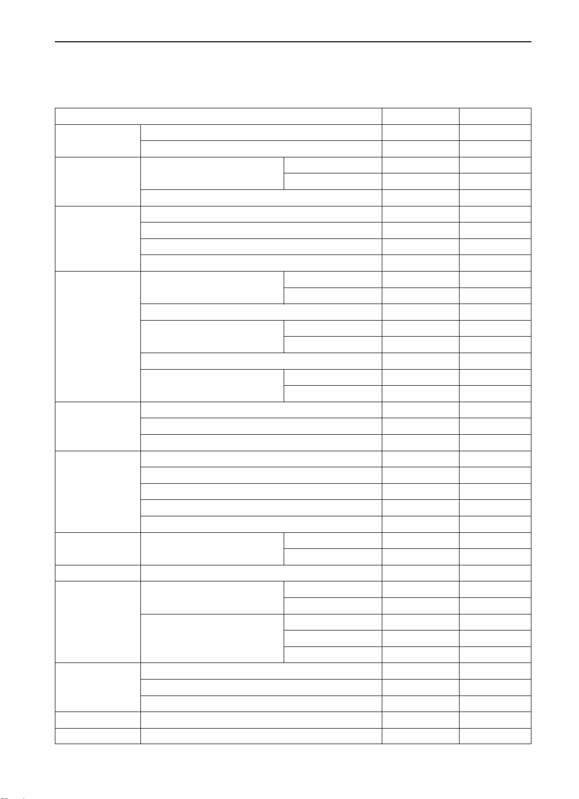
General
Contents
page
Guide on Using the Manual.......................................... 00-3
Engine .......................................................................... 00-5
Tightening Torque......................................................... 00-6
Sealant (FIPG) ............................................................. 00-7
00-1
00
GENERAL GUIDE ON USING THE MANNUAL
00-2
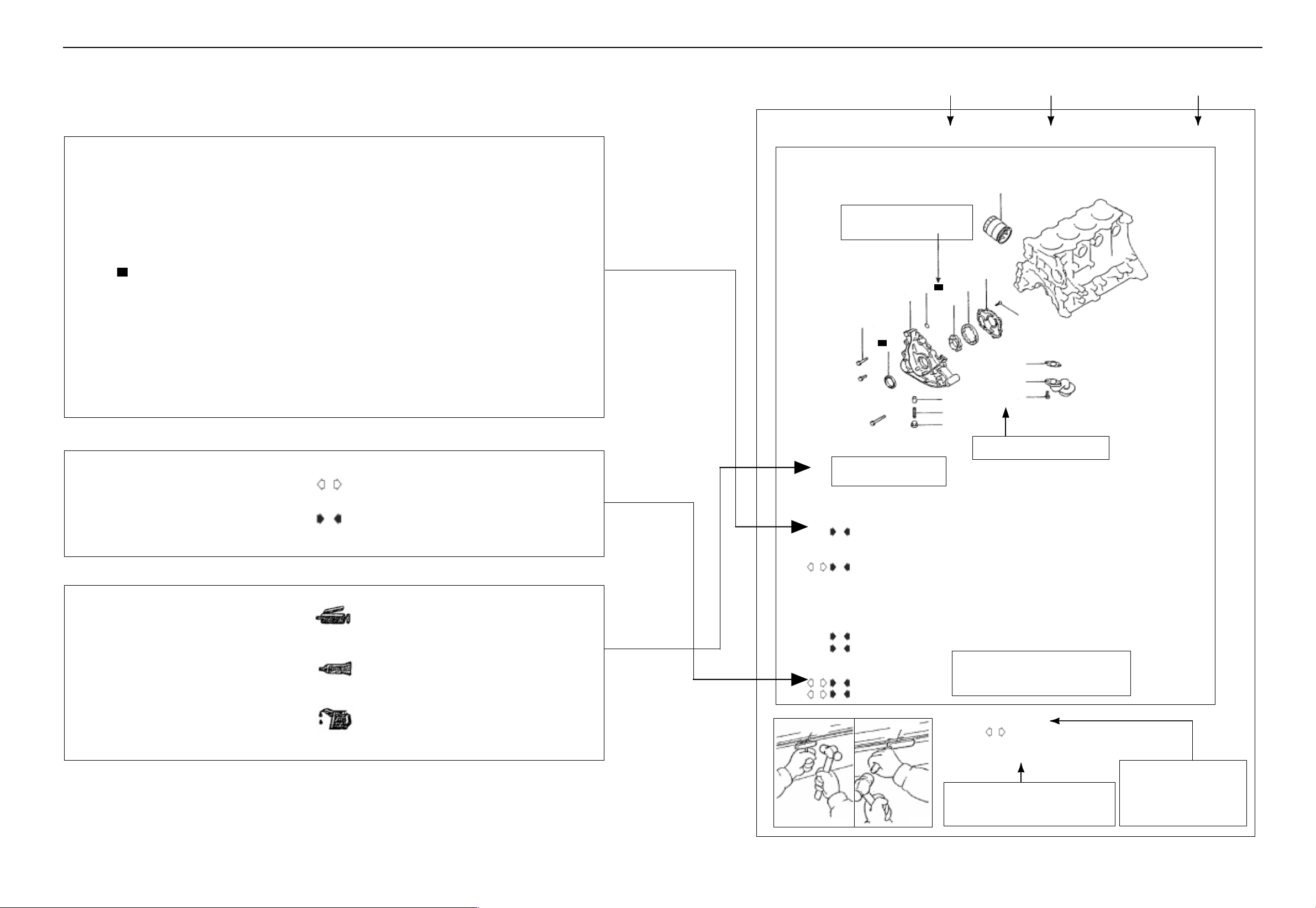
Guide on Using the Manual
Maintaining Steps
(1) Profile plots are provided for you to
understand the installation of each
component.
(2) Use reference number of the parts to
show operation steps, mark the parts
that can not be used repeatedly (marked
as ) and the tightening torque.
N
Dismantling Steps: Corresponding number of parts to the
number in the figure of composing parts to show
the dismantling steps.
Disassembly Steps: Corresponding number of parts to the
number in the figure of composing parts to show
the disassembly steps.
Mounting Steps: Mounting steps should be indicated when the
mounting may not in the reverse order with
dismantling steps. Otherwise, the mounting steps
can be omitted.
Assembly Steps: Mounting steps should be indicated when the
mounting may not in the reverse order with
dismantling steps. Otherwise, the mounting steps
can be omitted.
Front Cover, Oil Pump
Dismantling and Mounting
Stands for part that may not
be used repeatedly
11
1.4Kg.m
N
10
Grouping name Section Name Page
Engine Front cover, Oil pump 11-33
1
13
14
N
12
15
1
6
5
9
8
7 4.5Kg.m
1.9
Kg.m
Division of Notes for Maintaining
When there are notes for maintaining, standard value and usage of special tools, detailed explanation is given.
Marks for Lubricant, Sealant and
Adhesive
Indicate in the figure of composing parts the
location where lubricant, smearing or supplying of sealant and adhesive are to be
applied.
Indicates Notes for dismantling or disassembly
A
available.
Indicates Notes for mounting or assembly
A
available.
Lubricating grease
[Means all-purpose lubricating grease if not
specially indicated otherwise.]
Sealant or adhesive
Engine oil or gear oil
Dismantle steps:
BA
BA
MD998727
Smear the engine oil on all the
movement parts while assembling
1. oil filter
E
2. oil drain plug
3. oil plug washer
4. oil pan
DA
5. oil filter screen
6. oil filter screen washer
7. overflow valve plug
8. overflow valve string
9. overflow valve core
10. oil seal
C
11. oil pump shell
B
12. O-ring
13. oil pump shell cover
14. outer rotor
15. inner rotor
MD998727
stands for tightening torque
These numbers are corresponding to the
numbers in the steps of dismantling,
disassembly, mounting and assembly.
Disassembly notes:
Oil pan disassembly
A
After you take down the bolt , disassembly the oil pan with
special tool.
9EN0040
DILD583 DILD584
These English letters corresponds to the
letters in the steps of dismantling,
mounting, disassembly and assembly.
Explanations are given for the
maintaining essentials and
notes for dismantling and
mounting, disassembly and
assembly.

OVERVIEW ENGINE
ENGINE MODEL
VEHICLE MODEL ENGINE
MODEL DISPLACEMENT TYPE
HOVER CUV 4G64-D-Y7 2,351 ML FOUR CYLINDERS, IN-LINE, SOHC
00-5
00-6
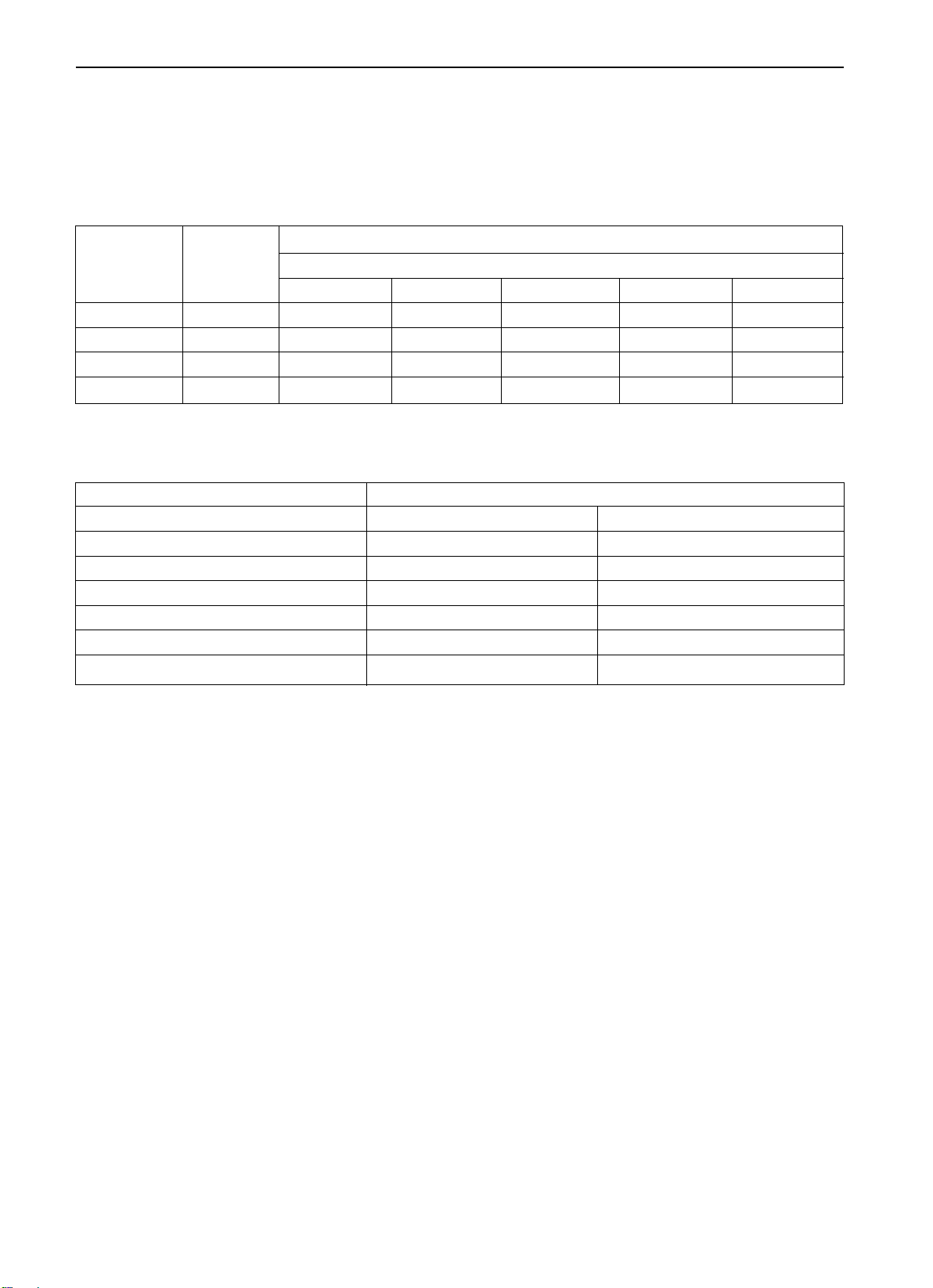
OVERVIEW TIGHTENING TORQUE
Tightening Torque
The common tightening torque is shown in the list.
Tightening torque of special parts is shown at the beginning of each group.
Tightening torque of bolts and nuts
Diameter
of bolt
M6 1.0 0.9 1.3 1.1
M8 1.25 1.1 1.8 3.0 1.4 2.4
M10 1.25 2.0 3.4 6.0 3.0 5.0
M12 1.25 3.6 6.2 10.8 5.5 9.0
Tightening torque of taper thread
Thread Dimension Torque (Kg. M)
NPTF 1/16 0.5 0.8 0.8 1.2
PT 1/8 0.8 1.2 1.5 2.2
PT 1/4 2.0 3.0 3.5 4.5
NPTF 1/4 2.0 3.0 3.5 4.5
PT 3/8 4.0 5.5 5.5 7.5
PT 1/2 7.0 10.0 12.0 16.0
Thread
pitch
Bolt (with spring washer) Valve bolt
Head mark 4 Head mark 7 Head mark 10 Head mark 4 Head mark 7
Light alloy Cast iron, steel
Torque (Kg. M)

OVERVIEW SEALANT(FIGP)
00-7
Sealant (FIPG)
Sealant is used on many parts of the engine and gearbox. The using of sealant is for the purpose of adequately sealing,
therefore, much attention should be paid to the dosage, position and the surface of sealant. Insufficient dosage of sealant
may result in leakage, while superfluous dosage of sealant may result in the overflow of sealant and jam the passage of
water or oil, or narrow the passage. So, in order to avoid leaking on the mounting surface, it is absolutely necessary to
keep the correct dosage that may keep from disconnection.
FIPG used in the engine is of Room Temperature Vulcanizing (RTV) and is provided in the way of 100-gram tube (Piece
No. MD970389, for engine use). RTV may vulcanize after reaction with the water content in the air; therefore, it is usually
used on the metal end face.
Disassembly
Components assembled with sealant may be disassembled without using a special method. However, in some cases, it
is necessary to lightly hit the components with a mallet or similar tools so as to break sealant on the coupling face, or
use a smooth thin sealant knife to hit into the joint face gently without damaging the coupling face. When dismounting
the engine oil pan, use special tool for dismounting oil pan (MD998727).
Cleaning of Sealing Surfaces
Remove rubbish on the sealing surface with a sealant knife or a steel wire brush. Be sure the sealing surface is flat and
smooth, and there isnt any oil stain of foreign object on it. Remember to remove the sealant inside the mounting hole
and the threaded holes.
Essentials for Smearing
Matters to be taken into consideration while assembling components with FIPG.
Smear sealant equally within the prescribed diameter to cover around the mounting hole. Sealant that is not yet vulcanized
can be removed. After the installation, the sealant should be sufficiently vulcanized (approximately 1 hour or so). Do
not apply oil on the smeared part or wet or startup the engine during this period.

11-1
Engine
Contents
page
General ........................................................................ 11-2
Specifications ............................................................... 11-3
Maintaining Standard ................................................... 11-3
Tightening Torque ........................................................ 11-5
Sealant ......................................................................... 11-7
Special Tools................................................................ 11-8
AC Generator and Ignition System .............................. 11-11
Timing Toothed-belt ..................................................... 11-14
Fuel System ................................................................. 11-23
Intake Manifold ............................................................. 11-25
Exhaust Manifold and Water Pump.............................. 11-26
Rocker Arm and Camshaft ........................................... 11-28
Cylinder Head and Valve ............................................. 11-34
Front Cover and Oil Pump ........................................... 11-40
Piston and Connecting Rod ......................................... 11-49
Crankshaft, Cylinder Block and Flywheel..................... 11-55
AC Generator ............................................................... 11-62
Starter .......................................................................... 11-66
Throttle Body ................................................................ 11-70
11
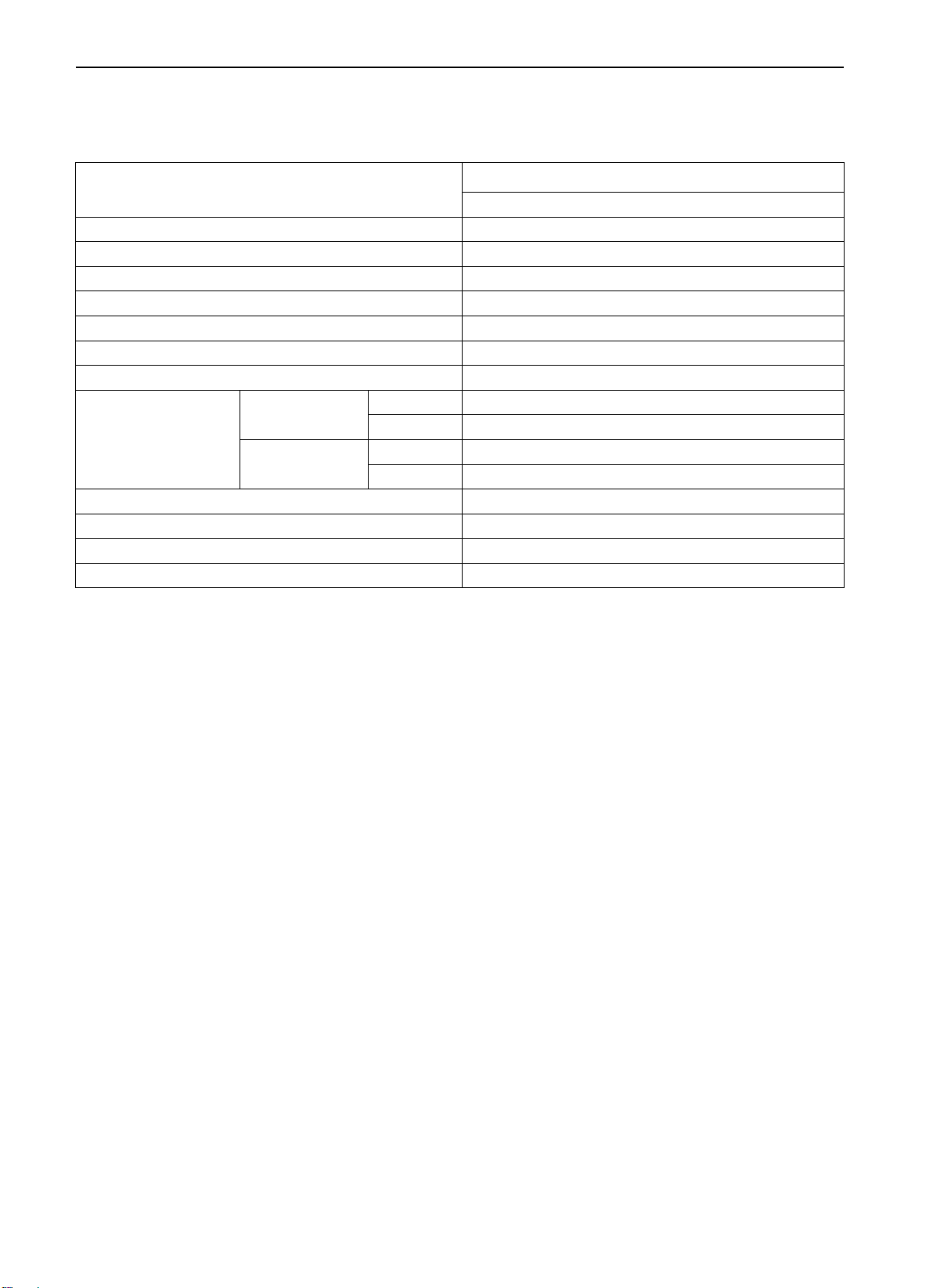
11-2
General
ENGINE SPECIFICATION
Items
Type In-line OHV, SOHC
Number of Cylinders 4
Combustion Chamber Single Pitch Roof
Total Displacement ml 2,351
Cylinder Bore mm 86.5
Stroke mm 100.0
Compression Ratio 9.5
Intake valve
Valve Timing
Exhaust valve
Lubrication system Compression supply, full flow filtering
Type of oil pump Gear type
Cooling system Water cooling forced circulation
Type of water pump Centrifugal impeller
On 18before top dead center
Off 53 after bottom dead center
On 50 before bottom dead center
Off 18 after top dead center
4G64 S4 MPI
Specifications
ENGINE SPECIFICATION
Specifications
Maintenance Standard
Items Standard Value Limit Value
Generator
Toothed-belt
Camshaft Air exhaust 36.83 36.33
Cylinder Head
Valve
Convex value of tensioner arm 12
Press-in value of tensioner arm (98~196N) 1
Height of cam Air intake 37.39 36.89
Shaft diameter 45.0
Planeness of Bottom Surface 0.03 0.2
Surface lapping limit*Total lapping of cylinder block and head
Total height 119.9 120.1
Length of cylinder head bol 97.4 99.4
Edge thickness
Diameter of valve stem 6.0
Radial clearance between valve
stem and valve guide
Inclination 45 45.5
Intake 1.0 0.5
Exhaust 1.2 0.7
Intake 0.02 0.05 0.10
Exhaust 0.03 0.07 0.15
* 0.2
11-3
Unitmm
Height
Free Height 51.0 50.0
Valve Spring Working pre-tightening force/Working depth Kg/mm 27.2/44.2
Verticality 2 4
Contact width 0.9 1.3
Minor diameter 6.0
Valve Guide Major diameter 11.0
Indentation depth 14.0
Convex value of valve stem 49.3 49.8
Oil Pump Lateral clearance
Piston Piston clearance 0.02 0.04
Lateral clearance
Piston Ring Ring No.1 0.25 0.35 0.8
End clearance Ring No.2 0.40 0.55 0.8
Major diameter 22.0
Piston Pin Indentation force Kg. 755 1750
Indentation temperature
Crankshaft Internal clearance of crankshaft pin 0.02 0.05 0.1
Connecting Rod Lateral clearance on big end 0.10 0.25 0.4
Intake 112.30 111.80
Exhaust 114.11 113.61
Driving gear 0.08 0.14
Driven gear 0.06 0.12
Ring No.1 0.02 0.06 0.1
Ring No.2 0.02 0.06 0.1
Oil control ring 0.10 0.40 1.0
Room temperature
11-4
ENGINE SPECIFICATION
Items Standard Value Limit Value
Axial clearance 0.05 0.18 0.25
Crankshaft
Cylinder Block
Cylinder Block Cylindricity of cylinder hole 0.01
Generator Resistance of rotor coil 3 5
Cylinder Head 0.30 O.S. 34.435 34.455
Main shaft diameter 57
Connecting rod shaft diameter 45
Radial clearance of main shaft 0.02 0.04 0.1
Planeness of top surface 0.05 0.1
Top surface lapping limit*Total lapping
of cylinder block and head
Total Height 290 0.1
Minor diameter of cylinder hole 86.5086.53
Secondary processing dimension of the
enlarging of mounting hole of valve guides
(intake valve and exhaust valve)
Secondary processing dimension of the
enlarging of round hole of intake valve seat
Secondary processing dimension of the enlarging of round hole of exhaust valve seat
0.05 O.S. 11.05 11.07
0.25 O.S. 11.25 11.27
0.50 O.S. 11.50 11.52
0.60 O.S. 34.735 34.755
0.30 O.S. 31.935 31.955
0.60 O.S. 32.235 32.255
* 0.2
Remarks:
O.S.: Diameter increased
ENGINE SPECIFICATION
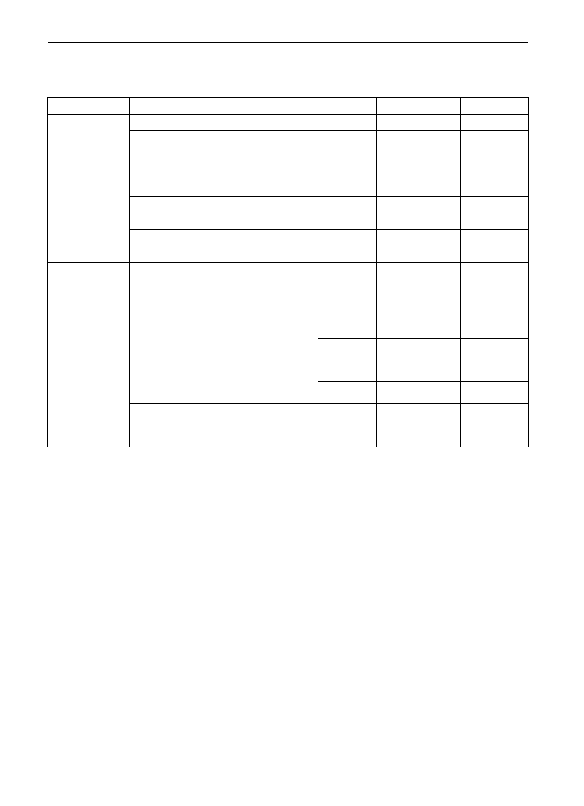
Tightening Torque
Fastening Location Torque (Kg.M)
Generator and Ignition System
Fastening bolt of AC generator 2.4
Stay bolt 2.4
Pivot nut 2.3
Crankshaft pulley bolt 2.5
Spark plug 2.5
Ignition coil bolt 1.1
Timing toothed-belt
Lower front cover of timing toothed-belt 1.1
Tensioning pulley bolt 4.9
Tensioning wheel arm bolt 2.2
Automatic tensioning wheel bolt 2.4
Central pulley bolt 3.6
Tensioning wheel bracket 4.9
Rear cover of timing toothed-belt 1.1
Timing belt indicator 0.9
Toothed-belt wheel of oil pump 5.5
Crankshaft toothed-belt wheel bolt 12.0
Tensioner B 1.9
Toothed-belt wheel of balancing shaft 4.6
Camshaft toothed-belt wheel bolt 9.0
Toothed-belt wheel of balancing shaft 4.6
Fuel System
Throttle 1.9
Fuel distributing pipe assembly 1.2
Intake manifold
Eye bolt of engine 1.9
Cooling water temperature sensor plug of engine 3.0
Water outlet port coupling bolt 2.0
Intake manifold bolt 2.0
Water temperature sensor 3.0
Exhaust manifold
Exhaust manifold cover bolt 1.4
Water inlet port coupling bolt 2.4
Exhaust manifold nut (M8) 3.0
Exhaust manifold nut (M10) 5.0
Cooling water bypass pipe connector bolt 2.4
Cooling water pipe assembly bolt 1.3
Thermostat shell bolt 2.4
Water pump bolt 1.4
Rocker Arm and Camshaft
Rocker cover bolt 0.4
Rocker arm and camshaft assembly bolt 3.2
Thrust cover screw 1.9
Cylinder head and valve
Cylinder head bolt 2.0 90 90
11-5
11-6
Fastening Location Torque (Kg.M)
Front cover and oil pump
Oil drain plug 4.5
Oil pan 0.7
Oil suction filter bolt and nut 1.9
Oil pressure switch 1.0
Pressure relief plug 4.5
Oil suction filter bracket bolt 1.9
Front cover bolt 2.4
Plug 2.4
Flange bolt 3.7
Oil pump cover bolt 1.6
Oil pump cover screw 1.0
Piston and connecting rod assembly
Connecting rod nut 2.0 90100
Crankshaft, cylinder block, flywheel and drive board
Flywheel bolt 13.5
Rear cover board mounting bolt 1.1
Oil-seal retainer mounting bolt 1.1
Main bearing cap bolt 2.5 90100
ENGINE SPECIFICATION
A New Tightening Method Bolt Tightening at Plasticity Area
A new tightening method bolt tightening at plasticity area will be used in some parts of engine. Different from
traditional tightening method, the use limit stated herein shall be followed while tightening the bolts.
This method shall be applied to the following bolts:
(1) Cylinder head bolt
(2) Main bearing cap bolt
(3) Connecting rod bolt
Tightening method:
Screw the bolt till the prescribed torque is reached, then tighten another 90100(for cylinder head bolt, 2 90
is needed). When the area is different, the method is also different. The methods stated herein shall be followed.
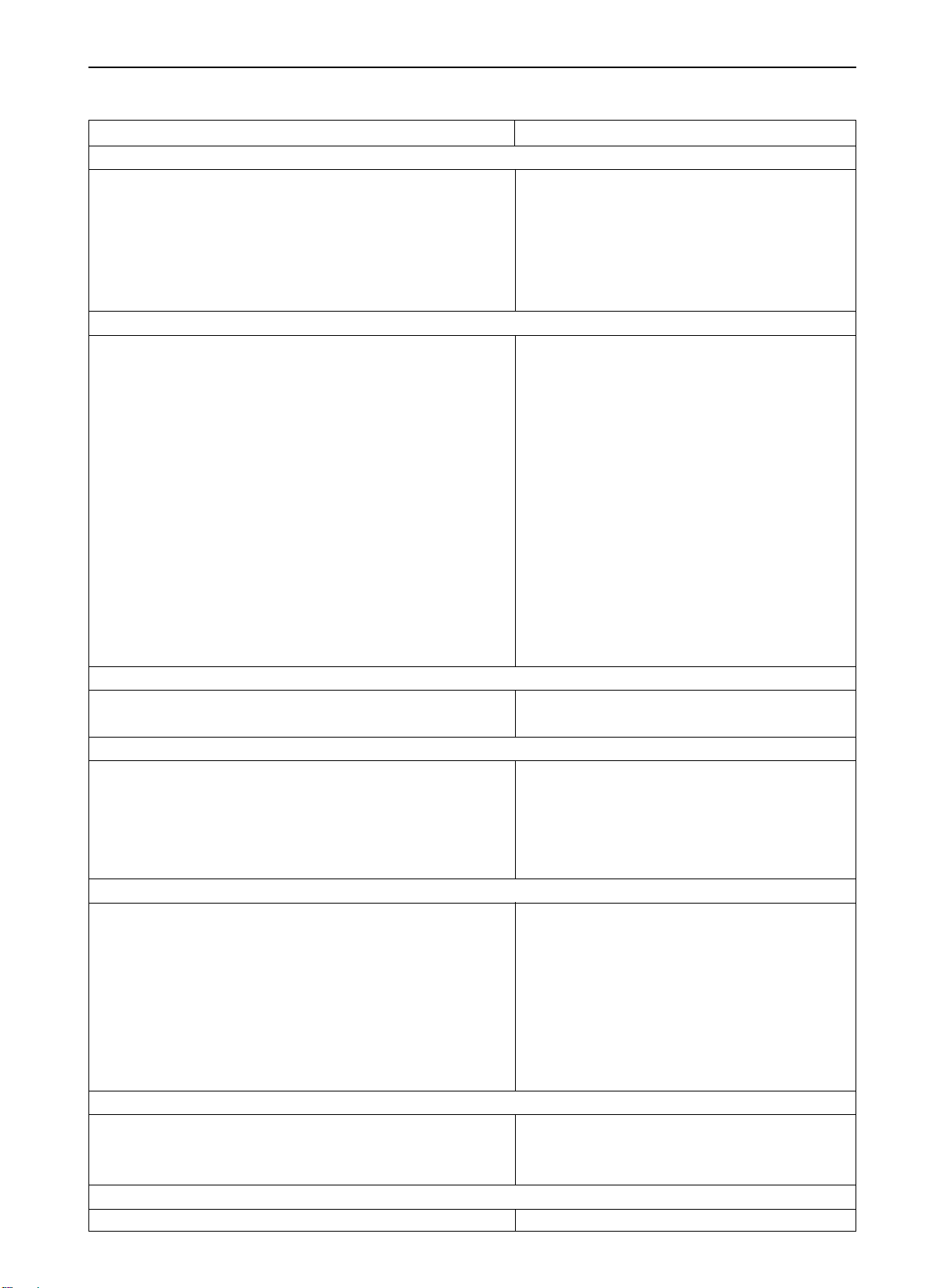
Sealant
Applying Location Model to Use
Water outlet port coupling MD970389 or the equivalent
Cooling water bypass pipe connector MD970389 or the equivalent
Oil pressure switch 3M ATD No.8660 or the equivalent
Oil pan MD970389 or the equivalent
Oil-seal retainer MD970389 or the equivalent
Water temperature sensor 3M NUT LOCKING No.4171 or the equivalent
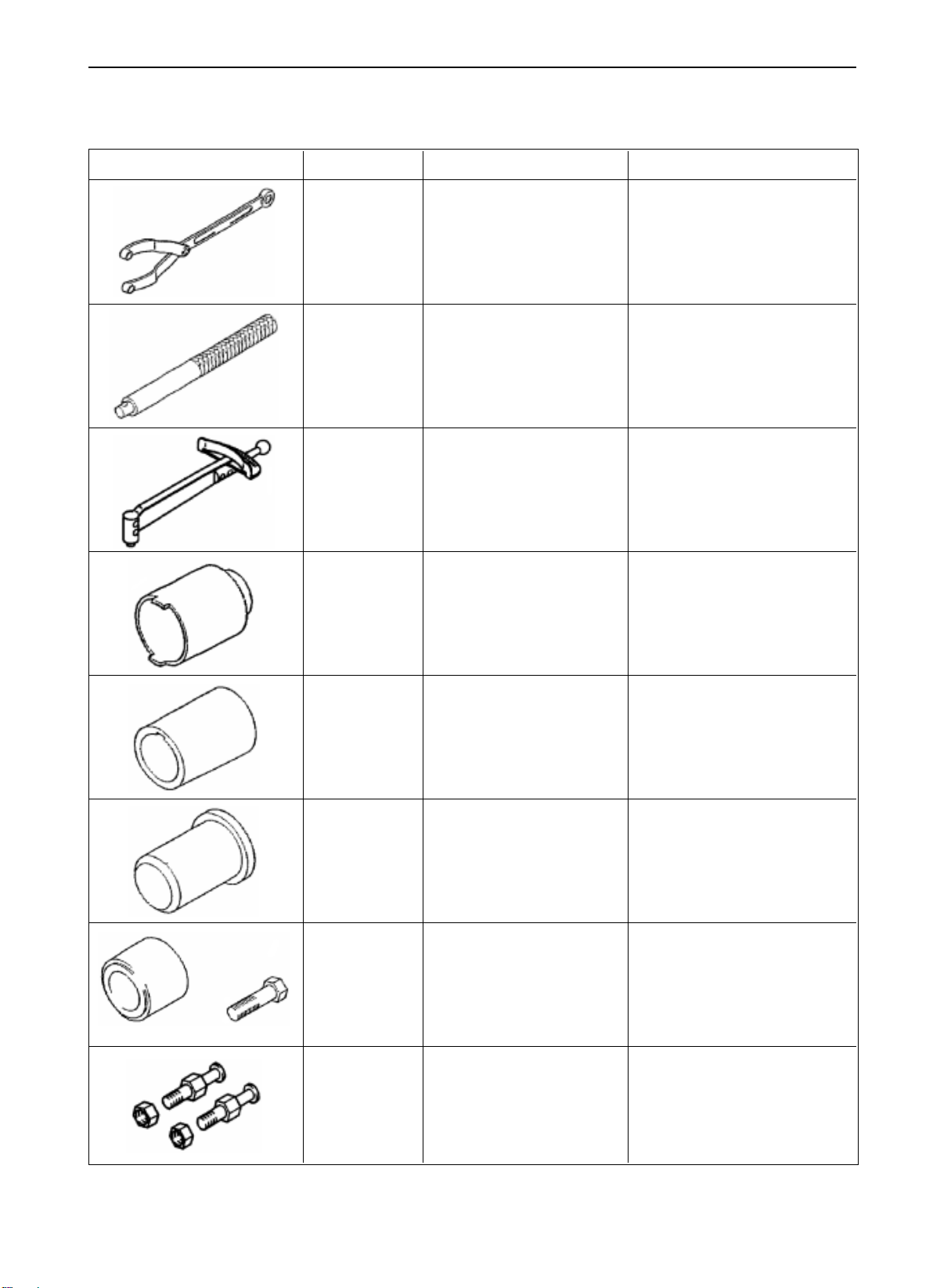
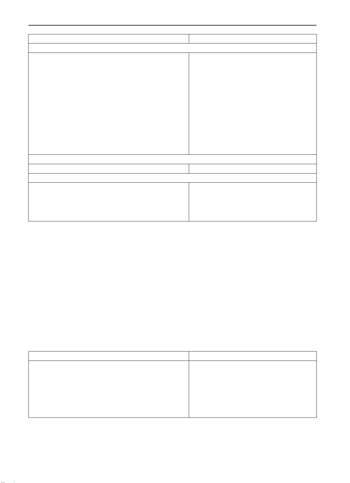
SPECIAL TOOLS
Tools REF. NO. NAME PURPOSE
ENGINE SPECIAL TOOLS
11-7
MB990767
MB990938 HANDLE Use together with MD998776
MD990685 TORQUE WRENCH
MD998162
CRANKSHAFT PULLEY
WRENCH
SCREW-PLUG
WRENCH
Use MD998719 for Fastening
camshaft toothed-belt wheel
Use MD998767 for timing
toothed-belt tensioning
Disassembly and mounting of
front cover plug
CRANKSHAFT FRONT
MD998285
MD998375
MD998713 Mounting of camshaft oil seal
MD998719 PULLEY FIXING PIN
OIL SEAL GUIDE
CRANKSHAFT FRONT
OIL SEAL ASSEMBLER
CAMSHAFT OIL SEAL
ASSEMBLER
Use MD998375 for mounting of
crankshaft front oil seal
Mounting of crankshaft front
oil seal
Use MB990767 for the fastening
of camshaft toothed-belt wheel
11-8
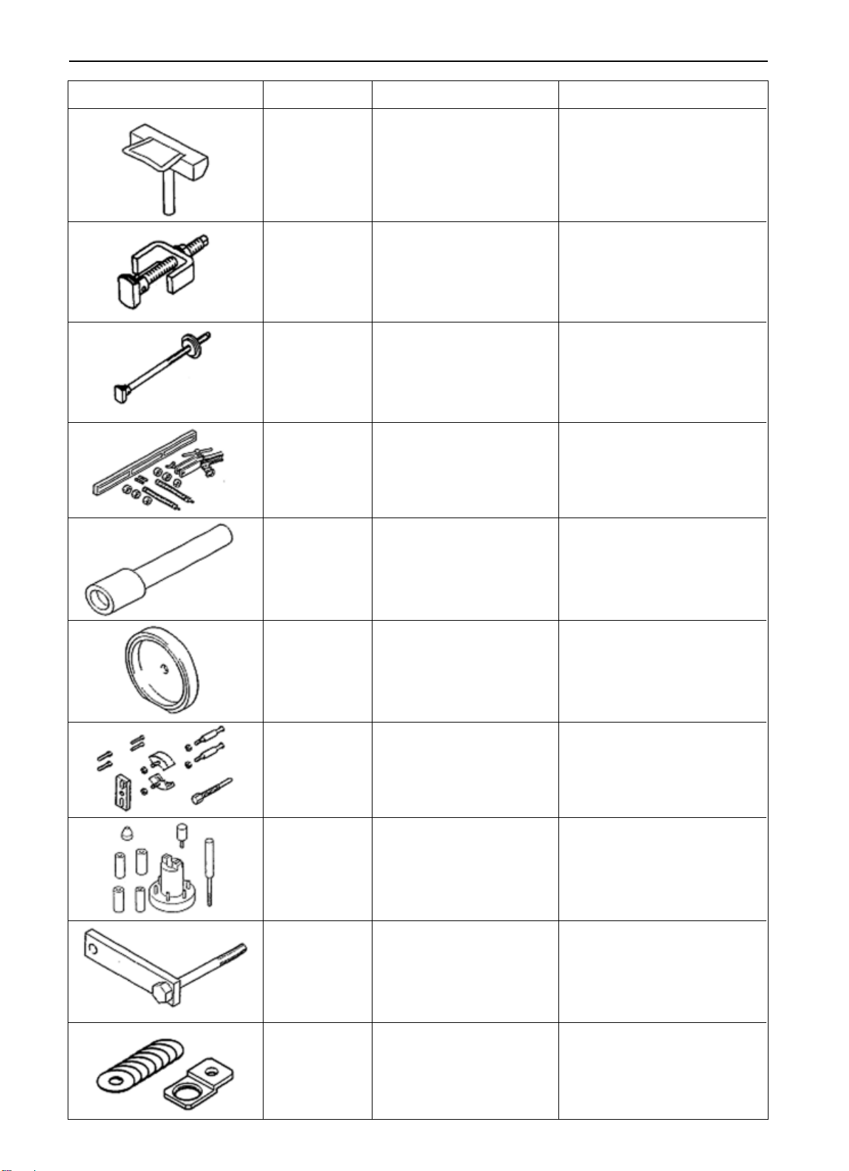
ENGINE SPECIAL TOOLS
Tools REF. NO. NAME PURPOSE
MD998727 OIL PAN DETACHER Disassembly of oil pan
MD998371
MD998372
MD998772 VALVE SPRING
MD998774 Mounting of valve oil seal
MD998776
BALANCING SHAFT
BEARING PULLER
BALANCING SHAFT
BEARING PULLER
VALVE OIL SEAL
ASSEMBLER
CRANKSHAFT REAR
OIL SEAL ASSEMBLER
Disassembly of reverse balancing shaft front bearing
Disassembly of reverse balancing shaft rear bearing
Disassembly and mounting of
valve and related spare parts
Use MB990938 for mounting
of crankshaft rear oil seal
CRANKSHAFT
MD998778
MD998780 Disassembly of piston pin
MD998781 FLYWHEEL STOPPER
MD998783
TOOTHED-BELT
WHEEL PULLER
PISTON INSTALLATION
TOOL
SCREW-PLUG
WRENCH FIXER
Disassembly of crankshaft
toothed-belt wheel
Fastening flywheel and driving plate
Disassembly and mounting of
front cover screw-plug
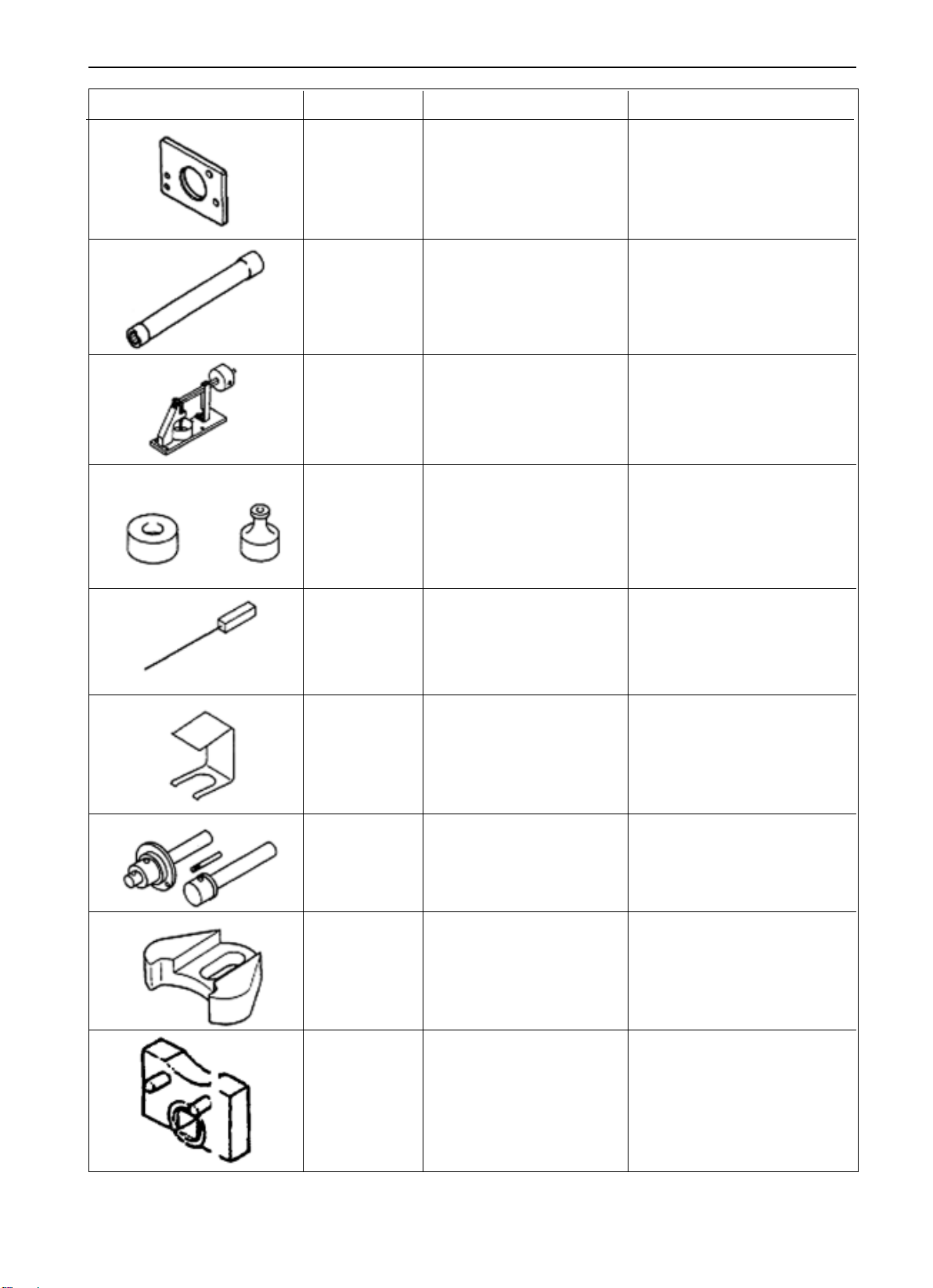
ENGINE SPECIAL TOOLS
Tools REF. NO. NAME PURPOSE
Guide limit for disassembly and
MB991603
BALANCING SHAFT
BEARING PULLER
assembly of reverse balancing
shaft rear bearing (used with
MD998372 together)
11-9
CYLINDER HEAD BOLT
MB991654
MD998440
MD998441
MD998442 Air exhausting of hydraulic lifter
MD998443
WRENCH
LEAKAGE-DETECTING
TESTER
HYDRAULIC LIFTER
RETAINER
HYDRAULIC LIFTER
WIRE
HYDRAULIC LIFTER RETAINER
Disassembly and mounting of
cylinder head bolt
Hydraulic lifter leakage-detect
test
Air exhausting of hydraulic
lifter
Hydraulic lifter retainer while
removing and mounting rocker
shaft assembly
MD998705
MD998785
MD998767 Adjusting tension of timing belt
BALANCING SHAFT
BEARING INSTALLER
TIMING TOOTHED-BELT
STOPPER
TENSIONER PULLING
STEEVE
Mounting of reverse balancing
shaft front & rear bearing
Retaining of balancing shaft
toothed-belt wheel
11-10
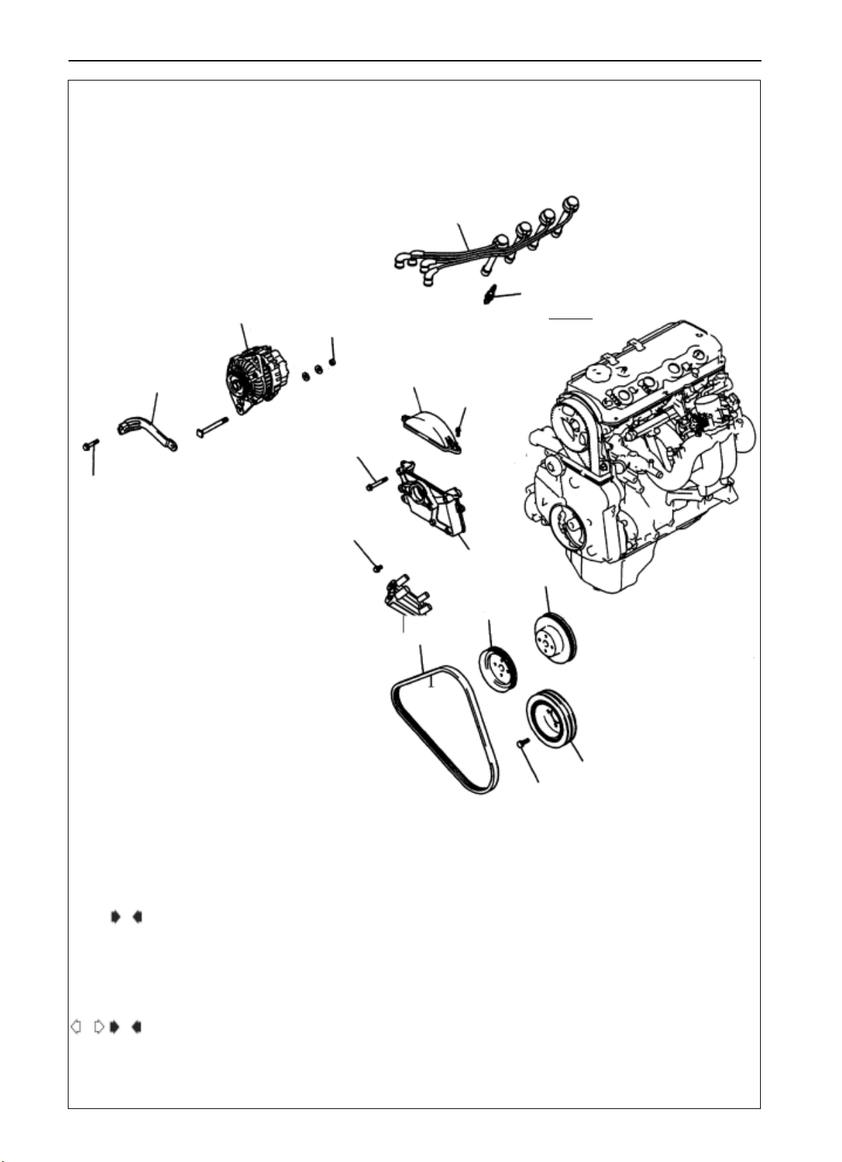
ENGINE AC GENERATOR AND IGNITIONSYSTEM
AC GENERATOR AND
IGNITION SYSTEM
DISASSEMBLY AND MOUNTING
7
23N.m
5
4
23N.m
10
11N.m
9
8
25N.m
11N.m
3
11
9
Disassembly Procedure
1. driving belt
E
2. water pump pulley
3. power steering pump pulley
4. AC generator support
5. AC generator
A D
6. crankshaft pulley
6
25N.m
7. spark plug cable
8. spark plug
9. ignition coll
10. front top cover of timing toothed-belt
11. ignition coil bracket
MD998781
MD998781
ENGINE TIMING TOOTHED-BELT
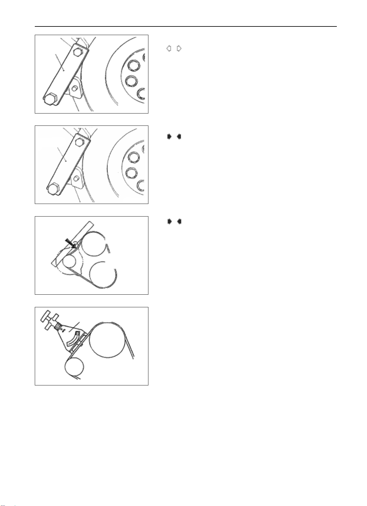
NOTES FOR DISASSEMBLY
A
DISASSEMBLY OF CRANKSHAFT BOLT
(1) Fasten flywheel with special tools
(2) Disassemble crankshaft bolt.
9EN0268
NOTES FOR MOUNTING
D
MOUNTING OF CRANKSHAFT BOLT
(1) Fasten flywheel with special tools.
(2) Mount crankshaft bolt.
11-11
100N
AC generator pulley
9EN0268
water pumo pulley
crankshaf
6EN0595
E
ADJUST DRIVING BELT TENSION TO STANDARD
VALUE WITH DEFLECTION INDICATOR OR
TENSION GAUGE
STANDARD VALUE
NEW BELT ....................................................... 5.57.5mm
OLD BELT ........................................................ 7.58.5mm
STANDARD VALUE
NEW BELT ....................................................... 50 70KG
OLD BELT ........................................................ 35 45KG
6EN0596
11-12
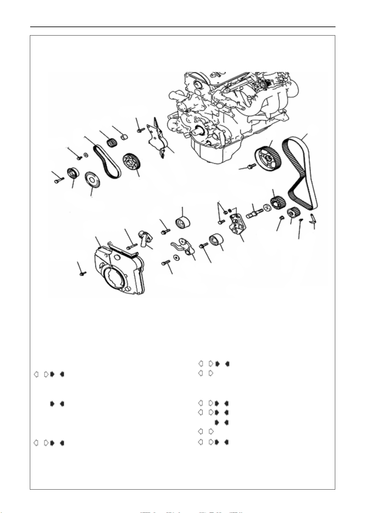
TIMING TOOTHED-BELT
DISASSEMBLY AND MOUNTING
17
16
15
45N
19N
14
13
ENGINE TIMING TOOTHED-BELT
11N.m
8
88N
19
18
48N.
3
20
2
12
162N.m
11
1
11N.m
Disassembly Procudure
1. front lower cover of timing thoothed-belt
2. timing toothed-belt
H
A
3. temsioning pulley
4. tensioning arm
G
5. automatic tensioner
6. centrual pulley
7. tensioning pulley bracket
8. rear cover of timing toothed-belt
9. timing toothed-belt indicator
FB
10. oil pump toothed-bet wheel
24N.
48N.
22N.
4
35N.
C
D
E D
F C
G
H A
10
54N.
7
6
E
11. crakshaft bolt**
8.8N.m
6EN1769
12. crankshaft toothed-belt wheel
13. flange
14. tensioner B
15. timing toothed-belt B
16. balancing shaft toothed-belt wheel
B
17. spacer
18. crankshaft toothed-belt wheel B
19. camshaft toothed-belt bolt
20. camshaft toothed-belt wheel
9

ENGINE TIMING TOOTHED-BELT WHEEL
NOTES FOR DISASSEMBLY
A
DISASSEMBLY OF TIMING TOOTHED-BELT
(1) Record the rotation direction of toothed-belt for correct re-
mounting.
Notes:
Adhering of water or grease to the toothed-belt will sharply
shorten its service life. So, after disassembly, try your best to
6EN0662
avoid the toothed-belt, toothed-belt wheel and tensioner from
being contaminated and adhered by water or grease. No need to
clean these parts. Replace it if it is seriously contaminated.
In case water or grease is found on these parts, check the front cover
oil-seal, camshaft oil-seal and water pump if there exist leakage.
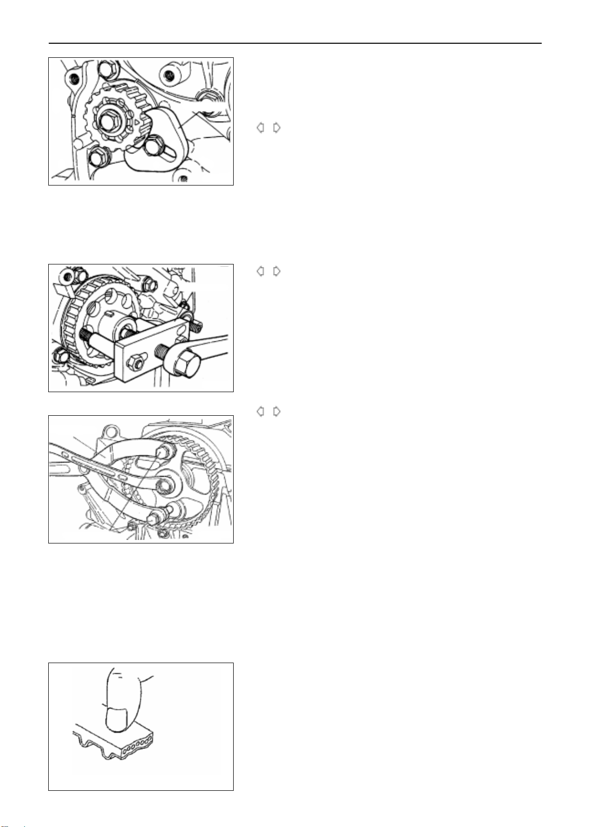
B
DISASSEMBLY OF OIL PUMP TOOTHED-BELT
WHEEL
(1) Assemble the cock on the cylinder block.
(2) Insert a cross point screwdriver of 8mm diameter to fasten
the balancing shaft on the left side.
6EN0663
(3) Disassemble oil pump toothed-belt wheel nut.
(4) Disassemble oil pump toothed-belt wheel.
11-13
MD998781
6EN0634
MD998778
6EN0642
DEN0601
DISASSEMBLY OF CRANKSHAFT BOLT
C
(1) Fasten the flywheel with special tools.
(2) NOTES FOR DISASSEMBLY
DISASSEMBLY OF TIMING TOOTHED-BELT
D
DISASSEMBLY OF CRANKSHAFT TOOTHED-BELT
WHEEL
(1) In case difficult to disassemble due to adhesion, use special
tools.
E
DISASSEMBLY OF TIMING TOOTHED-BELT
WHEEL B
(1) Record the rotation direction of toothed-belt for correct re-
mounting.
Notes:
Adhering of water or grease to the toothed-belt will sharply
shorten its service life. So, after disassembly, try your best to
avoid the toothed-belt, toothed-belt wheel and tensioner from
being contaminated and adhered by water or grease. No need to
clean these parts. Replace it if it is seriously contaminated.
11-14
ENGINE TIMING TOOTHED-BELT WHEEL
In case water or grease is found on these parts, check the front
cover oil-seal, camshaft oil-seal and water pump to see if there
exist leakage.
MD998785
MD990767
6EN0636
MD998778
6EN0637
F
DISASSEMBLY OF BALANCING SHAFT TOOTHED-
BELT WHEEL
(1) Fasten balancing shaft toothed-belt wheel with the tools as
shown in the figure.
(2) Disassemble the balancing shaft toothed-belt wheel.
G
DISASSEMBLY OF CRANKSHAFT TOOTHED-BELT
WHEEL B
(1) In case difficult to disassemble due to adhesion, use special
tools.
H
DISASSEMBLY OF CAMSHAFT TOOTHED-BELT
WHEEL BOLT
(1) Fasten camshaft timing toothed-belt wheel with special tools.
(2) Disassemble camshaft toothed-belt wheel bolt.
MD998719
6EN0668
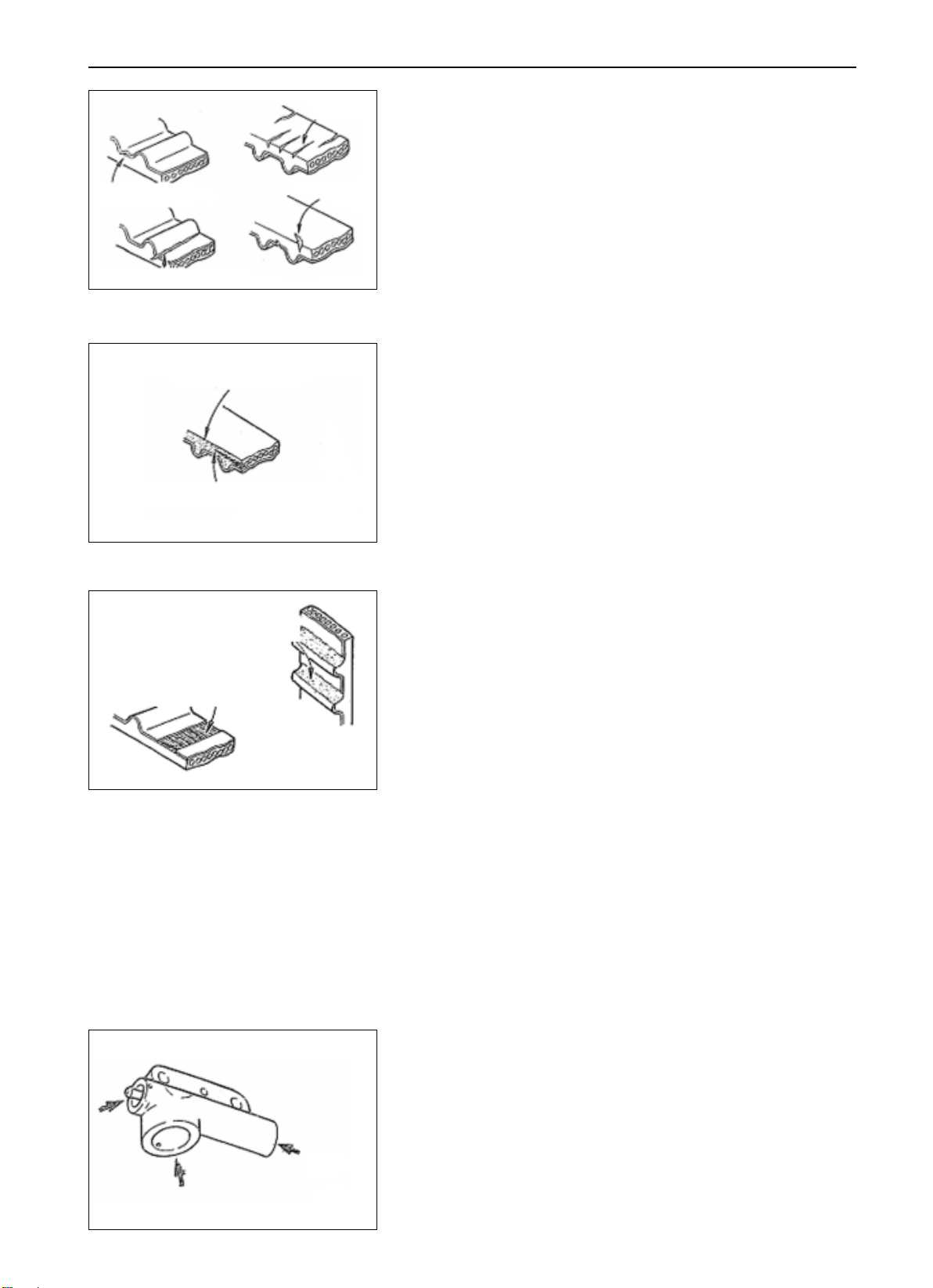
CHECK
TIMING TOOTHED-BELT WHEEL
Carefully check each part of the toothed-belt and replace a new
toothed-belt in case of the following damages:
(1) The back rubber is aged and glistened, no trail left after scraping
with a finger nail, and no elasticity;
8EN0066
ENGINE TIMING TOOTHED-BELT WHEEL
11-15
cracks
canvas peel-off
crack at bottom of tooth
belt margin roueded
abnormal abrasion (heat yarn of belt emposed)
side cracks
1EN0249
8EN0067
(2) There are cracks on the surface of back rubber;
(3) There are cracks and peel-off on the surface of canvas
(4) There are cracks at the bottom of the tooth
(5) There are cracks on the side face of toothed-belt
(6) The side face of toothed-belt is abnormally abraded. The normal
situation is the side face is as level as being cut with a sharp knife
canvas abrased ,rubber exposed
belt teeth broken off
(7) Abnormal abrasion on the tooth surface.
(8) Teeth broken off.
8EN0068
AUTOMATIC TENSIONER
(1) Check automatic tensioner to see if there is leakage and replace
with a new one if necessary.
(2) Check if there is abrasion or damages on the rod end and replace
with a new one if necessary.
6EN0280
 Loading...