

GREAT VIGOR Muscle Car Operating Instructions And Assembly Manual

OPERATING INSTRUCTIONS AND ASSEMBLY MANUAL
®
®

INTRODUCTION
Thank you for selecting this Great Vigor Product.
Please read all instructions and familiarize yourself with the products and controls before
operation. To prevent serious personal injury and/or property damage, operate all controlled
models in a responsible manner as outlined herein. If you come across any problems and
need some help, you can contact us on the internet at www.gv-hobby.com.tw.
We hope you to enjoy our product.
˙ This product is not a toy. It is a high performance model product. It is important to familiarize yourself with the model,
its manual, and its construction before assembly or operation. A child operating under the supervision of the adults is
necessary.
˙ Always keep this instruction manual ready at your hand for your assembling and operating reference, even after
completing the assembly.
˙
˙
CAUTIONS
CHOOSE THE RIGHT PLACE TO OPERATE YOUR R/C MODEL.
˙ Do not operate model products in rain, on public roads, near crowds, near airport, or near areas with restricted radio
operation. This could cause serious accidents, personal injuries, and/or property damage.
˙ Do not run where loud noises can disturb others, such as hospitals and residential areas.
˙ Never run R/C models near people or animals.
˙ Never run indoors. There is a high risk of fire and/or damage.
˙ To avoid injury, do not run in confined spaces.
INSPECT YOUR MODEL BEFORE OPERATION.
˙ For the best performance, it is important to make sure all the moveable parts work free without binding.
˙ Always use fresh batteries for your transmitter and for your receiver to avoid losing control of the model.
˙ Check the radio system and range before every driving session. To properly check the range, have a friend hold the
car with the engine off and walk to the farthest distance that you plan to operate your model. Operate the controls
to make sure the model responds correctly. Do not operate the model if there is any problem with the radio system.
˙ Never share frequency with somebody else at the same time. Radio signals will be mixed and you will lose control of
your model. This may lead to accidents.
˙ Make sure that all screws and nuts are properly tightened. It is also a good idea to use removable thread lock
wherever metal screws go into metal.
˙ Always test the brakes and throttle before starting your engine to avoid losing control of the model.
˙ As the front end of the antenna may be dangerous, do not aim it toward faces.
˙ Never reverse connection/disassemble the battery. This may lead to damage and leakage.
˙ As the product includes small and sharp parts, assemble and store this product only in places out of the reach of
children.
AFTER OPERATION OF YOUR R/C MODEL
˙ Turn off receiver first, then turn off transmitter, this will prevent runaways.
˙ Be sure to keep your R/C model clean and free of excess dirt and grease, this will increase the life.
˙ Be careful when handling batteries, they will be hot after running.
˙ When the model is not in use, always turn off the receiver and transmitter. Furthermore, disconnect the batteries and
remove them from the model and the transmitter. This may be dangerous such as overheat and leakage.
˙ Replace any batteries, they have been dented or have frayed wires, short circuits can cause fire.
˙ Do not store this model in a high-temperature/humidity area or in direct sunlight.
INTRODUCTION
CAUTION
˙
˙
˙ ˙ ˙ ˙ ˙ ˙ ˙ ˙ ˙ ˙ ˙ ˙ ˙ ˙ ˙ ˙ ˙
˙
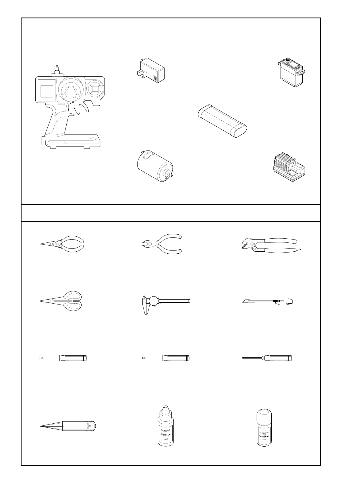
INTRODUCTION
˙2 Channel Radio Set
˙Receiver
˙Steering Servo
˙Battery
˙Motor
˙Electronic Speed Control
CAUTIONS
˙Needlenose Pliers
˙Cutting Pliers
˙Tongue and Groove Pliers
˙Hobby Knife
˙Caliper
˙Body Scissors
˙Screwdriver
˙Screwdriver
˙Hex Wrench
(1.5,2.0,2.5,3.0mm)
˙Diff Silicone oil
˙Shock Oil
˙Body Reamer
EXTRA STUFF NEEDED
ADDITIONAL ITEMS NEEDED FOR OPERATION

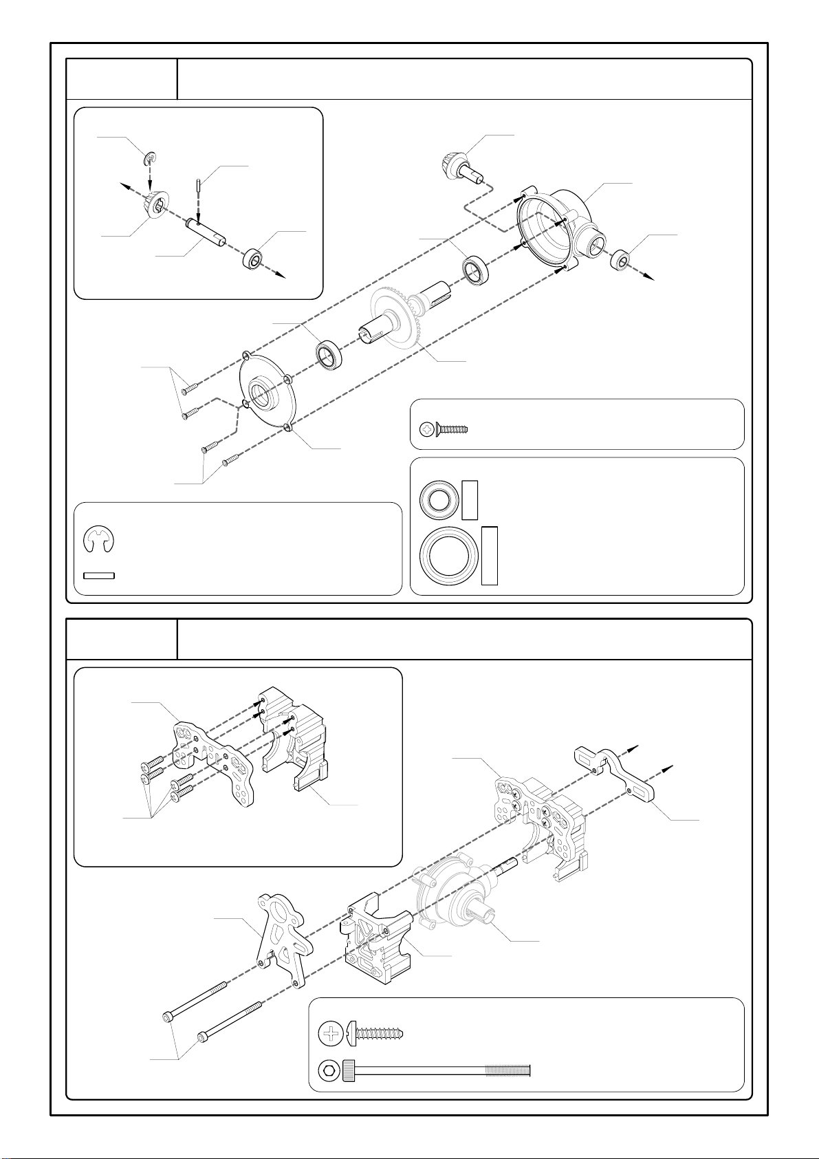
Step 1
Front and Rear Differentials
1A - Washer 2.6x6x1mm -- 4
1B - Washer 12.1x20.5x1mm -- 4
1C - Ball Bearing 5x8x2.5mm -- 2
1E
(EL2292)
1A
EL2285
Differential Oil
EL2287
1B
Differential Oil -- 1
Contain a 2.6mm Lock Nut Inside
For Front and Rear (x2)
EL2292
EL2286
1B1CDifferential Oil
EL2281
(44T)
EL2285
EL2288
1D - Lock Nut 2.6mm -- 2
1E - Cap Screw 2.5x30mm -- 2
Step 2
Front Differential Housing
2A
2B2DEL2290
EL2282
(16T)
<2-1>
Step 2-1
EL2276
2D2EStep 1
2E2C2C
EL2276
2C - F/H Tapping Screw 2x8mm -- 4
2D - Ball Bearing 5x10x4mm -- 2
2E - Ball Bearing 10x15x4mm -- 2
2B - Pin 1.5x7.8mm -- 1
2A - E-Ring 3mm -- 1
Step 3
Rear Differentials Housing
3A
3B3DEL2289
EL2282
(16T)
<3-1>
Step 3-1
EL2276
3D
3E
Step 1
3E3C3C
EL2276
3C - F/H Tapping Screw 2x8mm -- 4
3D - Ball Bearing 5x10x4mm -- 2
3E - Ball Bearing 10x15x4mm -- 2
3B - Pin 1.5x7.8mm -- 1
3A - E-Ring 3mm -- 1
Step 4
Front Shock Tower and Gearbox
EL1322
<4-1>
4A
EL16212
Step 4-1
EL3043RE
Step 2
EL16212
EL3042RE
4B
4B - Cap Screw 3x12mm -- 2
4A - Button Head Tapping Screw 3x12mm -- 4
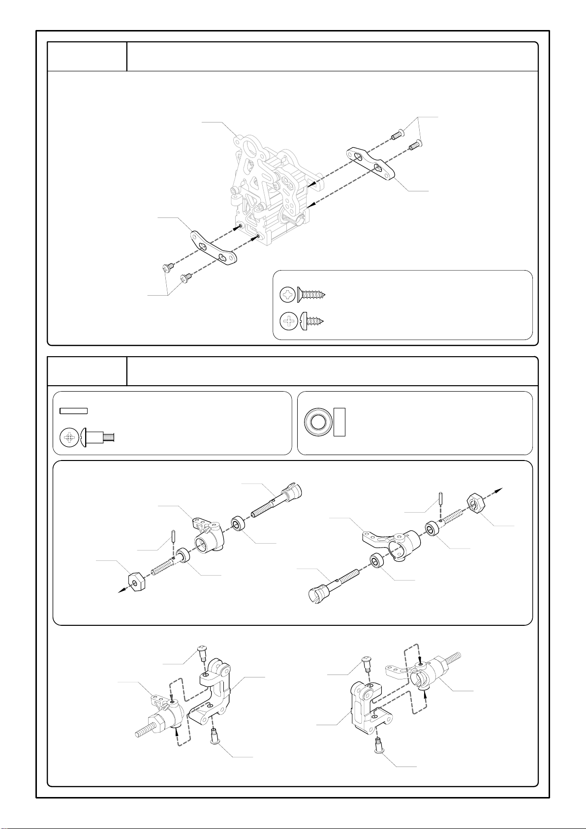
Step 5
Front Suspension Plate and Suspension Plate Holder
5A
EL162D4
Step 4
EL162D2
5B
5A - F/H Tapping Screw 3x10mm -- 2
5B - Button Head Tapping Screw 3x6mm -- 2
Step 6
Front Wheel Shafts and Steering Knuckles
6A - Pin 2x9.8mm -- 2
6B - Rocker Arm Pin 3x10mm -- 4
6C - Ball Bearing 5x10x4mm -- 4
V21071
6A
EL134
V210512L
6C
6C
For Left Side
V210512L
6C6CEL134
For Right Side
6A
V21071
<6-1>
For Right Side
Step 6-1
(R)
6B
(CB353)
V2348
(R)
6B
(CB353)
V2348
(L)
6B
(CB353)
Step 6-1
(L)
For Left Side
6B
(CB353)
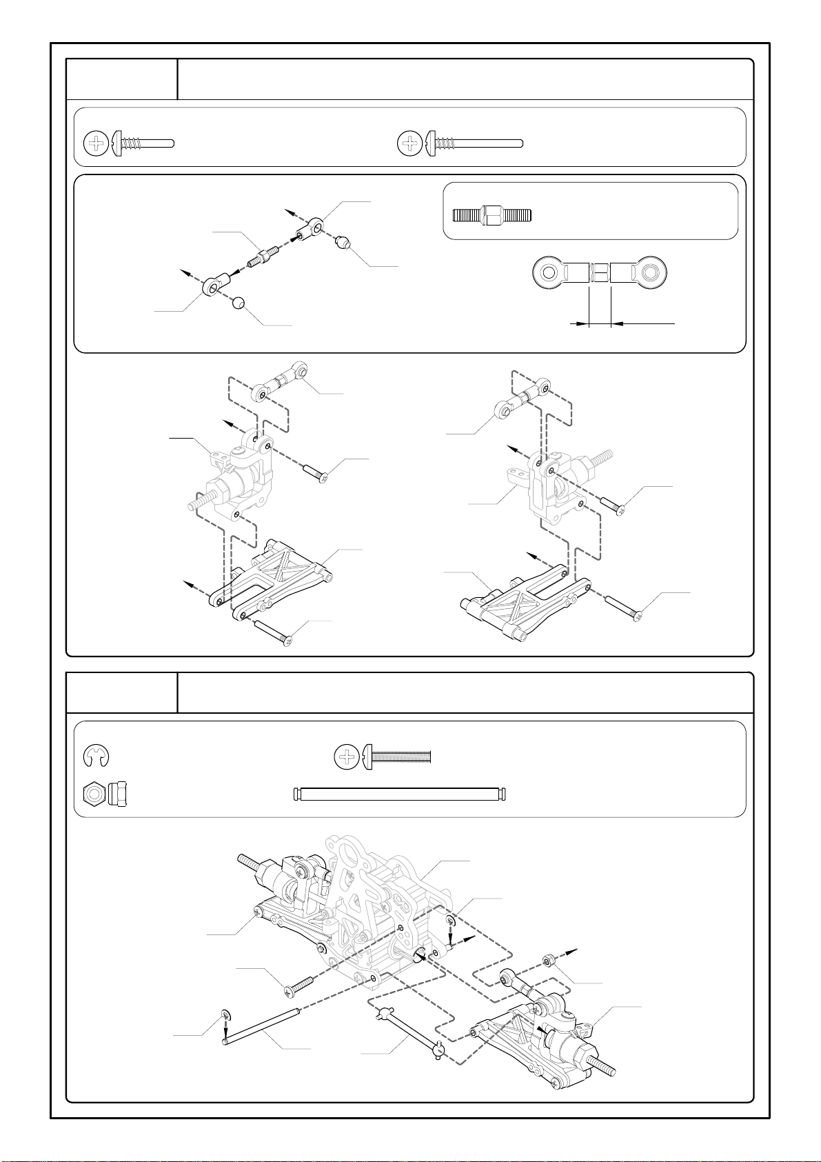
Step 7
Front Upper, Lower Suspension Arms and Wheel Shafts
7A - Hub Stud 3x13.5mm -- 2
7B - Hub Stud 3x22.5mm -- 2
7C - Turnbuckle 5x20mm -- 2
5.6mm
For Right and Left Sides (x2)
V23492
(CB1591)
V23492
(V22151)
<7-1>
7C
(V23492)
V23492
(V22151)
CB113
Step 6
(R)
Step 7-1
(R)
7A
(CB150S)
Step 7-1
(L)
For Left Side
7A
(CB150S)
7B
(CB150A)
EL347F1
Step 6
(L)
EL347F1
7B
(CB150A)
For Right Side
Step 8
Front Suspension
8A - E-Ring 2.5mm -- 4
8B - Lock Nut 3mm -- 2
8C - Button Head Machine Screw 3x15mm -- 2
8D - Hinge Pin 3x54mm -- 2
Step 5
8A
8B
Step 7
(L)
V2355
8D
(EL1111)
8A
8C
Step 7
(R)
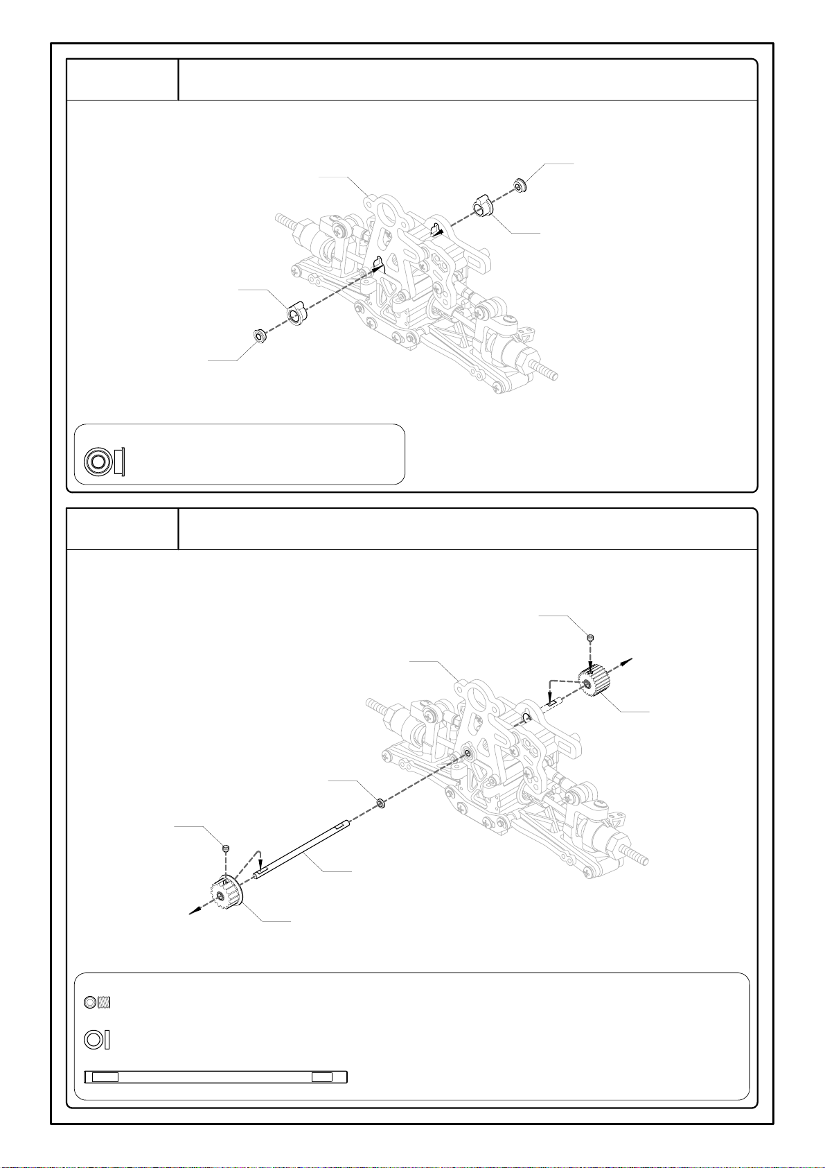
Step 9
Flanged Ball Bearing Mount
Step 8
EL3044
9A
EL3044
9A
9A - Flanged Ball Bearing 3x6x2.5mm -- 2
Step 10
Belt Pulley, Belt Pulley Shaft and Motor Pinion Gear
10A
EL02411HC
(24T)
Step 9
10B
10A
EL228162RE
(16T)
10C
(EL228161)
10C - Belt Pulley Shaft 3x67mm -- 1
10B - Shim 3.2x4.8x1mm -- 1
10A - Grub Screw w/Threadlock 3x3mm -- 2
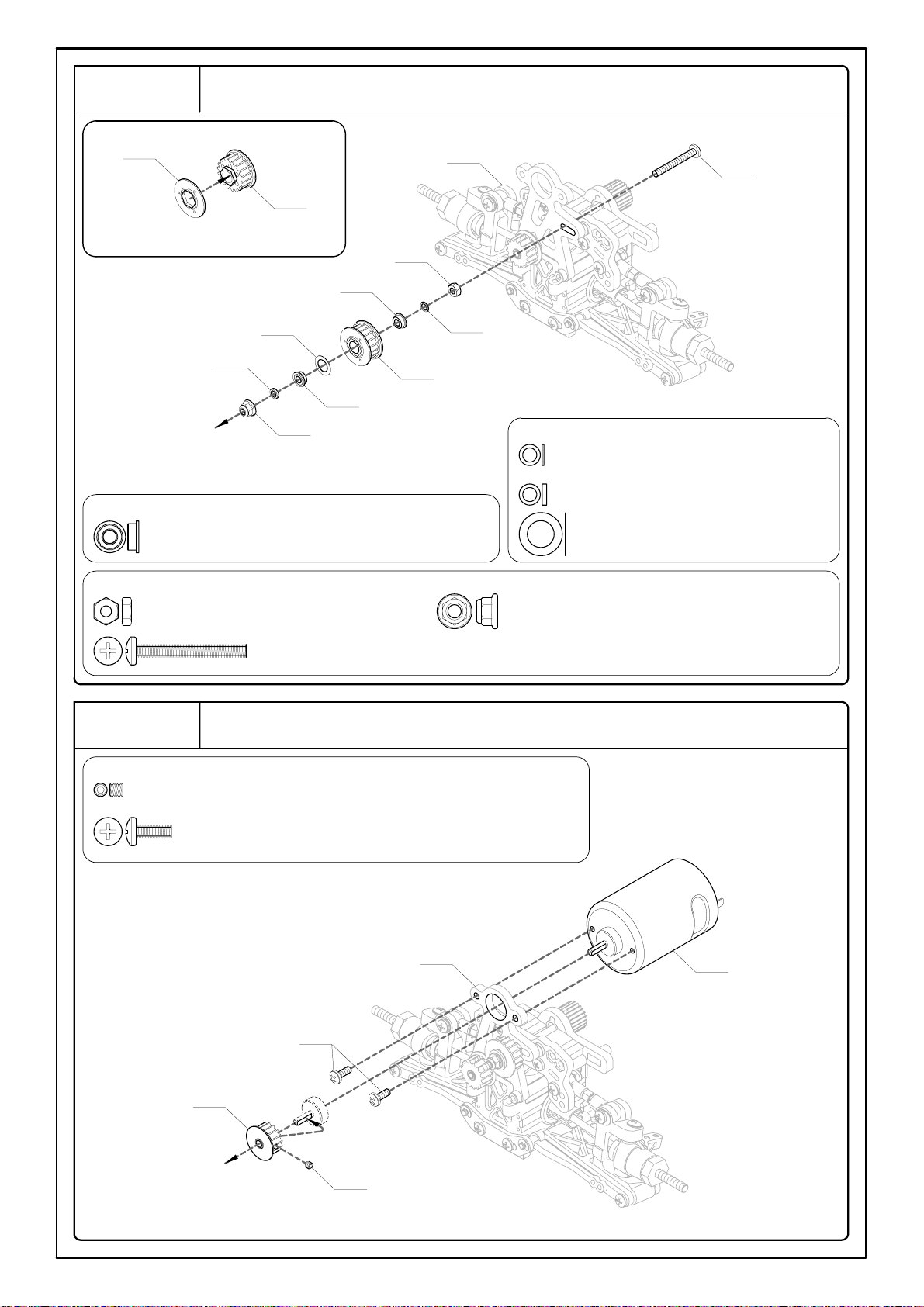
Step 11
Belt Pulley
Step 12
Belt Pulley and Motor
12A - Grub Screw w/Threadlock 3x3mm -- 1
12B - Button Head Machine Screw w/Threadlock 3x8mm -- 2
EL007
Step 11
12B
EL22816RE
(16T)
12A
11G
Step 10
11A
11C
11D
11B
11G - Button Head Machine Screw 3x25mm -- 1
11E - Lock Nut 3mm -- 1
11F - Flange Lock Nut 3mm -- 1
11A - Flanged Ball Bearing 3x6x2.5mm -- 2
11B - Shim 3.2x4.8x0.4mm -- 1
11C - Shim 3.2x4.8x1mm -- 1
11D - Shim 6.1x9.8x0.3mm -- 1
11E
11A
11F
VX22818
(18T)
VX22818
<11-1>
Step 11-1
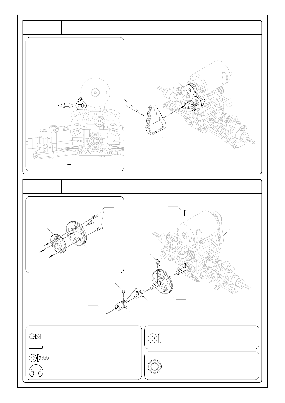
Step 13
Belt Mounting
! This button head machine screw can adjust
belt tension. Move the button head machine
screw to left side to get tighter belt tension
or move the button head machine screw to
right side to get looser belt tension.
Step 11
VX135UK01
Left
Step 14
Main Gear and Main Gear Mount
14C
EL0061
(70T)
<14-1>
EL0061
14B
Step 13
14D
14A
14E
VX103
14F
Step 14-1
14E - O-Ring 3mm -- 1
14F - Ball Bearing 5x10x4mm -- 1
14D - E-Ring 4mm -- 1
14C - F/H Tapping Screw 3x8mm -- 3
14B - Pin 2x9.8mm -- 1
14A - Grub Screw w/Threadlock 4x4mm -- 1
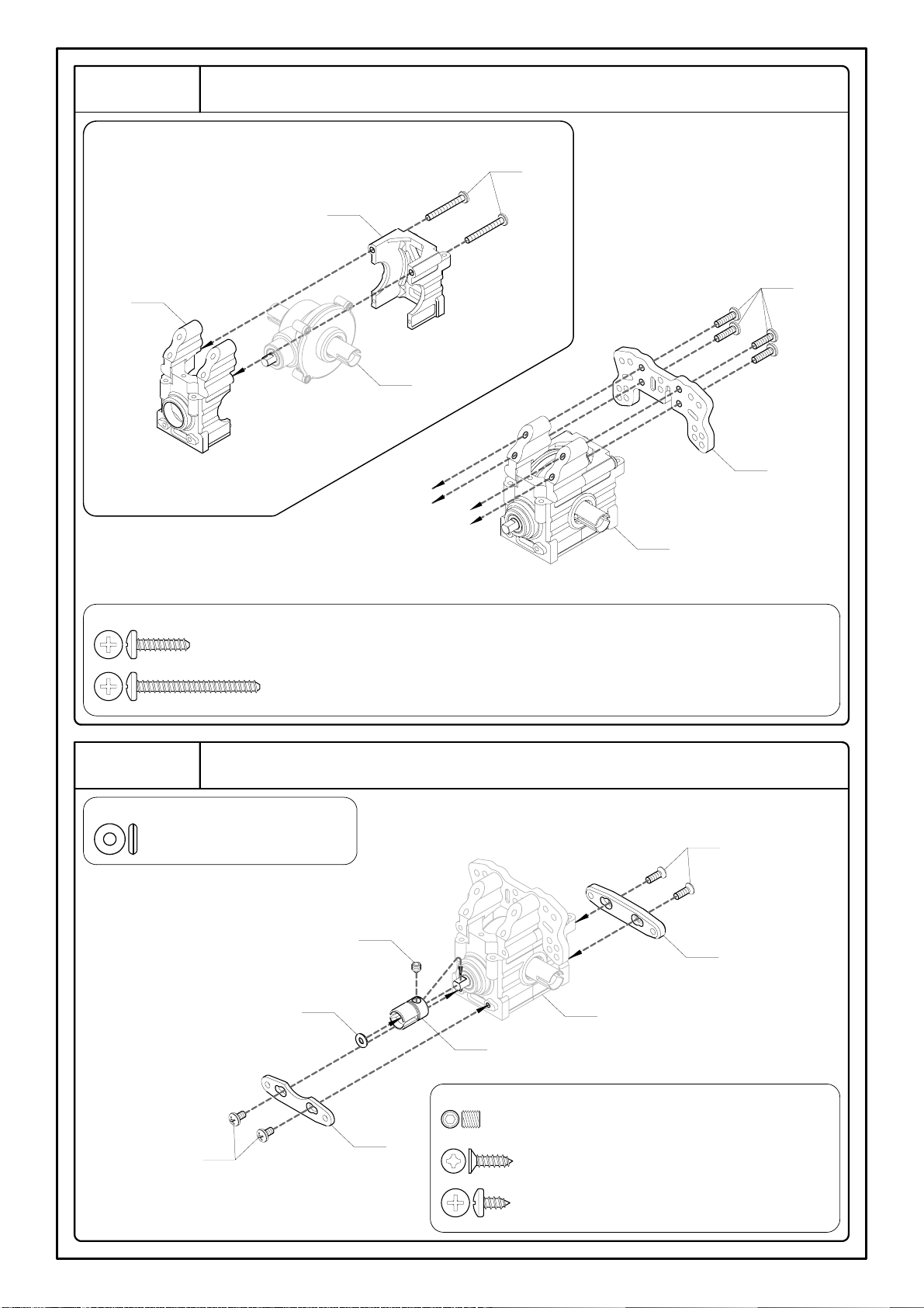
Step 15
Rear Shock Tower and Gearbox
15B
EL16212
Step 3
<15-1>
EL16212
15A
EL1322
Step 15-1
15A - Button Head Tapping Screw 3x12mm -- 4
15B - Button Head Tapping Screw 3x28mm -- 2
Rear Suspension Plate and Suspension Plate Holder
Step 16
16A - O-Ring 3mm -- 1
16C
EL162D4
Step 15
VX103
16B
16A
EL162D3
16D
16B - Grub Screw w/Threadlock 4x4mm -- 1
16C - F/H Tapping Screw 3x10mm -- 2
16D - Button Head Tapping Screw 3x6mm -- 2
 Loading...