

GREAT VIGOR Cage User Manual

INTRODUCTION
Thank you for selecting this Great Vigor Product.
Please read all instructions and familiarize yourself with the products and controls before
operation. To prevent serious personal injury and/or property damage, operate all controlled
models in a responsible manner as outlined herein. If you come across any problems and
need some help, you can contact us on the internet at www.gv-hobby.com.tw.
We hope you to enjoy our product.
˙ This product is not a toy. It is a high performance model product. It is important to familiarize yourself with the model,
its manual, and its construction before assembly or operation. A child operating under the supervision of the adults is
necessary.
˙ Always keep this instruction manual ready at your hand for your assembling and operating reference, even after
completing the assembly.
˙
˙
CAUTIONS
CHOOSE THE RIGHT PLACE TO OPERATE YOUR R/C MODEL.
˙ Do not operate model products in rain, on public roads, near crowds, near airport, or near areas with restricted radio
operation. This could cause serious accidents, personal injuries, and/or property damage.
˙ Do not run where loud noises can disturb others, such as hospitals and residential areas.
˙ Never run R/C models near people or animals.
˙ Never run indoors. There is a high risk of fire and/or damage.
˙ To avoid injury, do not run in confined spaces.
INSPECT YOUR MODEL BEFORE OPERATION.
˙ For the best performance, it is important to make sure all the moveable parts work free without binding.
˙ Always use fresh batteries for your transmitter and for your receiver to avoid losing control of the model.
˙ Check the radio system and range before every driving session. To properly check the range, have a friend hold the
car with the engine off and walk to the farthest distance that you plan to operate your model. Operate the controls
to make sure the model responds correctly. Do not operate the model if there is any problem with the radio system.
˙ Never share frequency with somebody else at the same time. Radio signals will be mixed and you will lose control of
your model. This may lead to accidents.
˙ Make sure that all screws and nuts are properly tightened. It is also a good idea to use removable thread lock
wherever metal screws go into metal.
˙ Always test the brakes and throttle before starting your engine to avoid losing control of the model.
˙ As the front end of the antenna may be dangerous, do not aim it toward faces.
˙ Never reverse connection/disassemble the battery. This may lead to damage and leakage.
˙ As the product includes small and sharp parts, assemble and store this product only in places out of the reach of
children.
AFTER OPERATION OF YOUR R/C MODEL
˙ Turn off receiver first, then turn off transmitter, this will prevent runaways.
˙ Be sure to keep your R/C model clean and free of excess dirt and grease, this will increase the life.
˙ Be careful when handling batteries, they will be hot after running.
˙ When the model is not in use, always turn off the receiver and transmitter. Furthermore, disconnect the batteries and
remove them from the model and the transmitter. This may be dangerous such as overheat and leakage.
˙ Replace any batteries, they have been dented or have frayed wires, short circuits can cause fire.
˙ Do not store this model in a high-temperature/humidity area or in direct sunlight.
INTRODUCTION
CAUTION
˙
˙
˙ ˙ ˙ ˙ ˙ ˙ ˙ ˙ ˙ ˙ ˙ ˙ ˙ ˙ ˙ ˙ ˙
˙
1
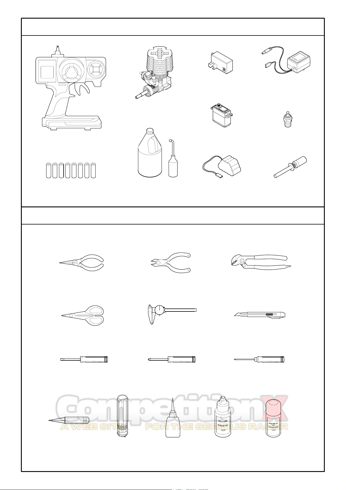
˙Body Reamer
˙Shock Oil
˙Hex Wrench
(1.5,2.0,2.5,3.0mm)
˙Screwdriver (+)
˙Screwdriver (-)
˙Body Scissors
˙Caliper
˙Knife
˙Tongue and Groove Pliers
˙Cutting Pliers
˙Needlenose Pliers
˙Um-3 Battery (8 Pcs)
˙2 Channel Radio Set
˙Fuel&Fuel Pump
˙Battery
˙Glow Plug Igniter
˙Plug
˙Servo
˙Engine
˙Receiver
˙Tx/Rx Charger
EXTRA STUFF NEEDED
CAUTIONS
INTRODUCTION
(Included with RTR version)
(Purchase separately)
(Included with RTR version)
(Included with RTR version)
(Included with RTR version)
(Included with RTR version)
(Purchase separately)
(Purchase separately)
(Purchase separately)
(Purchase separately)
(Purchase separately)
˙Tyre Glue
˙Clutch Tool
2
˙Differential Silicone oil
EXTRA STUFF NEEDED TO MAINTAIN YOUR BUGGY
ADDITIONAL ITEMS NEEDED FOR OPERATION
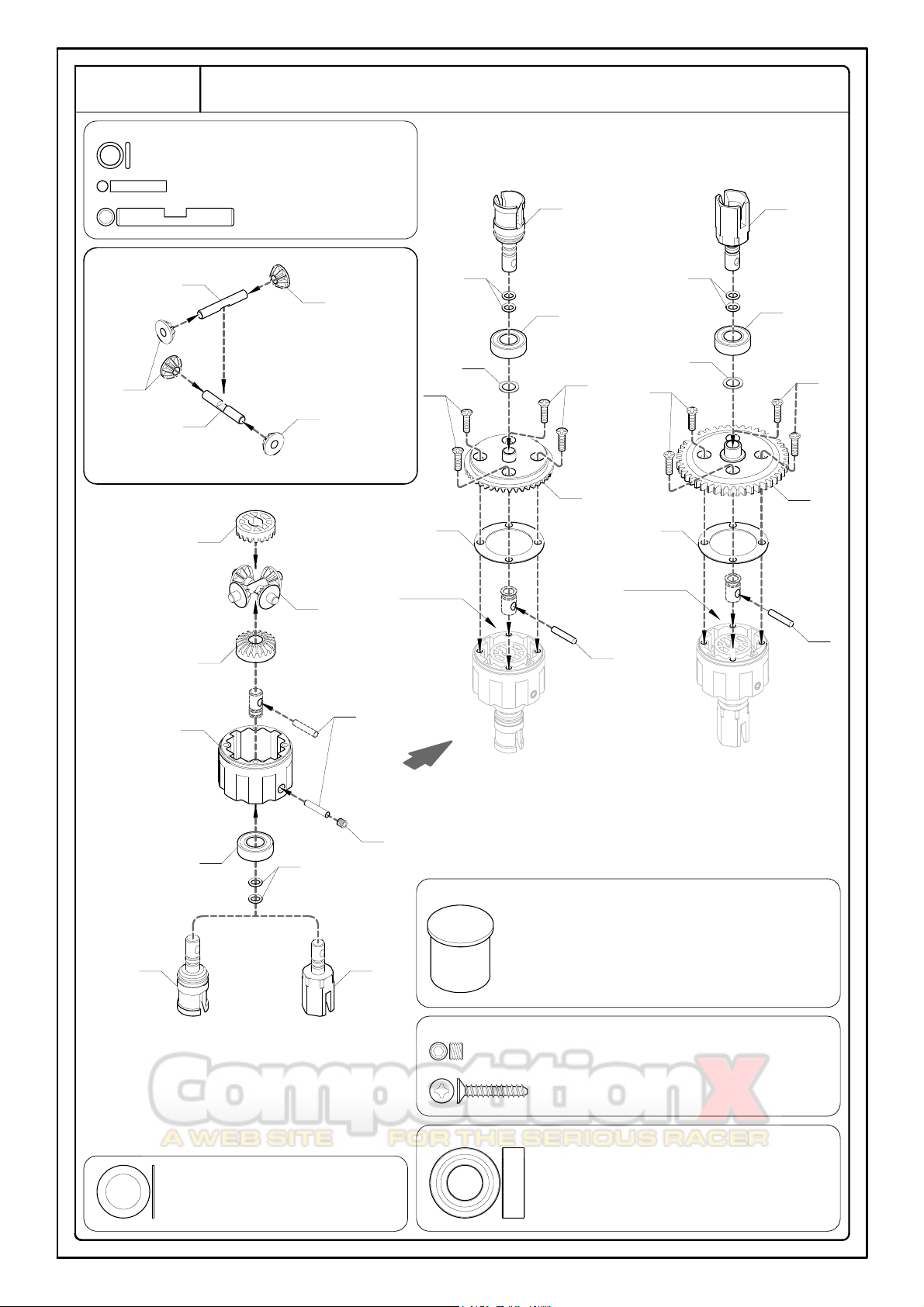
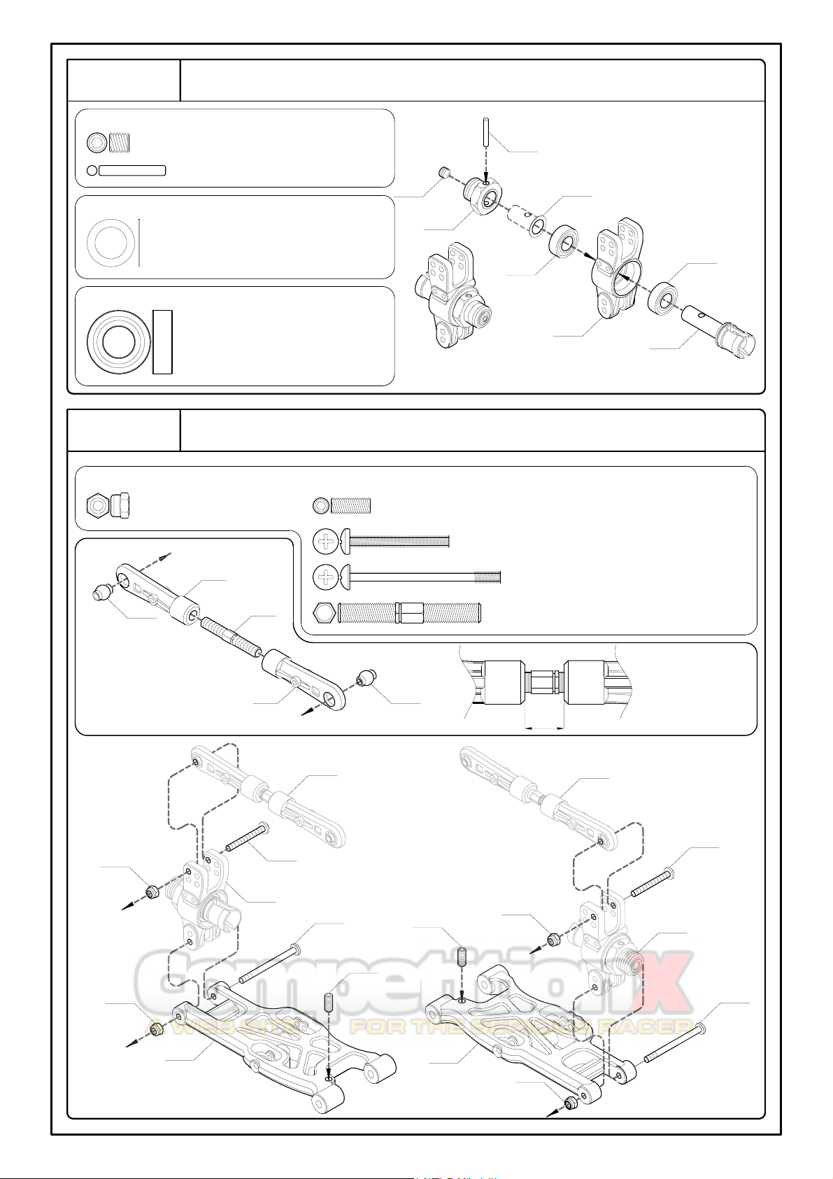
Step 1
Front, Rear and Centre Differentials
1A - O-Ring 3x1mm -- 12
1B - Pin 2.5x12.8mm -- 6
1C - Pin 4x26.6mm -- 6
1C
MV22873
MV22873
1C
MV22873
<1-1>
MV22873
MV22873
Step 1-1
1B
1E1GMV22873
MV11721
MV11711
For Centre (x1)
For Front and Rear (x2)
For Front and Rear (x2)
For Centre (x1)
Differential Oil -- 1
1E - Grub Screw 4x3mm -- 3
1F - F/H Tapping Screw 3x16mm -- 12
1G - Ball Bearing 8x16x5mm -- 6
1D - Shim 8x12x0.4mm -- 3
1B
Differential
Oil
MV22873
1F1D1A
MV11721
1G
1F
MV22811
(43T)
MV11711
1A1G1D
1F
1F
MV22832
(48T)
MV22873
Differential
Oil
1B
1A
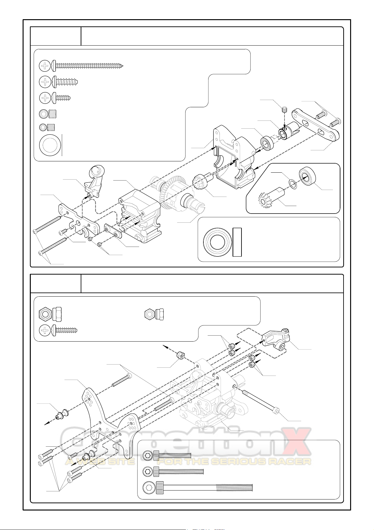
2B
2A - Button Head Tapping Screw 3x38mm -- 2
2D - Grub Screw w/Threadlock 5x4mm -- 1
Front Gearbox
Step 2
<2-1>
MV22821
(13T)
2F - Shim 8x12x0.4mm -- 1
2G - Ball Bearing 8x16x5mm -- 2
3B - Button Head Tapping Screw 3x12mm -- 1
2B - Button Head Tapping Screw 4x12mm -- 2
2G
2F
MV162D4
MV1173
2G
XV1631
Step 2-1
Step 1
XV1631
XV1657
2C
XV162U1AL
2A
2D
Front Shock Tower and Chassis Brace
Step 3
2C - Button Head Tapping Screw 3x10mm -- 1
3C - Lock Nut 3mm -- 4
3A - Lock Nut 4mm -- 1
XV1625F1
3C3C3A
MV110
MV110
3B
3D3FStep 2
3E
XV1321AL
3F - Cap Screw 4x50mm -- 1
3D - Cap Screw 3x18mm -- 4
3E - Cap Screw 3x25mm -- 2
2E - Grub Screw 4x4mm -- 1
MV3618F
(XV3611)
2E
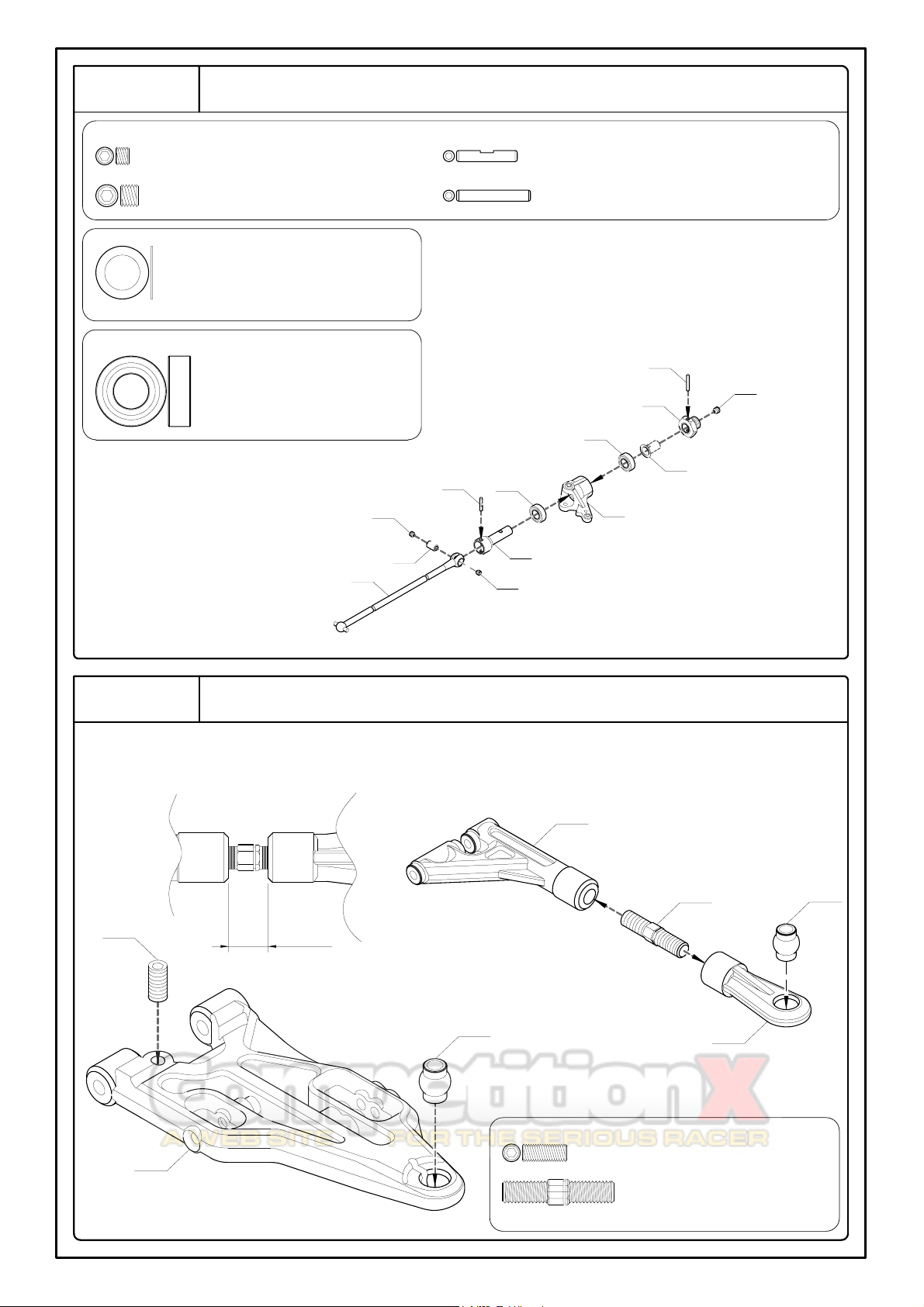
4A - Grub Screw w/Threadlock 4x3mm -- 4
4B - Grub Screw w/Threadlock 5x5mm -- 2
4C - Pin 2.5x13.8mm -- 2
4D - Pin 2.5x16.8mm -- 2
4E - Shim 8x12x0.2mm -- 2
4F - Ball Bearing 8x16x5mm -- 4
4D
MV107
4B4E4F
MV134
4F
4C4AMV3574
MV3575
4A
MV3575
For Right and Left Sides
Front Suspension
Step 4
Step 5
Front Upper Arm
5A - Grub Screw 4x10mm -- 2
5B - Turnbuckle 5x25mm -- 2
XV11304
5B
(MV3491)
XV347F1
(R)
XV349F1
8.8mm
5A
For Right and Left Sides
XV349F1
XV11304
For Right and Left Sides
Step 4
6A
XV13401
Step 5
For Left Side
6A - Button Head Machine Screw w/Threadlock 4x20 mm -- 4
For Right Side
Step 5
Step 5
Step 5
Step 4
6A
6A6AXV13401
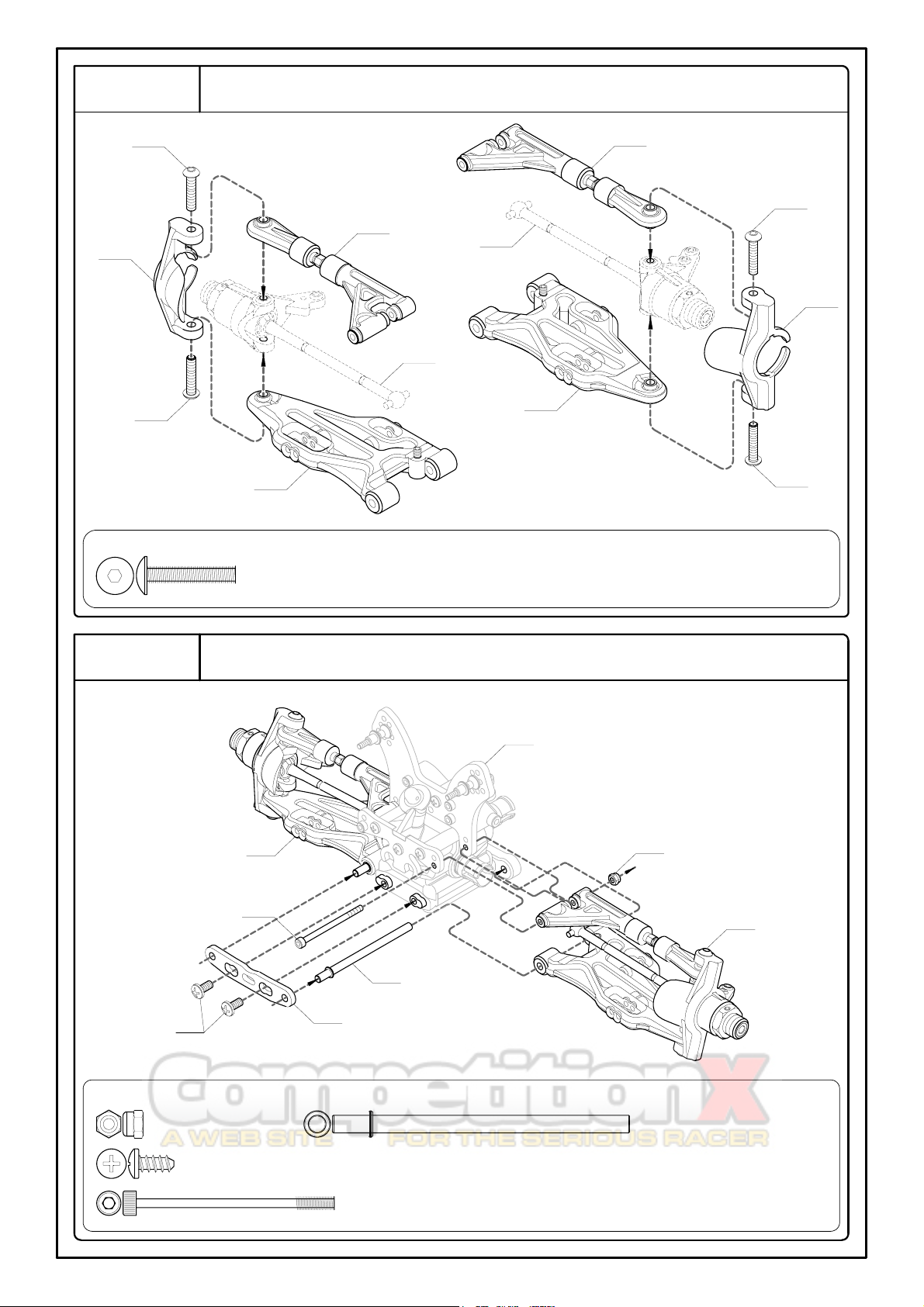
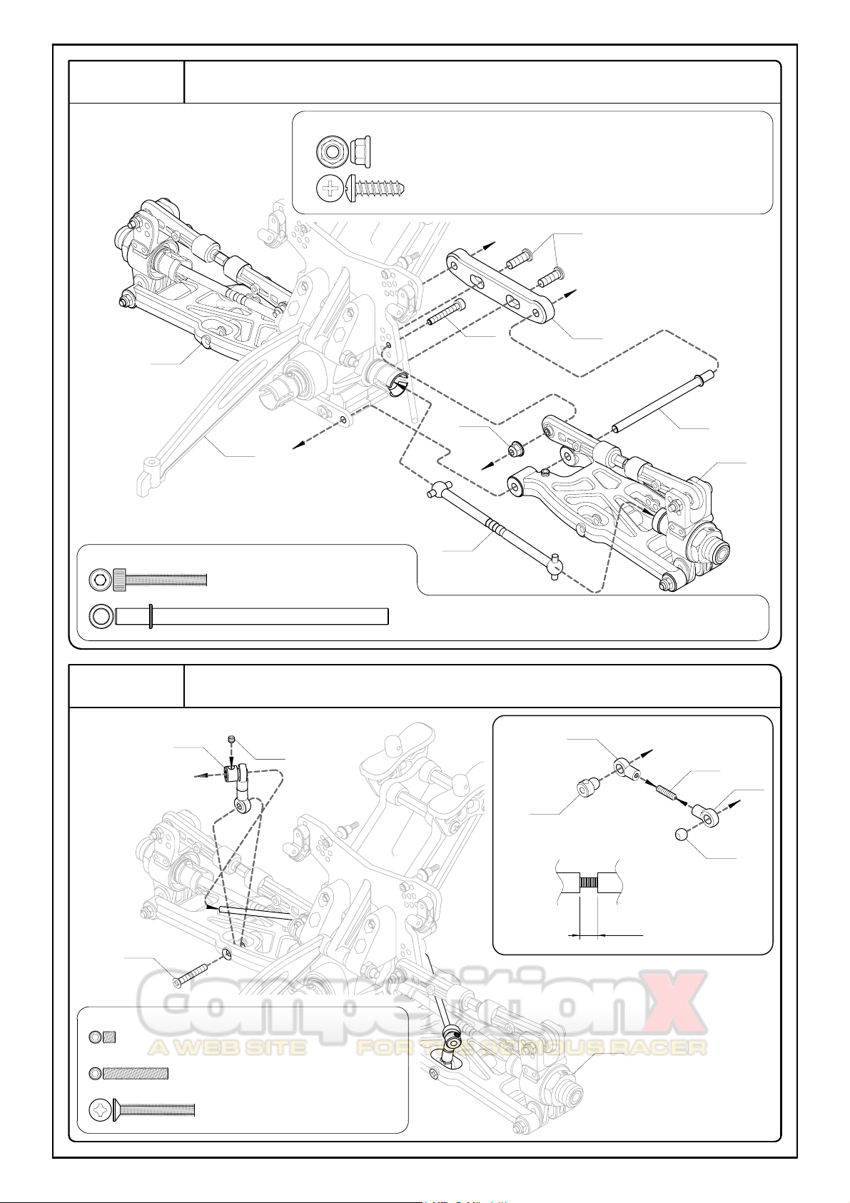
Step 6
Front Upper Arm
Step 7
Front Suspension
7D
(MV11101)
Step 6
(L)
7B
Step 3
Step 6
(R)
7C
7D - Hinge Pin 4x67.5mm -- 2
7C - Cap Screw 3x45mm -- 2
MV162D5AL
7A - Lock Nut 3mm -- 2
7B -- Button Head Tapping Screw 4x8mm -- 2
7A
8A
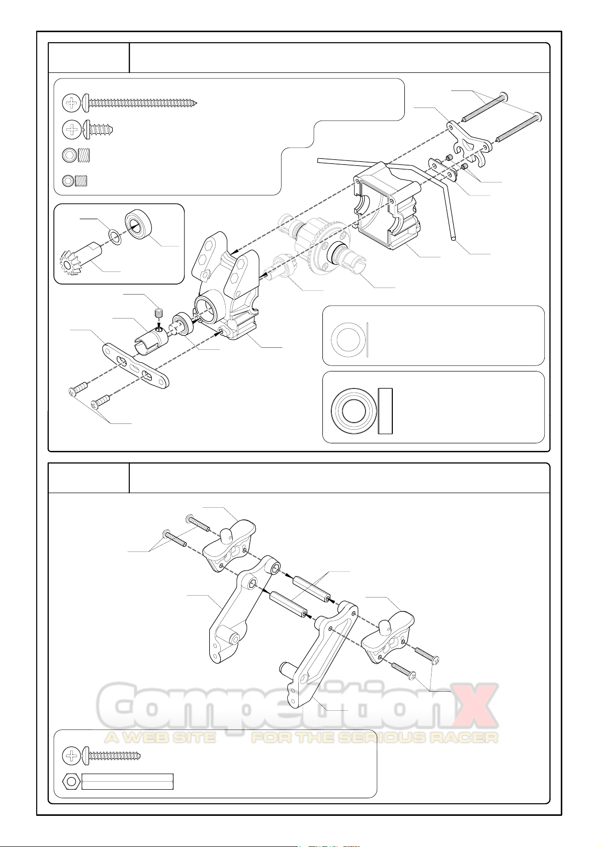
8A - Button Head Tapping Screw 3x38mm -- 2
8C - Grub Screw w/Threadlock 5x4mm -- 1
Rear Gearbox
Step 8
<8-1>
MV22821
(13T)
8F - Ball Bearing 8x16x5mm -- 2
8E - Shim 8x12x0.4mm -- 1
8B - Button Head Tapping Screw 4x8mm -- 2
8E
8F
XV162U2AL
XV1631
Step 8-1
Step 1
8F
XV1631
8C
XV162U1AL
8B8DMV1173
8D - Grub Screw 4x4mm -- 2
XV3613
XV3613
Wing Mount
9A
MV1412
9B
(MV1412)
MV1412
MV1412
MV1412
9A
9B - Post 6x32mm -- 2
9A - Button Head Tapping Screw 3x18mm -- 4
Step 9
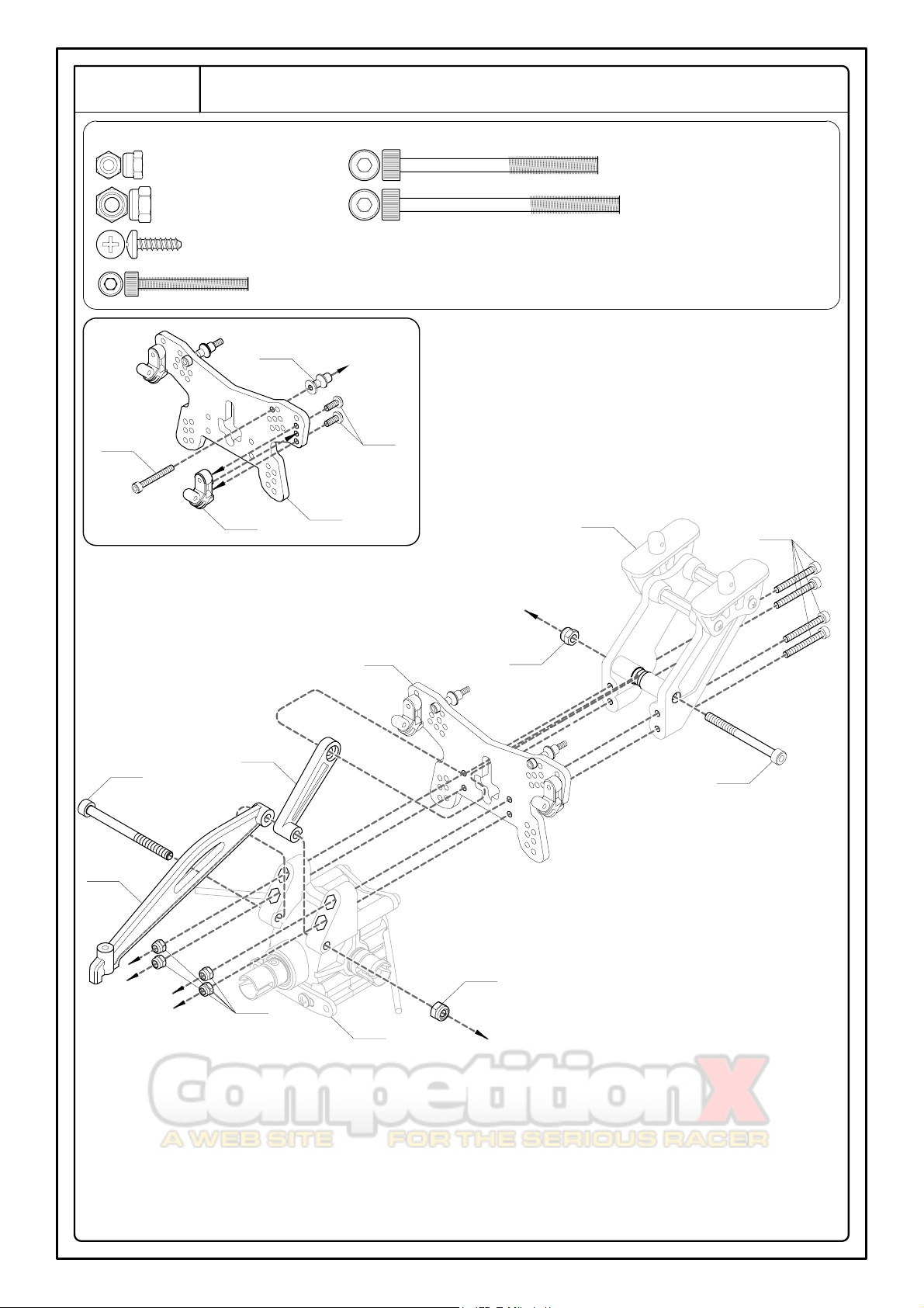
Rear Shock Tower
10A - Lock Nut 3mm -- 4
10B - Lock Nut 4mm -- 1
10C - Button Head Tapping Screw 3x10mm -- 2
10E - Cap Screw 4x45mm -- 1
10D - Cap Screw 3x25mm -- 6
10D
Step 9
10B
Step 10-1
10E
MV1411
10D
MV1671
Step 8
XV1333AL
10C
XV1624R1
<10-1>
Step 10
10D
10B
10B
MV110
10F - Cap Screw 4x50mm -- 1
10F
8
Rear Suspension
11A - Grub Screw w/Threadlock 5x5mm -- 2
11B - Pin 2.5x16.8mm -- 2
11C - Shim 8x12x0.2mm -- 2
11D - Ball Bearing 8x16x5mm -- 4
MV105
11A
MV107
11C
MV3462
11D
11B
11D
Rear Upper Arm
12A - Lock Nut 3mm -- 4
12B - Grub Screw 4x10mm -- 2
12C - Cap Screw 3x25mm -- 2
12D - Hub Stud 3x38mm -- 2
12E - Turnbuckle 5x36mm -- 2
XV349R1
MV113
12E
XV349R1
MV113
10mm
<12-1>
Step 12-1
12A
12C
Step 11
(R)
12A
XV347R1
12B
Step 11
Step 12
For Right and Left Sides
For Right Side
For Left Side
For Left Side
For Right Side
Step 12-1
12C
Step 11
(L)
12A
12B
12A
12D
12D
XV347R1
Rear Suspension
13A - Flanged Lock Nut 3mm -- 2
13C - Cap Screw 3x20mm -- 2
13B - Button Head Tapping Screw 4x12mm -- 2
13D - Hinge Pin 4x67.5mm -- 2
Step 12
(R)
13B
MV162D4
13C
13D
(MV11101)
Step 12
(L)
13A
MV3562
Rear Sway Bar
14A - Grub Screw w/Threadlock 3x3mm -- 2
14B - Grub Screw 3x16mm -- 2
14C- F/H Hex Screw 3x20mm -- 2
14B
4.5mm
XV3613
XV3613
Step 14-1
14A
Step 13
14C
<14-1> (x2)
Step 13
Step 14
Step 10
XV3613
XV3613
10
MV3002RAL
(R)
XV1657
MV3002LAL
(L)
15A
15A
15A
15A
15A
15A
MV1674
MV1674
XV1657
XV1657
MV1674
XV1657
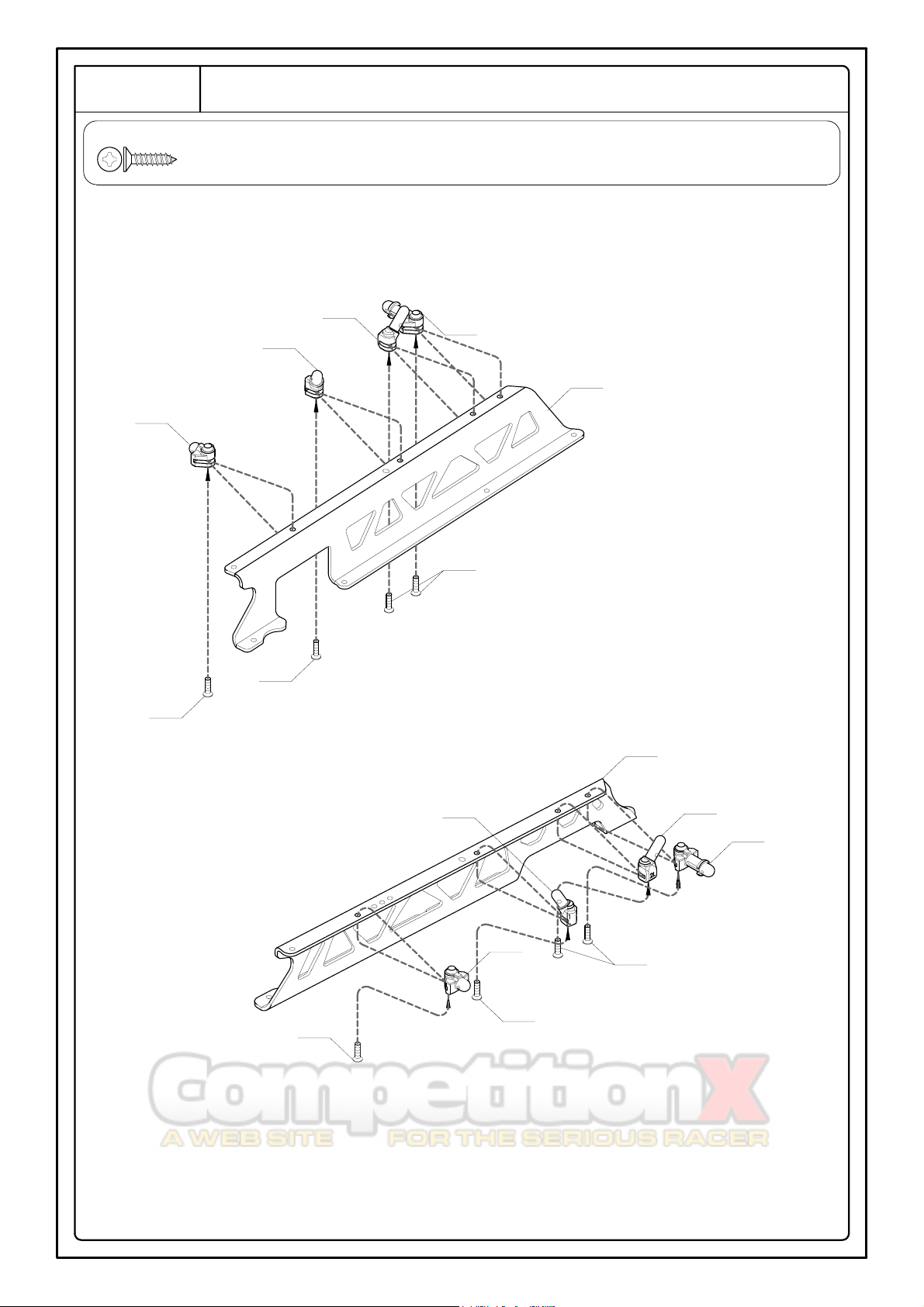
15A - F/H Tapping Screw 3x12mm -- 8
MV1674
Step 15
Side Guard
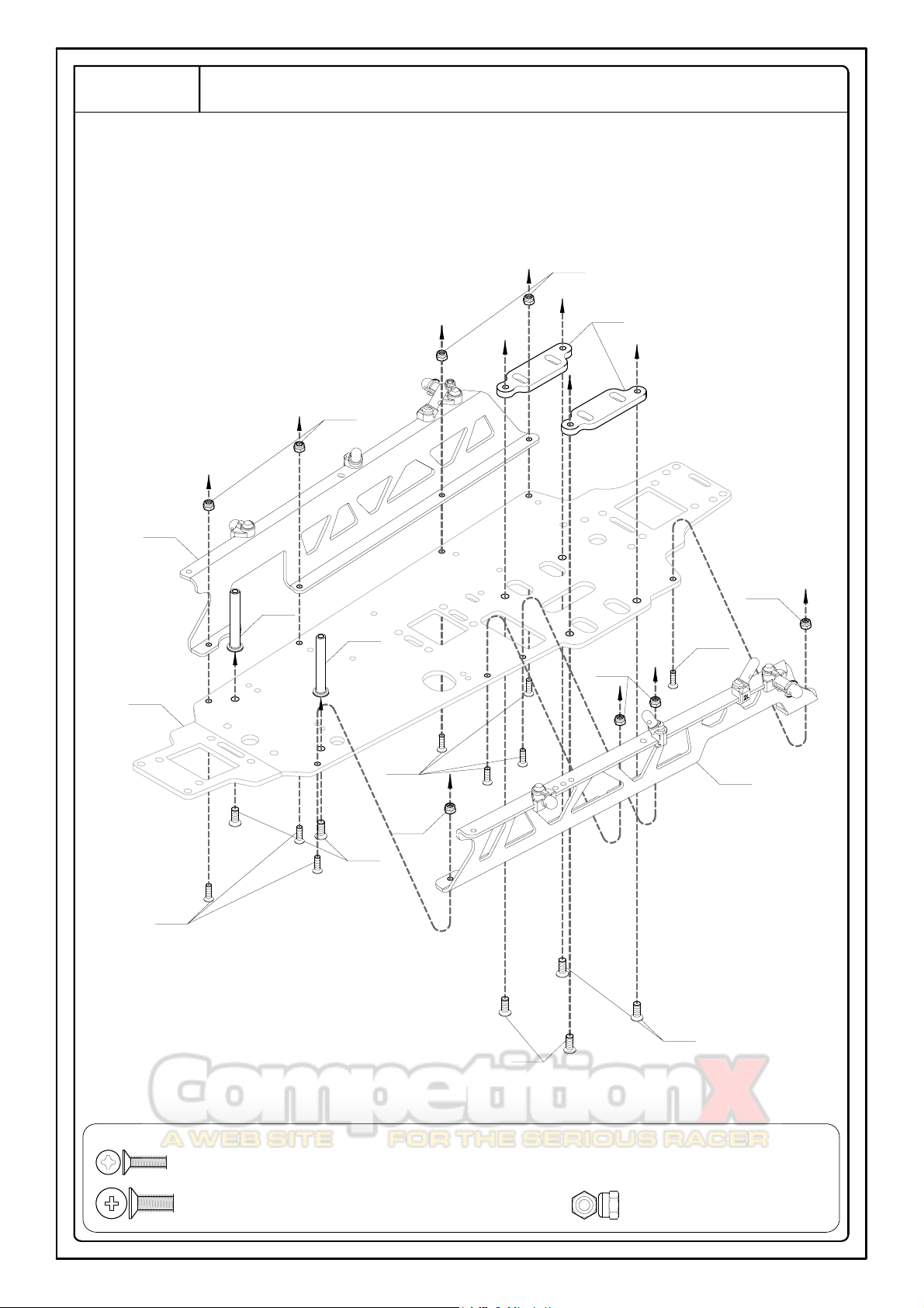
16A - F/H Machine Screw 3x10mm -- 8
16B - F/H Machine Screw 4x10mm -- 6
16C - Lock Nut 3mm -- 8
MV30101AL
Step 15
(L)
MV30731
16A
16C
16B
MV3114AL
Step 16
Chassis
Step 15
(R)
16C
16C
16C
16C
16B
16A
16A
MV30731
16B
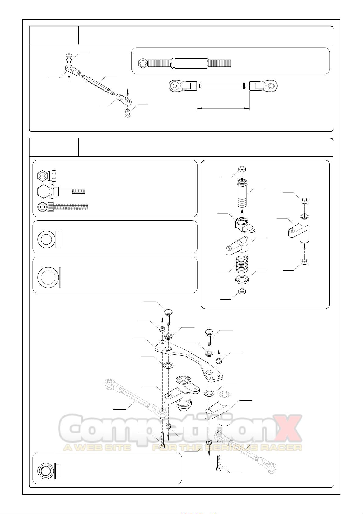
18F - Flanged Ball Bearing 5x8x2.5mm -- 2
Step 17
(R)
Step 17
(L)
18B
<18-1>
18E - Shim 8x12x0.8mm -- 2
18D - Bushing 6x10x3mm -- 4
18B - Servo Saver Screw 3x19.7mm -- 2
18C - Cap Screw 3x20mm -- 2
18A - Lock Nut 3mm -- 4
Steering
18D
30.5mm
17A - Turnbuckle 4x48mm -- 2
MV11303
V221524
17A
MV1301
V221524
MV11303
Steering Rods
18D
18D
18D
MV30731
MV30731
MV30731
MV3071
MV3071
MV3071
18B
18F
18F
18A
18A
MV30751AL
18E
18E
18A
18A
18C
18C
Step 18-1
Step 18-1
Step 17
For Right and Left Sides (x2)
Step 18
13
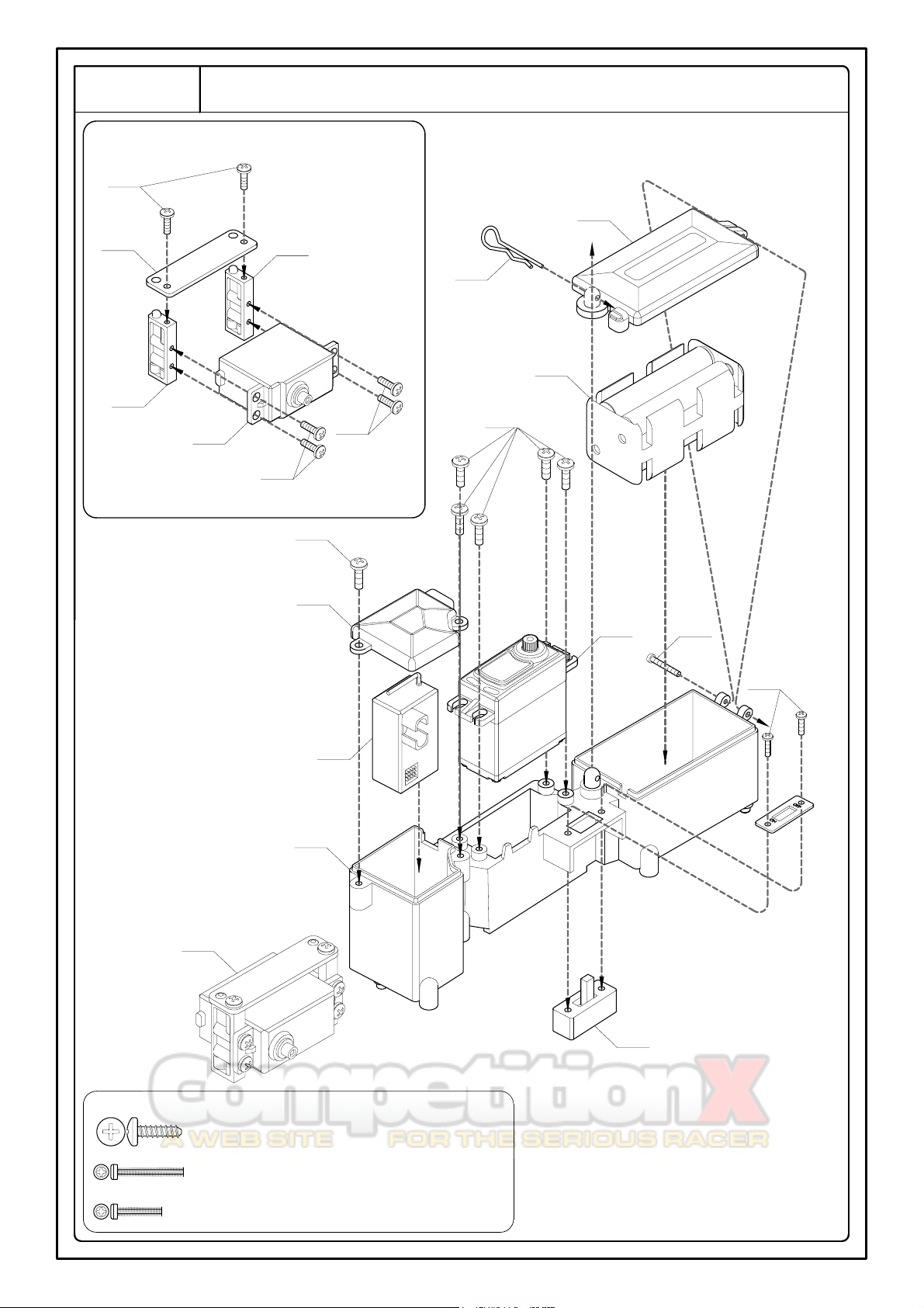
CH2
Throttle
<19-1>
19A
Battery Holder
MV3103
XV30221AL
MV37412
19A
MV3103
Receiver
Switch
Step 19-1
Step 19
19B - Round Head Machine Screw 2x15mm -- 1
19A - Button Head Tapping Screw 3x10mm -- 12
CH1
Steering
19A
19A
MV37412
MV37412
19A
19C - Round Head Machine Screw 2x10mm -- 2
19C
19B
MV120
Receiver Case
 Loading...