

Page 1
WARRANTY
Great Planes®Model Manufacturing Co.guarantees this kit to be free from defects in both material and workmanship
at the date of purchase.This warranty does not cover any component parts damaged by use or modification.In no case
shall Great Planes’ liability exceed the original cost of the purchased kit. Fur ther, Great Planes reserves the right
to change or modify this warranty without notice.
In that Great Planes has no control over the final assembly or material used for final assembly, no liability shall be
assumed nor accepted for any damage resulting from the use by the user of the final user-assembled product.By the act
of using the user-assembled product, the user accepts all resulting liability.
If the buyers are not prepared to accept the liability associated with the use of this product,they are advised
to return this kit immediately in new and unused condition to the place of purchase.
READ THROUGH THIS INSTRUCTION MANUAL
FIRST. IT CONTAINS IMPORTANT INSTRUCTIONS
AND WARNINGS CONCERNING THE ASSEMBLY
AND USE OF THIS MODEL.
GPMZ0281 for GPMQ1882 V1.1Entire Contents © Copyright 2004
Champaign, IL 61822
(217) 398-8970, Ext. 5
airsupport@greatplanes.com
INSTRUCTION MANUAL
Page 2

INTRODUCTION . . . . . . . . . . . . . . . . . . . . . . . . . . . . . . 2
PRECAUTIONS. . . . . . . . . . . . . . . . . . . . . . . . . . . . . . . 2
POINTS TO CONSIDER . . . . . . . . . . . . . . . . . . . . . . . . 3
PREPARATIONS. . . . . . . . . . . . . . . . . . . . . . . . . . . . . . 3
Adhesives and Building Supplies . . . . . . . . . . . . . . . . 3
Optional Supplies and Tools . . . . . . . . . . . . . . . . . . . . 3
Hardware and Accessories. . . . . . . . . . . . . . . . . . . . . 3
Parts Identification . . . . . . . . . . . . . . . . . . . . . . . . . . . 4
Important Building Notes . . . . . . . . . . . . . . . . . . . . . . 4
ASSEMBLY. . . . . . . . . . . . . . . . . . . . . . . . . . . . . . . . . . 5
Install the Steering Servo . . . . . . . . . . . . . . . . . . . . . . 5
Assemble the Water Rudder. . . . . . . . . . . . . . . . . . . . 6
Install the Water Rudder. . . . . . . . . . . . . . . . . . . . . . . 7
POSITIONING OF FLOATS. . . . . . . . . . . . . . . . . . . . . . 9
PREP ARE THE MODEL . . . . . . . . . . . . . . . . . . . . . . . 10
INST ALL THE FLOA TS . . . . . . . . . . . . . . . . . . . . . . . . 11
Install the Float Gear Wires. . . . . . . . . . . . . . . . . . . . 11
Install the Floats on the Model . . . . . . . . . . . . . . . . . 12
Connect the Float Servo. . . . . . . . . . . . . . . . . . . . . . 12
Install the Air Rudder Pushrod . . . . . . . . . . . . . . . . . 13
Set the Water Rudder Throw . . . . . . . . . . . . . . . . . . . 14
Install the Ventral Fin . . . . . . . . . . . . . . . . . . . . . . . . 14
Balance the Model . . . . . . . . . . . . . . . . . . . . . . . . . . 15
FLYING . . . . . . . . . . . . . . . . . . . . . . . . . . . . . . . . . . . . 15
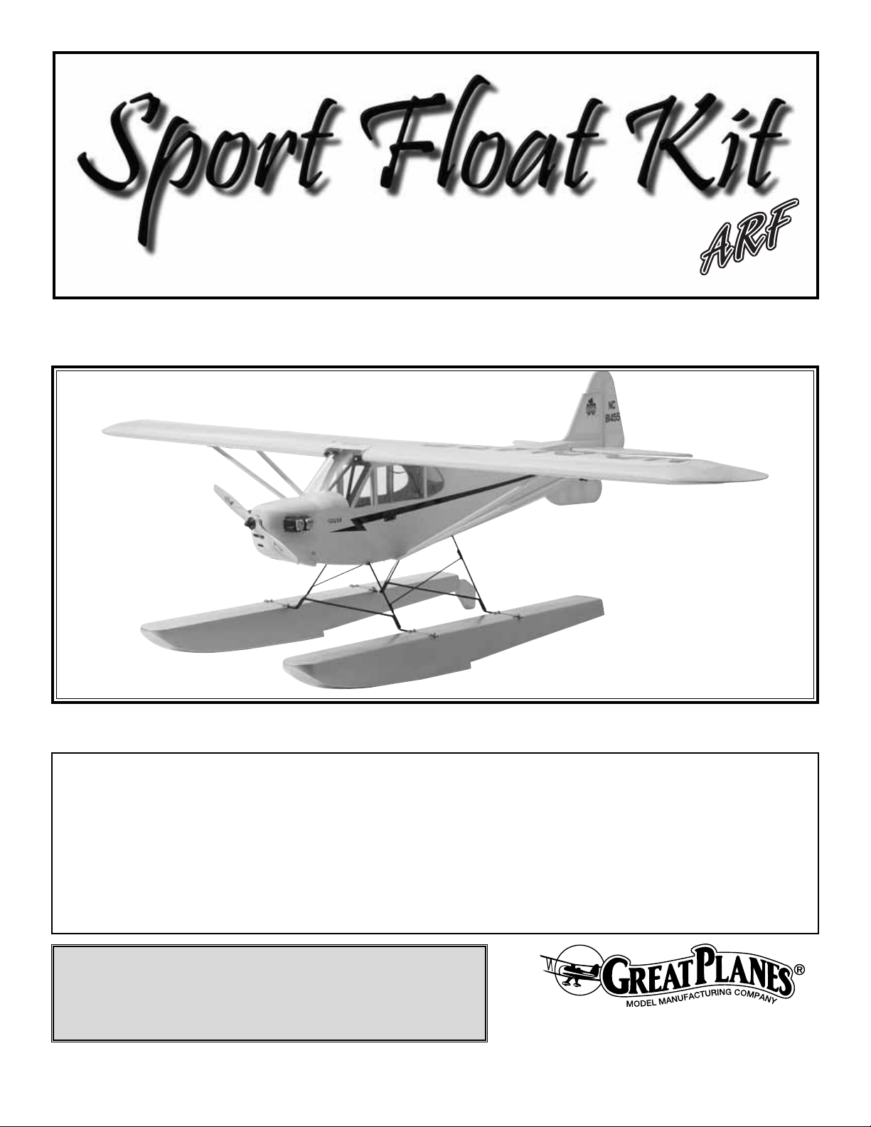
Thank you for purchasing the Great Planes ARF Sport
Floats. During our flight testing with these floats, we were
amazed by the superb handling characteristics on the water
and the ultra-smooth, realistic takeoffs and landings.
While the Great Planes ARF Sport Floats were designed for the
.40 size Great Planes Piper J-3 Cub ARF, they will work well
with other models, too.Although the Great Planes Cub ARF is
used as an example, the same procedures and guidelines apply
if you are installing your floats on a different model.
You will discover that the Great Planes ARF Sport Floats are
easily installed, often in just one hour. All of the parts you
need are included in this kit.
1. Your Great Planes ARF Sport Floats and model should
not be considered a toy, but rather a sophisticated, working
model that functions very much like a full-size airplane.
Because of its performance capabilities, the ARF Sport
Floats and model, if not assembled and operated correctly,
could possibly cause injury to yourself or spectators and
damage to property.
2. You must assemble the Sport Floats according to the
instructions. Do not alter or modify the floats, as doing so may
result in an unsafe or unflyable model. In a few cases the
instructions may differ slightly from the photos.In those instances
the written instructions should be considered as correct.
3. You must use an R/C radio system that is in first-class
condition, and a correctly sized engine and components
(fuel tank, etc.) throughout the building process.
4. You must correctly install all R/C and other components
so that the model operates correctly on the ground, on the
water and in the air.
5.You must check the operation of the model before every
flight to insure that all equipment is operating and that the
model has remained structurally sound. Be sure to check
clevises or other connectors often and replace them if they
show any signs of wear or fatigue.
6. If you are not already an experienced R/C pilot, you
should fly the model only with the help of a competent,
experienced R/C pilot.
7.You should have a boat available to retrieve your model.
Do not attempt to swim after your model.
PRO TECT YOUR MODEL,YOURSELF
& OTHERS...FOLLOW THESE
IMPORTANT SAFETY PRECAUTIONS
INTRODUCTION
TABLE OF CONTENTS
2
Page 3

Remember: Take your time and follow the instructions to
end up with a well-built model that is straight and true.
If you have not flown this type of model before, we
recommend that you get the assistance of an
experienced pilot in your R/C club for your first flights.
You’ll learn faster and avoid risking your model before you
are truly ready to fly it. Your local hobby shop has
information about clubs in your area whose membership
includes experienced pilots.
In addition to joining an R/C club, we strongly recommend you
join the AMA (Academy of Model Aeronautics). AMA
membership is required to fly at AMA sanctioned clubs. There
are over 2,500 AMA chartered clubs across the country .Among
other benefits, the AMA provides insurance to its members who
fly at sanctioned sites and events. Additionally, training
programs and instructors are availab le at AMA club sites to help
you get started the right way .Contact the AMA at the address or
toll-free phone number below:
Academy of Model Aeronautics
5151 East Memorial Drive
Muncie, IN 47302-9252
Tele. (800) 435-9262
Fax (765) 741-0057
Or via the Internet at: http://www.modelaircraft.org
For steering your model on the water, a water rudder will be
installed on the right float.The water rudder can be connected
to the aircraft rudder by a pushrod, or a servo can be installed
inside the float. All parts required for either type installation are
included with this kit (servo not included).
We highly recommend that you install a servo inside the
float. It is easy to do and it makes installation/removal of the
floats on the aircraft easier.
Floats increase the weight of the model they are installed
on. In addition, water drag and surface tension increase the
amount of power required for takeoff. In-flight drag is also
greatly increased.
If your model had “adequate” power before floats are installed,
it will likely be very marginally powered with the floats. It is
recommended that you use an engine in the upper end of the
recommended power range with these floats.
For the .40 size Great Planes Piper J-3 Cub ARF, we recommend
an O.S.®.46 FX 2-stroke or an O.S.FS 70 4-stroke engine.
❏ 1/2 oz. [15g] Thin Pro™CA (GPMR6001)
❏ 1/2 oz. [15g] Medium Pro CA+ (GPMR6007)
❏ Pro 6-minute epoxy (GPMR6045)
❏ 2-56 Tap and Drill (GPMR8100)
❏ Stick-on segmented lead weight (GPMQ4485)
❏ #1 Hobby knife (HCAR0105)
❏ #11 blades (5-pack, HCAR0211)
❏ Clear water proof tape
❏ Dr ill bits: 1/16” [1.6mm], 5/64" [2mm], 1/8" [3.2mm].
(25/64" or 3/8" [9.9 or 9.5mm] for optional
servo installation.)
❏ Razor saw
❏ 2 oz. [57g] spray CA activator (GPMR6035)
❏ CA applicator tips (HCAR3780)
❏ CA debonder (GPMR6039)
❏ Mixing sticks (50, GPMR8055)
❏ Mixing cups (GPMR8056)
❏ Pliers with wire cutter (HCAR0630)
❏ Denatured alcohol (for epoxy clean up)
❏ Z-bend pliers (HCAR2000)
❏ Rotar y tool such as Dremel
®
❏ Rotar y tool reinforced cut-off wheel
❏ Ser vo horn dr ill (HCAR0698)
❏ CG Machine™(GPMR2400)
For internal servo:
❏ (1) standard ser vo
❏ (1) 12" [300mm] ser vo extension
❏ (1) Y -harness
Hardware & Accessories
Optional Supplies & Tools
Adhesives & Building Supplies
PREPARATIONS
POINTS TO CONSIDER
3
Page 4
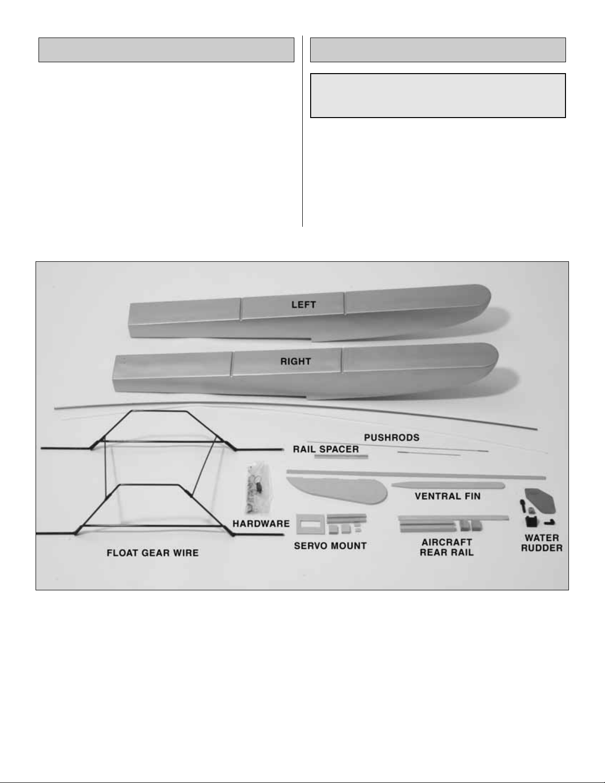
Before starting to build, use the Parts Identification list to
take an inventory of this kit to make sure it is complete, and
inspect the parts to make sure they are of acceptable
quality. If any parts are missing or are not of acceptable
quality, or if you need assistance with assembly, contact
Product Support. When reporting defective or missing
parts, use the part names exactly as they are written in the
Kit Contents list on this page.
Great Planes Product Support:
Telephone: (217) 398-8970
Fax: (217) 398-7721
E-mail: airsupport@greatplanes.com
If you are not going to install a servo inside the float, skip the
following section and go to “Assemb le the Water Rudder”on
page 6.
Before starting assembly, assemble the model and mark
the balance point of the model.You will need to know this
later when the model is balanced with the floats installed.
Important Building NotesParts Identification
4
Hardware bag contents:
(3) SMALL NYLON TIE STRAP
(3) FLAT LANDING GEAR STRAPS, TREE OF 4
(34) #4 X 1/2" PHILLIPS HEAD SHEET METAL SCREW
(4) WHEEL COLLAR SET SCREW
(4) 5 mm WHEEL COLLAR
(35) #4 FLAT WASHER
(1) 2-56 HEX NUT
(1) 4-40 LOCK NUT
(4) #62 RUBBER BAND
(1) 2-56 X 3/8" PHILLIPS HEAD SHEET METAL SCREW
(1) 4-40 X 1/4" SOCKET HEAD CAP SCREW
(3) 2-56 X 1/2" PHILLIPS HEAD MACHINE SCREW
(1) BRASS BODY FOR SCREW-LOCK CONNECTOR
(1) NYLON RETAINER
(1) FASLINK
(1) RUBBER BOOT
(1) 4-40 x 1/8" SOCKET HEAD CAP SCREW
(1) LARGE NYLON CONTROL HORN
(1) 5/32" GEAR HUMP STRAP, TREE OF 4
(2) NYLON CLEVIS
(2) SILICONE CLEVIS RETAINER
(1) 2-56 X 1" ROD THREADED FULL LENGTH
(1) 2-56 x 6" THREADED ONE END WIRE
Page 5
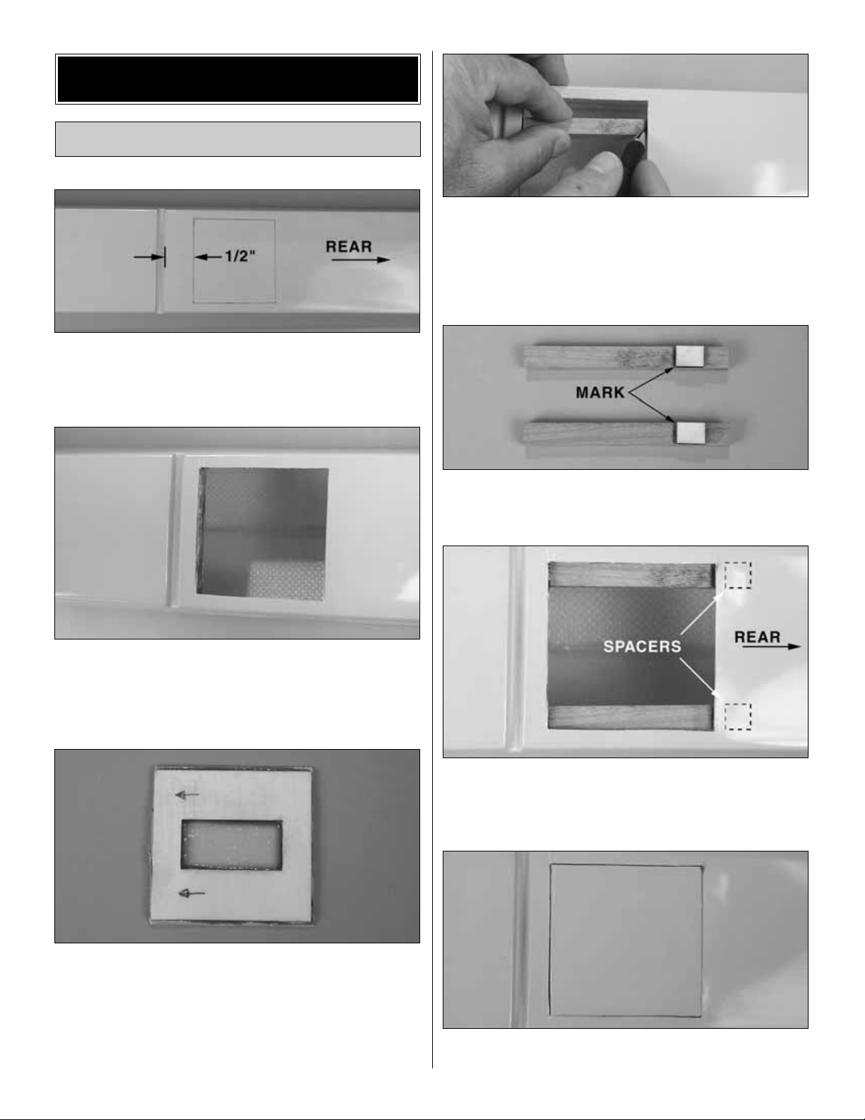
❏ 1. Use the servo tray to mark the outline of the tray on
one of the floats with a fine-tipped marking pen as shown in
the photo above.The tray should be located 1/2" [13mm] aft
of the rear groove in the float.This float is now the right float.
❏ 2. Very carefully cut the marked area from the float with
a razor saw. The piece you cut out will be used as the tray
cover, so use care not to damage it. Mark the end of the
cover that was facing forward.
❏ 3. Glue the servo tray to the inside of the cover with
epoxy. Use some medium grit sandpaper to rough up the
inside of the cover first. Mark the tray indicating which end
of the cover faces forward.
Note: The tray may not have the cutout shown in the
above photo.
❏ 4. Clean any resin residue from the tray opening in the
float.Trim any resin from the hardwood mounting rail inside
the float. Put one of the 1/4" x 3/8" x 3-1/2" [6.4 x 9.5 x
89mm] basswood servo tray rails in the float, butting one
end against the mounting rail. Mark the rear of the opening
on the rail.Transfer the mark to the other rail as well.
❏ 5. Glue a 1/8" x 3/8" x 1/2" [3.2 x 9.5 x 12.7mm] ply rail
spacer to each of the servo tray r ails as shown in the photo.
In the photo, the mark is to the left of the spacers.
❏ 6. Using medium CA, tack glue the servo tray rails into
the float opening with the spacers toward the rear of the
float. Scuff the area with some medium grit sandpaper to
improve the adhesion.
❏ 7. Trial fit the servo tray to the top of the rails. If the tray
sticks up above the top of the float, remove the servo tray
Install the Steering Servo
ASSEMBLY
5
Page 6

rails and make some shims from leftover ply.Tack glue the
servo tray rails in place again and check the fit of the servo
tray. When satisfied with the fit, use 6-minute epoxy to glue
the rails permanently in place.
❏ 8. Mount the ser vo to the 5/16" x 3/4" x 7/8" [8 x 19 x
22.2mm] basswood blocks, using the hardware supplied
with the servo.Make sure the servo is oriented as shown in
the photo with the servo arm pointing as shown. The edge
of the block should extend past the rear side of the servo
slightly. See the photo at step 10.
❏9.Position the servo tray as shown and mark the location
of the mounting rails.
❏ 10. Use 6-minute epoxy to glue the basswood blocks to
the servo tray, with the servo attached.The servo should be
centered between the lines marking the location of the rails.
After the epoxy has cured, install the tray into the opening
in the float and make sure it fits properly.
❏ 1. If your water rudder is already assembled, proceed to
step 7. Otherwise, refer to the above photos as you
assemble the water rudder.
❏ 2. Drill two 1/8" [3.2mm] holes in the aluminum water
rudder at the locations shown in the above photo.
❏ 3. Drill and tap a 2-56 hole in the nylon rudder post at
the location shown in the above photo .Install the 2-56 x 1/2"
[12.7mm] screw in the hole.
Assemble the Water Rudder
6
Page 7

❏ 4. Assemble the Nylon rudder bearing, rudder post,
aluminum bracket and nylon control horn as shown in
the photo. Hold the control horn in place with a #2 x 3/16"
[4.8mm] screw.
❏5. Assemble the water rudder to the aluminum brac k et with a
4-40 x 1/4" [6.4mm] socket head cap screw and 4-40 lock
nut. Tighten the nut, but leave it loose enough that the water
rudder can pivot freely in the bracket. If the bracket does not
have a hole drilled in it, use a 1/8" drill to drill the hole.
❏ 6. Drill a 5/64" [2mm] hole in the aluminum bracket and
rudder post at the location shown in the above photo,
making sure the water rudder and control horn are aligned
as shown. Install a 2-56 x 3/8" [9.5mm] screw and 2-56 nut
to hold the bracket to the rudder post.Use Great Planes Pro
Threadlocker™to hold the nut in place.
Hint: Center punch the bracket before drilling the hole.
❏ 7. Install a screw-lock connector, nylon retainer and
4-40 x 1/8 [3.2mm] socket head cap screw in the outer
hole of the long tiller arm on the water rudder. Also install
the rubber band.
If you are installing a servo inside the right float, proceed to
step 2.
❏ 1. Do this step only if you are installing a pushrod from the
aircraft rudder to the water rudder. Mount the water rudder
assembly in the location shown in the above photo.The top of
the mounting bracket should be even with the top of the float,
on the centerline of the transom (rear of the float). Mark the
location of the holes in the mounting bracket on the transom.
Drill a 5/64" [2mm] hole at the marked locations and mount the
water rudder assembly to the transom with two #4 x 1/2"
[12.7mm] sheet metal screws and two #4 flat washers.
Proceed to “Prepare the Model” on Page 10.
Install the Water Rudder
7
Page 8

❏2. Mount the water rudder assembly in the location shown in
the above photo. The top of the mounting bracket should be
3/4" [19mm] from the top of the float, on the centerline of the
transom (rear of the float).Mark the location of the holes in the
mounting bracket on the transom. Drill a 5/64" [2mm] hole at
the marked locations and mount the water rudder assembly to
the transom with two #4 x 1/2" [12.7mm] sheet metal screws
and two #4 flat washers.
❏ 3. Drill a 25/64" [9.9mm] hole in the transom of the float
as shown. This hole must be drilled very carefully as there
is a wood block installed in the transom for mounting the
water rudder assembly. If the hole is drilled too close to the
water rudder assembly, the drill bit will catch on the edge of
the wood block, causing the drill bit to twist sideways. Hold
the float up to a strong light so that you can determine
where the edge of this block is located. Drill the hole as
close to the water rudder assembly as possible, while still
missing the wood block. If you can't locate the edge of the
wood block, drill a locating hole as noted in the photo. If the
locating hole hits wood, drill another hole farther over.
Note:If you don’t have a 25/64" [9.9mm] drill use a 3/8" [9.5mm]
drill, and then slightly enlarge the hole with a hobby knife.
❏ 4. Cut the .074 x 17-1/2 [445mm] wire pushrod to a
length of 12" [25.4mm]. Cut the threaded portion of the wire
off, leaving a 12" [25.4mm] wire with no threads. Make a
small bend 3/4" [19mm] from the end of the wire. Insert the
wire into the rubber bushing.
❏ 5. Insert the wire and r ubber bushing into the hole you
drilled in the transom.The rubber bushing is easier to insert
if you stretch it on the wire as it is inserted. Use a
screwdriver to carefully poke it through as needed. The
rubber bushing is now inside the float. Secure the rubber
bushing to the transom with some silicone rubber glue or
medium CA. Insert the wire into the screw-lock connector.
❏ 6. Mark the location of the hole in the ser vo arm on the
servo mounting rail and on the wire pushrod.Make sure that
the water rudder is centered and the pushrod is centered in
the screw-lock connector.
❏ 7. Make a 90-degree bend in the wire at the mark. The
bend should face the right side of the float as shown in the
photo.Enlarge the middle hole of the servo arm with a 5/64"
[2mm] drill. Insert the pushrod into the servo arm and
secure it with a Faslink connector. Remove the screw and
servo arm from the servo. Plug the ser vo into the receiver
and center the trims on the transmitter. Turn the radio on,
and then push the servo arm onto the servo with the arm at
90 degrees to the servo.Install the mounting screw into the
servo arm. Turn the radio off and unplug the servo.
8
Page 9

❏ 8. Cut a small notch in the servo hatch for the servo
extension wire. Install a 12" servo extension wire on the
servo lead. Secure the connection with tape, keeping the
connection as water tight as possible. Position the servo
hatch onto the rails with the taped connection inside the
float. Secure the hatch into place with some clear
waterproof tape. Put a dab of silicone glue where the servo
wire exits the hatch to waterproof it.
Before you continue, take a break from building and
study the following information to be sure you
understand the positioning of the floats in relation to
the wing and fuselage.
While the following instructions show the Sport Floats on
Great Planes Piper Cubs, there are general tips and
guidelines that apply to all models which will insure proper
handling characteristics in the water and good landing and
takeoff tendencies.
The relationship between the “step” on the floats and the
center of gravity on the model is important. First, the floats
should be mounted on the model so the step is positioned as
detailed in the “Step Sketch” for your particular model. Then,
when the floats are mounted on the model, move the C.G.
slightly forward as listed below. Although you may ha v e added
the recommended ballast inside the front of the float, in some
cases a little more ballast may be required on the model.
• For 60-size floats: Move the CG (Balance point) 1/2"
ahead of the manufacturers recommended CG.
• For 40-size floats: Move the CG (Balance point) 3/8"
ahead of the manufacturers recommended CG.
• For 20-size floats: Move the CG (Balance point) 9/32"
ahead of the manufacturers recommended CG.
Another important relationship between the wing and the
floats is the relative “angle of attack.’’ With a virtually flat
bottom wing such as a Piper Cub, the deck of the floats
should be parallel to the bottom of the wing. Since the Cub
does not have a truly flat wing, this yields a slight positive
wing incidence in relation to the floats, and the airplane will
tend to rise off the water at the correct time. If you have a
model with a symmetrical wing, the wing incidence in
relation to the float deck should be positive 1-1/2 degrees.
Finally, each float should be set so that it is parallel to the
centerline of the fuselage.
POSITIONING OF FLOATS
9
Page 10

❏ 1. Install a 5mm wheel collar and set screw on each of
the four ends of the float gear wires.The photo shows the
two right ends of the gear wires.
You must now determine how the floats will be mounted to
your model. In most cases, you will be able to use the
existing landing gear mounting block, already installed in
your model, for the front mount of the float wires. You will
probably need to install a rear mount, however.
If you are installing the floats on a recently produced Great
Planes J-3 ARF (fabric covered), the model may already
have the rear mount installed.Other models will require that
you install a rear mounting block.
❏ 2. Place the fuselage of your model on your work bench,
upside down. Place the float gear wires on the fuselage.
Determine if there is a rear mounting block in your model.If
there is, cut the covering from the groove in the block, then
proceed to “Install the Float Gear Wires” on page 11.
❏ 3. If there is no rear mounting block, you must install one.
Remove the landing gear from your model.Place the float gear
wires on the model and mark the location of the rear float wire.
Note that we have reinstalled as man y of the screws, etc.as we
could, so as not to lose them and to seal the holes in the
bottom of the fuselage. In the steps that follow, we will show
how we installed the mounting block in the Great Planes J-3
ARF.Your model may require some changes.
❏ 4. Check for a former inside the fuselage in the location
you have marked. Use a pin to poke through the bottom of
the fuselage and locate the edge of the former.Notice in the
photo how the mounting block will fit against the former.Do
not be concerned if your model does not have a former that
is so conveniently located.
❏ 5. Mark the outline of the mounting block on the fuselage
bottom so that the groove in the mounting block will be
directly under the location of the wire already marked on the
fuselage. Cut the covering and balsa sheeting from the
fuselage at the marks. Save the covering.
PREP ARE THE MODEL
10
Page 11

❏6.This fuselage has a 1/8" [3.2mm] balsa side and a 1/8"
[3.2mm] ply doubler. There is also a 1/4" x 1/4" [6.4 x
6.4mm] balsa filler stick glued to the bottom sheeting and
resting on the edge of the ply doubler. Cut the stick and
fuselage side down to the ply doubler. Do not cut deeper
than 1/2" [12.7mm], the thickness of the mounting block.
❏ 7. After cutting down to the ply doubler, the mounting
block will likely protrude from the bottom of the fuselage
slightly; in our case it was 1/8". Trim the fuse side and ply
doubler until the mounting block is flush with the bottom of
the fuselage.
❏ 8. Using epoxy, glue the 1/2" x 3/4" x 1" [12.7 x 19 x
25.4mm] support blocks to the fuselage sides as shown in
the photo. If your model does not have a former that the
mounting block can be glued to, you should make longer
support blocks to provide additional support.
❏ 9. Using epoxy, glue the mounting block to the support
blocks, fuselage sides and former. Glue a filler strip to the
mounting block, if needed, so that the bottom sheeting can
be glued to the mounting block.
❏ 10. Use the covering that you saved to cover the mounting
block and the fuselage sides. There may not be enough
covering, so do the visible part of the fuselage sides first.
Leftover Cub Yellow MonoKote®can be used on the bottom.
If the landing gear is still installed on the model, remove it.
Set the parts aside where you won’t misplace them.
❏ 1. Install four nylon landing gear straps on each float
using eight #4 x 1/2" [12.7mm] sheet metal screws and
eight #4 flat washers. The side of the straps should be
Install the Float Gear Wires
INST ALL THE FLOA TS
11
Page 12

about 3/8" [9.5mm] from the sides of the floats. Drill 1/16"
[1.6mm] pilot holes for the screws.
❏ 2. Mount the floats to the float gear wires, making sure
the right float is on the right side. Note the orientation of the
wires on the floats.
❏ 1. Install two nylon landing gear straps on the rear
fuselage mounting block using four #4 x 1/2" [12.7mm]
sheet metal screws and four #4 flat washers. Drill 1/16"
[1.6mm] pilot holes for the screws.
❏2.Place the floats and wires into position on the fuselage.
Secure the rear wire in place with the landing gear straps.
❏3.Waterproof the ply spacer assembly with some thin CA or
paint.Install the ply spacer assembly in the front gear wire.This
will prevent the forward float wire from moving in the groove.
Secure the wire into place with the landing gear straps.
❏4. Remove all of the mounting scre ws from the fuselage and
floats.Harden all of the holes with a couple of drops of thin CA.
After the CA cures, reinstall all of the screws.
If you have not installed an internal servo , proceed to “Install
the Air Rudder Pushrod” on page 13.
❏ 1. Plug a “Y” connector into the rudder channel on the
receiver. Plug the rudder ser vo into one end of the “Y.” Route
the other end of the “Y” to the right rear float wire area.
Note: If you have a computer radio system, you could use a
spare receiver channel for the water rudder servo and mix
the air rudder to the water rudder servo. This would allow
independent setup of the throws and trim.
❏ 2. Cut a small slot in the fuselage side for the connector.
Connect the Float Servo
Install the Floats on the Model
12
Page 13

❏ 3. Use the small nylon tie straps to secure the servo
extension wire to the float landing gear wires.Plug the servo
extension wire into the “Y”connector from the receiver.
IMPORTANT: Secure the connection with tape, keeping the
connection as water tight as possible.Inser t the connection
into the fuselage so that it is entirely inside the fuselage.
Seal the cutout and wire with some clear silicone sealant.
Continue with “Set the Water Rudder Throw.”
❏1. Install a large nylon control horn on the right side of the
rudder as shown in the photo above. Use two 2-56 x 1/2"
[12.7mm] screws and the nylon back plate to mount the horn.
❏ 2. Install a nylon clevis, clevis retainer and 2-56 x 1"
[25.4mm] threaded stud on the inner pushrod. Thread
the stud about 13 turns into both the clevis and pushrod.
Insert the inner pushrod into the outer pushrod tubing.
❏ 3. Attach the pushrod assembly to the rear of the
fuselage with a nylon strap and two #4 x 1/2" [12.7] screws
and two #4 flat washers. Drill 1/16" [1.6mm] pilot holes for
the screws. Connect the clevis to the control horn in the
second hole closest to the rudder.
❏4. Route the assembled pushrod to the water rudder.Attach
the pushrod to the float landing gear wires with the small nylon
tie straps.The above photo shows the finished installation.
USE THIS PHOTO FOR THE NEXT FOUR STEPS
❏ 5. Use the photo above as a guide in cutting the pushrod
to length. With the pushrod properly positioned, mark the
Install the Air Rudder Pushrod
13
Page 14

pushrod 1/8" [3.2mm] from the rear of the float. Cut the
inner and outer pushrods at the marked location.
❏ 6. Disconnect the pushrod clevis from the rudder control
horn and pull the inner pushrod out a few inches. Cut the
outer pushrod 3/8" [9.5mm] from the end (at the float end).
Reconnect the clevis back to the control horn.
❏ 7. Thread the 2-56 x 6" [152mm] wire 13 turns into the
inner pushrod. Insert the wire into the screw-lock connector
on the water rudder control arm and cut the wire to length.
❏ 8. Attach the pushrod assembly to the rear of the float
with a nylon strap and two #4 x 1/2" [12.7] screws and two
#4 flat washers.
❏ 9. Center the rudder and tighten the screw on the
screw-lock connector.
Note:Two additional nylon straps and screws are included if
additional support is needed.
❏ 1. Turn on the transmitter and receiver. With the r udder
centered, adjust the water rudder linkage as needed to
center the water rudder.
❏2.Move the rudder left and right with the transmitter stick.
Make sure the water rudder responds smoothly and in the
correct direction.
❏ 3. Adjust the linkage for a water rudder throw of 1"
[25.4mm].This can be done by moving the clevis to another
hole on the rudder control horn (external pushrod) or by
adjusting the ATV (internal servo). The amount of throw
should be adjusted as needed for good water handling.
Floats on a model generally add more side area forward of
the CG than aft.This can create a stability problem. This kit
includes a ventral fin that can be installed on the rear of the
fuselage to increase the rearward side area. The Great
Planes J-3 ARF flies well without the ventral fin. However,
there is noticeably less yaw stability.
❏ 1. Remove the covering from the slots in the ventral fin
mounting base.
❏ 2. Inser t the ventral fin in the mounting base. Mark the
fin where it meets the mounting base.Remove the covering
from the fin and mounting base at the marks.
❏ 3. Mount the ventral fin base to the bottom rear of the
fuselage with four #4 x 1/2" [12.7mm] screws and four #4
flat washers. Drill 1/16" [1.6mm] pilot holes for the screws.
Enlarge the holes in the mounting base only with a 1/8"
[3.2mm] drill bit.Harden the holes in the fuselage with some
thin CA.
❏ 4. Tack glue the ventral fin to the mounting base with
medium CA. Be very careful not to glue the mounting base
to the fuselage.
Install the Ventral Fin
Set the Water Rudder Throw
14
Page 15

Note: Make sure the ventral fin is perpendicular to the
bottom of the fuselage.
❏ 5. Remove the ventral fin assembly from the fuselage.
Solidly glue the ventral fin to the mounting base.
Most models are less stable with floats installed.The airflow
across the model is considerably different and the weight of
the floats is well below the CG, causing a pendulum effect
when the model is turned or rolled. In addition, the total
weight of the model is considerably higher. For these
reasons the model will not fly as you have become
accustomed to in the past.
For the first few flights with the floats installed, we
recommend that you balance the model for a somewhat
more nose heavy condition.This will increase the stability of
the model until you become accustomed to the changed
handling characteristics of the model. Remember that the
model is heavier and you must increase the takeoff and
landing speeds accordingly.
❏1.Place a mark 1/4" forward of the mark you made bef ore
you installed the floats. This will give a balance point 1/4"
more nose heavy.
❏ 2. With the model assembled and the fuel tank empty,
balance the model at the new balance point. It is likely that
you will need about two ounces of lead to accomplish this.
Note:The added lead required to balance the model can be
added to the firewall or to the front of the floats. We
recommend that you add it to the top front of the floats,
though this is a bit unsightly.In the future when you remove
the floats and install the normal landing gear (and vice
versa), you won’t need to be concerned with removing or
adding weight – or forget to do so.
Before setting the model in the water, be sure the water
rudder on the float is extended. A reliable, slow idle is a
must. First flight attempts with floats should be reserved for
relatively calm days when the water is not very choppy.
Practice taxiing around in the water to learn the handling
characteristics, and see if you hav e built in enough throw on
the water rudder. Make adjustments if required. During
taxiing, hold “up” elevator to keep the nose of the aircraft
high and the propeller out of the water spray.
Always takeoff into the wind. Gently add throttle and
gradually release some of the up elevator as the speed
increases and the aircraft lifts “on the step”of the floats.Just
like the model takes off on the ground, when it has enough
speed it will lift into the air – don’t force it off. If the surface
of the water is very smooth, it may take a bit more elevator
to break the aircraft free of the surface tension of the water.
Continue a gradual, conservative climb out until you are at
an altitude where you are comfortable making the downwind
turn. Remember, the aircraft is heavier and has more drag
than you are used to.Many modelers snap roll into the water
on takeoff because they do not gain enough speed to allow
for the added weight and drag.
Learn the flight characteristics of the model with the added
weight and drag of the floats.The aerobatic response of the
model will be considerably different with the floats installed.
While the model should be perfectly capable of loops, rolls,
stall turns and inverted flight – these maneuvers will require
a much different pilot technique to do well.
Landing approach is the same on water as it is on land.Touch
down slowly to avoid bouncing the aircraft off the water and
back into the air. There is nothing that compares to a slow,
smooth touchdown on the water. “Crabbing” or “Slipping” is a
great technique used to bleed off excess airspeed during an
approach. This is done by applying a balance of rudder and
opposite aileron to make the aircraft fly “sideways”.The path of
the aircraft is “down the runway” while the nose is pointing off
to one side.Just before the floats contact the water , release the
rudder and opposite aileron.
Although it is difficult to do, the model can contact the water at
such an angle as to allow the tips of the floats to “catch”the tops
of any wav es , thus flipping the model immediately. A v oid letting
the floats contact the water at anything but a level attitude;and
slightly nose high if there is much wave action.
Be considerate of others at the lake and enjoy your Great
Planes ARF Sport Floats.
FLYING
More than any other factor, the C.G. (balance point) can
have the greatest effect on how a model flies, and may
determine whether or not your first flight will be
successful. If you value this model and wish to enjoy it for
many flights, DO NOT OVERLOOK THIS IMPORTANT
PROCEDURE. A model that is not properly balanced will
be unstable and possibly unflyable.
Balance the Model
15
Page 16

GPMR6002 Thin Pro CA 1 oz.
GPMR6008 Medium Pro CA+ 1 oz.
GPMR6045 Pro 6-Minute Epoxy 9 oz.
High-quality Pro Adhesives provide
model building’s best bonds...and a
“Best If Used By” date on the label for
visible proof of freshness! Thinformula Pro CA offers instant bonds,
curing in just 1-3 seconds – it’s ideal for most assembly
needs. Medium CA+ is an excellent gap filler that cures in
10-15 seconds for a little more positioning time. The
uniquely precise cure time of Pro 6-Minute Epoxy allows
you to continue building with the confidence that epoxied
parts won’t be accidentally bumped out of alignment.
These pliers automatically locate the precise Z-bend point
for maximum servo arm performance – and they’re so easy
to use, even inexperienced modelers can make perfect
Z-bends in minutes.Just insert the pliers’ alignment pin into
the servo horn hole that your pushrod will be connected to,
and lightly hold the music wire where the bend will be
placed.Remove the pliers from the servo horn, squeeze the
handles, and make the bend...exactly where you need it!
Works with wire up to 1/16" in diameter.
This standard servo with preinstalled, round servo horn is
ideal for car, boat and other applications. It comes with “J”
connector on a 5 in.lead and hardware, including four brass
eyelets, four rubber grommets, four mounting screws, and
large and small “X” horns. Speed: 0.23 sec/60 degrees
(4.8V). Torque: 44.4 oz-in (4.8V). Weight: 1.31 oz [37.2g].
Dimensions: 1.59 x 0.78 x 1.42 in [40.4 x 19.8 x 36mm].
Every
flier needs this ingenious tool! For optimum
performance – or to achieve specific flight characteristics –
every plane must be balanced correctly. Yet checking the
balance in the “traditional” way (by hand) has always been
difficult and imprecise.The C.G. Machine makes balancing
easy and exact:Its slanted wire balancing posts accept any
plane up to 40 lb...built-in rulers position it exactly at the
recommended center of gravity. There’s no guesswork!
Great Planes®Precision Z-Bend Pliers
(GPMR8025)
Great Planes®Pro™Adhesives
Futaba®S3003 Standard Servo
(FUTM0031)
Great Planes®C.G. Machine™Airplane Balancer
(GPMR2400)
 Loading...