

Page 1

WARRANTY
Great Planes Model Manufacturing Co. guarantees this kit to be free from defects in both material and
workmanship at the date of purchase. This warranty does not cover any component parts damaged by use or
modification. In no case shall Great Planes' liability exceed the original cost of the purchased kit. Further, Great
Planes reserves the right to change or modify this warranty without notice.
In that Great Planes has no control over the final assembly or material used for final assembly, no liability shall be
assumed nor accepted for any damage resulting from the use by the user of the final user-assembled product. By the
act of using the user-assembled product, the user accepts all resulting liability.
If the buyers are not prepared to accept the liability associated with the use of this product,they are advised
to return this kit immediately in new and unused condition to the place of purchase.
READ THROUGH THIS INSTRUCTION MANUAL
FIRST. IT CONTAINS IMPORTANT INSTRUCTIONS
AND WARNINGS CONCERNING THE ASSEMBLY
AND USE OF THIS MODEL.
FLT246P1 V2.0 Printed in USA Entire Contents © Copyright 2004
P.O.Box 788 Urbana, IL 61803 (217) 398-8970
INSTRUCTION MANUAL
SPORT FLOAT KITSPORT FLOAT KIT
SPORT FLOAT KIT
For R/C Aircraft
Page 2

INTRODUCTION...............................................................2
PRECAUTIONS.................................................................2
PREPARATIONS...............................................................2
Covering method ............................................................2
Suggested tools and supplies.........................................3
Other suggested items....................................................3
Get ready to build ...........................................................3
Parts identification ..........................................................3
Die-cut patterns........................................................4 & 5
60 FLOATS PREASSEMBLY............................................6
Spine...............................................................................6
Forward keel...................................................................6
Sides and deck...............................................................6
CONSTRUCTION OF 20, 40, 60 SPORT FLOATS...........6
Framing...........................................................................6
Aft stringers ....................................................................8
Forward stringers............................................................8
Prepare for sheeting.......................................................9
Aft bottom sheeting.........................................................9
Forward bottom sheeting................................................9
Nose block and finishing...............................................10
COVERING......................................................................11
Covering method ..........................................................11
MonoKote film...............................................................11
Glass cloth & resin........................................................11
POSITIONING OF FLOATS ............................................12
Prepare your airplane to accept the floats....................13
60 FLOATS ONLY ...........................................................14
Notes about soldering...................................................14
Solder the cross braces................................................14
Mount the struts to the floats
and solder the diagonal braces.....................................15
Mounting the 60 floats ..................................................16
20 AND 40 FLOATS ONLY..............................................16
Mount the struts to the floats ........................................16
Mount the floats to the airplane ....................................16
ALL MODELS .................................................................17
Build the rudder ............................................................17
Pushrod hookup............................................................17
Connect the rudder ......................................................18
(20 and 40 floats)......................................................18
(60 floats)..................................................................19
VENTRAL FIN.................................................................19
BEFORE GOING TO THE LAKE.....................................20
WATERPROOFING.........................................................20
FLYING............................................................................20
Thank you for purchasing the Great Planes Sport Floats.
During our first flight tests with our Piper Cub 60 and Cub
20 on floats, we were amazed by the superb handling
characteristics on the water and ultra–smooth, realistic
takeoffs.Of course, the Great Planes Sport Floats will work
well with other models too.
The 20, 40 or 60 Sport Floats may be properly assembled
from this single manual. Although the Great Planes Piper
Cubs are used as examples, the same procedures and
guidelines apply if you are installing your floats on a
different model.
Please inspect all parts carefully before starting to
build! If any parts are missing, broken or defective, or if
you have any questions about building or flying these
floats, please call us at (217) 398-8970. If you are
calling for replacement parts, please look up the part
numbers and the kit identification number (stamped on
the end of the carton) and have them ready
when calling.
Remember:Take your time and follow directions to end
up with a sturdy, well-built set of floats that are straight
and true.
After the floats are built, you will have to decide how you
will finish them. Iron-on film such as Top Flite®MonoKote
®
covering is our recommended method. The alternative is
3/4 oz. fiberglass cloth and epoxy resin, then paint.
You do not have to make this decision immediately, but
refer to the Finishing section in this instruction manual
for more information. This is something you can ponder
during construction.
Covering Method
PREPARATIONS
PRECAUTIONS
INTRODUCTIONTABLE OF CONTENTS
2
Page 3
3
Metric Conversions
❏ 1/2 oz. Medium CA Adhesive - (GPMR6007)*
❏ 1/2 oz.Thin CA Adhesive - (GPMR6001)
❏ 1/2 oz.Thick CA Adhesive - (GPMR6013)
❏ CA accelerator (optional) - (GPMR6035)
❏ CA applicator tips (optional) - (HCAR3780)
❏ T-Pins - (HCAR5150)
❏ Waxed Paper
❏ 6-Minute Epoxy - (GPMR6045)
❏ 30-Minute Epoxy - (GPMR6047)
❏ Small building square or draftsman's triangle
❏ Reinforced cut-off wheel - (GPMR8200)
❏ Hand or Electric Drill
❏ Drill Bits: 1/16", 1/8",13/64" or #12
❏ Razor Saw
❏ #1 Hobby knife handle
❏ #11 Blades - (HCAR0311, box of 100)
❏ Common pliers
❏ Screwdrivers (phillips and flat)
❏ Sandpaper (coarse, medium, fine grit)
❏ T-Bar or sanding block
❏ Soldering iron
❏ Silver Solder - (GPMR8070 w/flux)
❏ Lightweight Balsa Filler - (HCAR3401)
❏ Propane torch or heavy-duty soldering iron
(for 60 floats only)
❏ Double-sided foam tape - (GPMQ4442)
❏ RTV silicone rubber
❏ Lead weights - (GPMQ4485)
Finishing Supplies
For iron-on covering:
❏ Top Flite MonoKote
®
film (recommended)
❏ Sealing Iron - (TOPR2100)
For “glassing”:
❏ Finishing resin (GPMR6049)
❏ 3/4 oz. fiberglass cloth - (HCAR5000)
❏ Mixing cups
❏ 1" wide paint brush
❏ Mixing sticks - (GPMR8055)
❏ Epoxy brushes - (GPMR8060)
❏ Fuelproof primer and paint
(Top Flite LustreKote®recommended)
*Items in parentheses (GPMR6007) are suggested part
numbers recognized by distributors and hobby shops and
are listed for your convenience. Our own brand has been
provided where possible: GPM is the Great Planes brand,
HCA is the Hobbico®brand, TOP is Top Flite.
IMPORTANT: For your model to handle properly on the
water and in the air, the Sport Floats must be built on a flat
surface. Also, a relatively soft, flat building board that you
can stick “T” pins into is required. This is for pinning down
individual parts that make up the completed assembly. A
suitable building board is a sheet of ceiling tile or “Celotex”
used in home construction. This material may be found at
hardware or home improvement stores. If the building
board is not flat, it must be clamped to your flat building
table.Now we're ready to begin!
During construction of the floats, most of the procedures
will have to be performed two times as there are two floats.
You may build each float individually to completion or
simultaneously build one float alongside the other.
Remove all parts from the box. As you do, determine the
name of each part by comparing it with the instructions and
the parts list included with this kit. Using a ball point pen,
lightly write the part name on each piece to avoid confusion
later. Use the die-cut patterns shown on pages 4 and 5 to
identify the die-cut parts and mark them before removing
them from the sheet. Save all scraps. If any of the die-cut
parts are difficult to punch out, do not force them! Instead,
cut around the parts with a hobby knife. After punching out
the die-cut parts, use your T-Bar or sanding block to lightl y
sand the edges to remove any die-cutting irregularities.
Parts Identification
Get Ready to Build
Other Suggested Items
Suggested Tools & Building Supplies
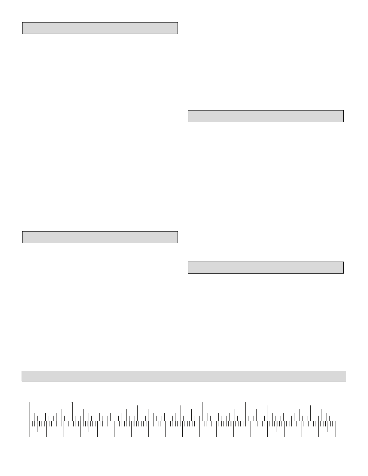
Inch Scale
0" 1" 2" 3" 4" 5" 6" 7"
0 10 20 30 40 50 60 70 80 90 100 110 120 130 140 150 160 170 180
Metric Scale
Page 4
4
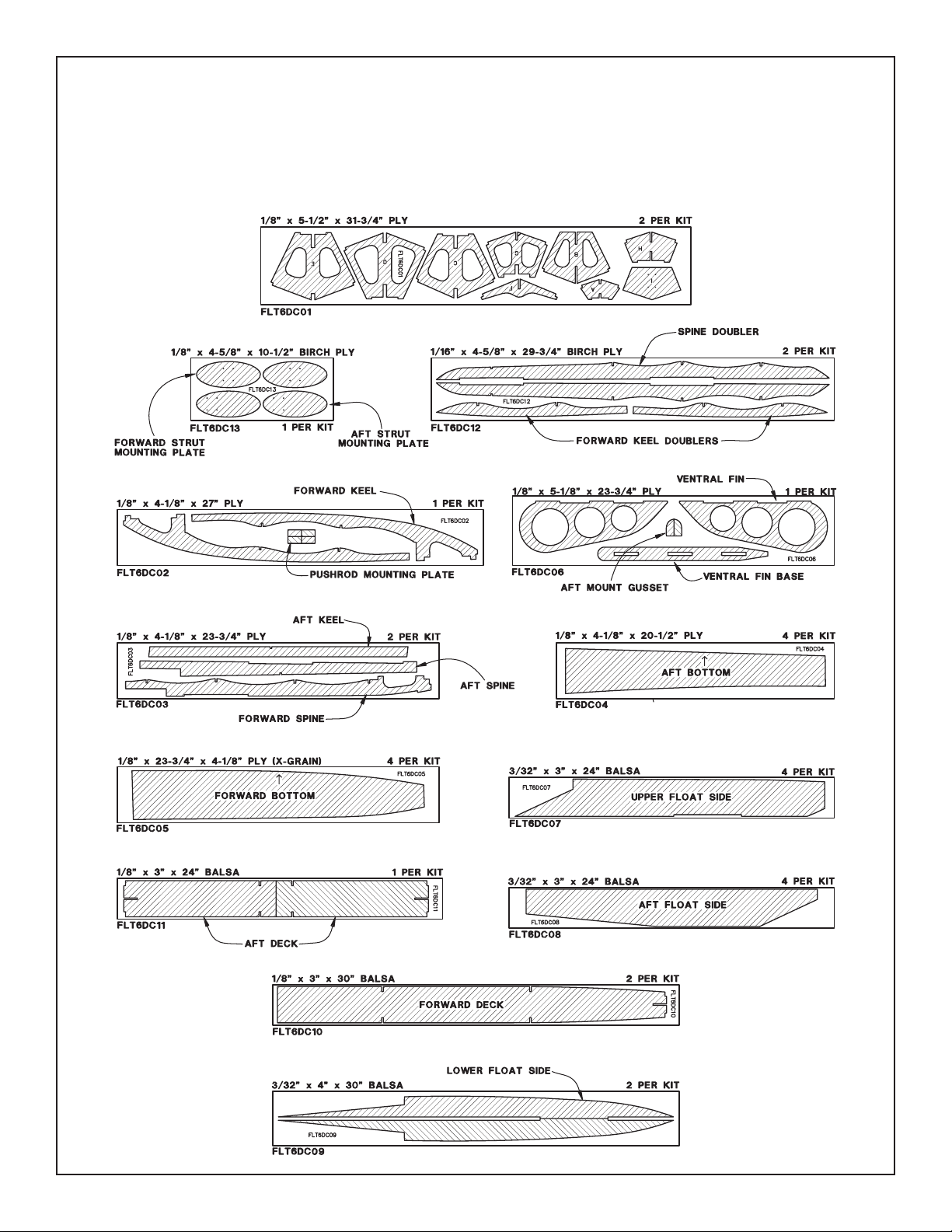
DIE-CUT PATTERNS
60 – SIZE
Page 5
5
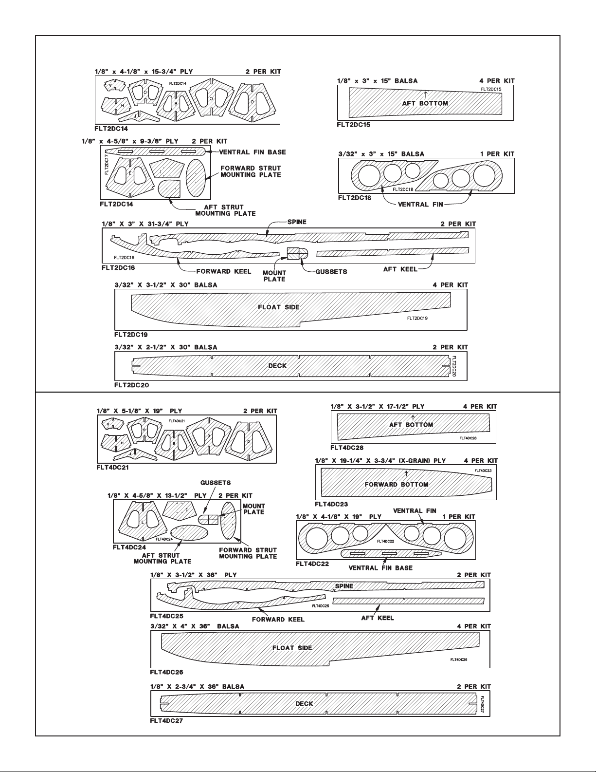
DIE-CUT PATTERNS
20 – SIZE
40 – SIZE
Page 6
If you are building the 20 or 40 Sports Floats, skip to
“Construction of 20, 40, 60 Floats” in the next column
on this page.
❏ 1. On a flat surface covered with wax paper, laminate the
die-cut 1/8" plywood forward and aft spine to one 1/16" diecut plywood spine doubler with 6-minute epoxy.Use weights
to hold the pieces together. Hint: Before the epoxy fully
cures, use a #11 blade to remove excess epoxy that gets into
the notches or oozes out from between the laminated pieces.
With Great Planes 6-minute Pro™Epoxy, this can be done
about 10 to 15 minutes after the epoxy has been mix ed.
❏ 2. Glue the other doubler to the other side of the
assembly with 6-minute epoxy.
❏ 1. Since the par ts are smaller, both forward keel
doublers may be laminated to the forward keel at the same
time. Mix up some 6-minute epoxy and apply to one side of
both die-cut 1/16" plywood forward keel doublers. Then
position a doubler on each side of the die-cut 1/8" plywood
forward keel. Hold the pieces together with weights.
Remove the excess epoxy before it fully cures.
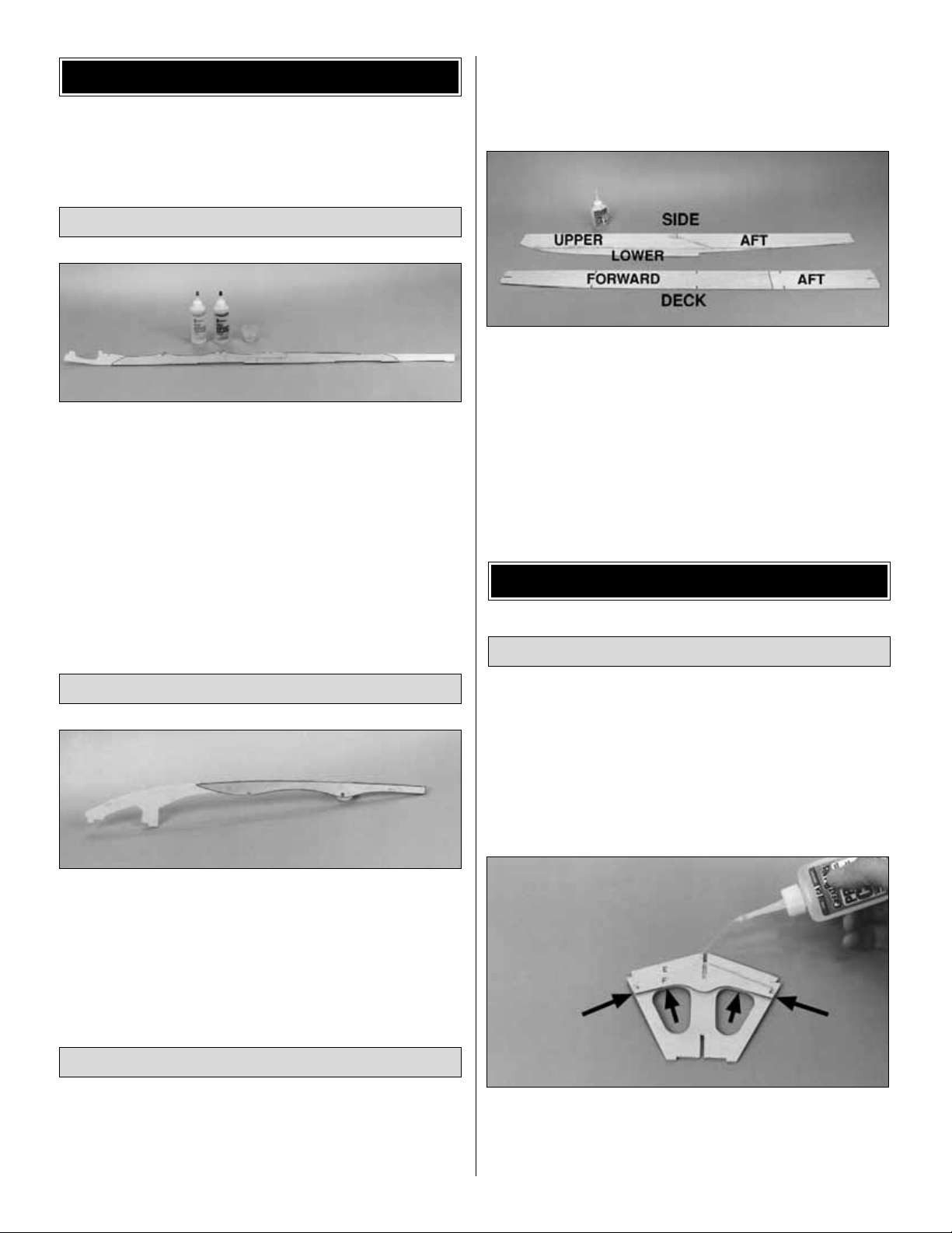
❏ 1. Trial fit the die-cut 3/32" balsa upper float side,
lower float side and aft float side. Make adjustments if
necessary. When satisfied with the fit, use thin CA to glue
the three pieces together over a building table covered with
waxed paper. After the CA has cured, use 150-grit
sandpaper and a sanding block to sand both sides of the
float side flat and smooth. Make another float side,
identical to the first.
❏ 2. Use thin CA to glue the die-cut balsa forward deck to
the aft deck. After the CA has cured, sand both sides of
the deck flat and smooth.
NOTE: If your float parts do not match each photo exactly,
it is because these instructions are written for all three
sizes. Regardless of which size Sport Float you are
building, the forward end of the float deck is the end
that tapers slightly.
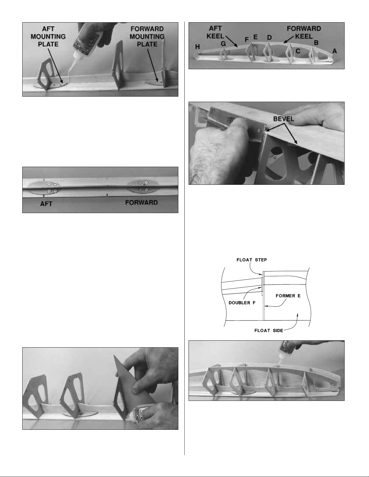
❏ 1. Drill 1/8" holes through the punch mar ks in the die-cut
1/8" plywood forward and aft strut mounting plates.
❏ 2. With the die-cut 1/8" plywood former doubler F
centered on the die-cut 1/8" plywood former E, align the
bottom edge of the doubler F with the lightening holes in
former E. Glue the pieces together with thin CA.
Framing
CONSTRUCTION OF 20, 40 & 60
Sides and Deck
Forward Keel
Spine
60 FLOATS PREASSEMBLY
6
Page 7
7
❏ 3. Tr ial fit the 1/8" plywood forward and aft strut mounting
plates, spine and formers C, D, E, and G to the balsa deck.
The formers are positioned in descending order with former A
in the front(see the photo to the right). NOTE: The aft str ut
mounting plate for the .40 and .60 Sport Float has the holes
towards the front. The aft strut mount plate for the .20 Sport
Float has a flat edge.Make sure all parts contact the deck, then
use thin CA to glue only the mounting plates to the deck.
❏ 4. Remove the formers and spine from the deck. Place a
scrap piece of wood under the deck, then using the holes in the
strut mounting plates as a guide, drill 1/8" holes through the
deck. Run a 4-40 x 1/2" bolt in and out of eight 4-40 blind nuts
to make sure the threads are “cleaned out.” Use a hammer to
lightly tap the 4-40 blind nuts into the plates, then add a few
drops of thin CA to the flange of each blind nut to secure them
in place. Do not get glue in the threads of the blind nuts.
Reinstall the spine and formers.Make sure all parts contact the
deck, then use thin CA to glue the spine to the deck.NOTE:Do
not glue the spine to the deck from former C forw ard.
❏ 5. Lay waxed paper over your flat building board and
position all the formers except A and I on the deck. Make
sure the notches in the formers fit all the way down to the
deck and make adjustments if necessary. Doubler F faces
the rear of the float.
❏ 6. Using a carpenter's square or a draftsman's triangle,
make sure each former is perpendicular to the deck and
use medium CA to glue them to the deck and spine.
❏ 7. Making sure the formers remain perpendicular to the
deck, trial fit, then use medium CA to glue the forward and
aft keel into the notches in the formers and the spine.
❏ 8.Remove the structure from the building board and use
a T-bar or flat sanding block with 150-grit sandpaper to
bevel the edges of the deck sheeting to match the formers.
❏ 9. Pin the assembly to your waxed paper-covered flat
building board.Trial fit, then sand a bevel to the top edge of
both die-cut balsa float sides to match the deck. Be sure
to make a
right
and a
left
side.
❏ 10. Align the step of one of the float sides with the aft
edge of former E. Use medium CA to glue the side to all
formers and the deck from former B to former H. Do not
glue the side to the deck forward of former B. Glue the
other side in the same manner. NOTE: The float side will
bow inward slightly at former G. This slight bow
is intentional.
Page 8

❏ 1. Cut the 3/16" x 3/16" aft stringers to length. Then
use thick CA to glue them to the formers only in the
notches of formers E, G, and H.
❏ 2. Remove the float from the building board once and for
all, then glue the sides to the aft stringers with thin CA.
Hint: hold the stringer to the sides with clothespins and
apply the thin CA from the
inside.
❏ 1.Install former A to the forward keel and spine, making
sure it is perpendicular. Then glue it in position with
medium CA.
❏ 2. Use medium CA to securely glue the deck to former
A, then the sides to the deck between formers A and B.
Inspect all glue joints and add CA where necessary. See
the following photo.
❏❏3. Cut a 3/16" x 3/16" forward stringer to fit in the
notches of formers E to A (do not attempt to bend the
stringer down to the notches in former A at this time). Use a
pen to make marks every 1/2" between formers C and A.
❏❏4.Take the stringer out of the notches in the float and
use a razor saw to cut a 1/16" deep notch at every mark
you just made. Hint: use a piece of 1/8" thick scrap
plywood as a gauge so the saw will cut every notch the
same depth.
❏❏5. With the notches in the forward stringer facing the
deck, first glue the stringer to the formers only with
medium CA. Then glue the side to the forward stringer in
the same manner that you glued the side to the
rear stringer.
❏ 6. Add the other forward stringer in the same manner.
The photo at step 2 (next page) shows the stringers glued
to the sides.
Forward Stringers
Aft Stringers
8
Page 9

❏ 1. To provide a good glue joint for the bottom sheeting,
use a sanding block and 150-grit sandpaper to trim the side
sheeting down to the side stringers and to bevel the
forward and aft keel to the same angle as the formers. Be
sure to maintain a smooth curve in the float sides when
sanding. Use the stringers as a guide.
❏ 2. It has been our experience that ballast is required in
order to move the center of gravity forward when the floats
are mounted on the airplane. This can easily be
accomplished by using 6-minute epoxy to glue the weight
inside the floats just behind the front former A. Spread
epoxy over and around the lead weights to prevent them
from coming loose. We suggest 1 oz. inside each 20 float,
1-1/2 oz. inside each 40 float and 2 oz. inside each 60 float.
❏ 1. Tr ial fit the die-cut 1/8" plywood aft bottom sheets.
Note: The 20 floats use die-cut 1/8" balsa aft bottom
sheets. The straight edge goes toward the center and
should be placed so it covers half of the keel. Make
adjustments if necessary and bevel the edges of the aft
bottom sheets that contact each other in the center.
Note: An embossed arrow is provided on the .40 and .60
aft float bottoms as an aid to alignment.
❏ 2. Working on your flat building board, use thick CA to
glue one aft bottom sheet to the aft side stringer and
formers only. Do not apply CA to the aft keel at this time.
❏ 3. Glue the other aft bottom sheet in position, applying
thick CA to the side stringers, formers and aft keel, gluing
both aft sheets to the keel and each other simultaneously.
❏ 1.To prepare the forward bottom sheets for one float,
cut ten 3-1/2" pieces from a 1/8" x 3" x 30" balsa sheet,
then make two cross-grain sheets by gluing 5 pieces
together.
Carefully
sand the sheets flat using a sanding
block and 150-grit sandpaper.
20 Floats Only
If you are building the 20 Sport Floats, follow these
steps first to make the bottom forward sheeting.
Otherwise, skip these three steps and add the
bottom forward sheeting now.
Forward Bottom Sheeting
Aft Bottom Sheeting
Prepare for Sheeting
9
Page 10

Add the forward bottom sheeting in the same manner as
the aft bottom sheeting:
❏ 1. On the 40 and 60 die-cut 1/8" plywood forward
bottom sheets, there is an arrow indicating the inboard
edge of each sheet (although one of the sheets on each
float will have to be flipped over).Trial fit the two sheets and
bevel the inboard edges that contact each other for a good
glue joint.
❏ 2. Use thick CA to glue one of the sheets to the side
stringer and formers only – do not apply CA to the
forward keel.
❏ 3. Apply thick CA to the side stringer, formers and keel
to glue the second sheet in position and both sheets to the
keel and each other simultaneously. Use the embossed
arrows to aid in final alignment.
❏ 4. Referring to the sketch, “rough sand” the entire float
with a sanding block and 150-grit sandpaper, blending the
sides to the deck and the bottoms to the side. Sand all
sheeting and stringers flush with formers A and H.
❏ 1.Glue the balsa nose block to former A with thick CA.
❏ 2.Carve the nose block to the approximate shape, then
use a sanding block and 150-grit sandpaper to blend the
block to the sides, deck and bottom.
❏ 3. Finish sand the nose block by rounding the front and
slightly
rounding the corners.
Nose Block and Finishing
❏ 3. Carefully cut the strips along the line. Mark the
inboard edge of each bottom sheet.
❏ 2. Accurately cut out the 20 float forward bottom
sheeting template from the center sheet in the manual,
then trace the outline on each sheet. Hint: Tape the
template to the sheet at the front and the rear.
10
Page 11

❏ 4. Use thick CA to glue on the die-cut 1/8" plywood
transom plate I so the punch marks are visible. Sand the
edges to blend with the sides, top and bottom.
❏ 5. Dr ill a 1/16" hole through each punch mark in the
transom plate on only one of the floats. This is now the
right float to which the rudder will be mounted.
❏ 6. Fill any nicks, scratches, or seams with HobbyLite
™
filler. After the filler has cured, final sand the entire float
with a sanding block and 220-grit, then 320-grit, then 400grit sandpaper.
There are two ways you can cover your floats.You can use
Top Flite®MonoKote®covering or fiberglass cloth and resin
with paint. “Glassing” seals the wood grain and is required
if you wish to paint the floats. This can be an involved,
messy project but yields a highly durable finish. MonoKote
covering is the quicker, easier method and provides a
surprisingly durable finish as well. In fact, our prototype 60
floats mounted on our Great Planes J-3 Cub 60 are
covered with MonoKote film and were really put to the test!
Following are instructions for both covering methods.
❏ 1. Seal all seams (except around the nose block) with
1/2" wide strips of MonoKote film. Iron these strips down
with a hot iron for a good seal.
❏ 2.Continue to cover the float, in the following sequence:
A.Transom
B.Deck
C.Sides
D. Aft bottom
E. Forward bottom
All pieces should overlap at the nose. Iron the large pieces
of covering down by starting in the center, pulling and
working out to the edges.
❏ 3. You can enhance realism by adding panel lines and
rivets with a fine-point indelible pen, creating a propeller
arc warning line (red) from MonoKote covering, and making
the flat black walkways (on right float only) from 400-grit
wet/dry sandpaper.
Apply the glass cloth in this order:
1.Transom
2. Deck and both sides in one piece
3. Aft bottom
4. Forward Bottom
❏ 1. Cut a piece of 3/4 oz. (Lightweight) glass cloth 1/2"
larger than the transom all the way around.
Glass Cloth and Resin
MonoKote®Covering
Covering Method
COVERING
11
Page 12

❏ 2. Mix up 1 oz. of finishing resin following the
instructions provided in the Great Planes Pro™Epoxy
Finishing Resin kit. Use an epoxy brush to liberally coat the
transom of the float.
❏ 3. Place the cloth on the resin-coated transom, then
brush the resin through the cloth, removing excess resin
from the center to the edges. Be sure to allow the excess
glass cloth to wrap around the top, sides and bottom of the
float. Some expert modelers squeegee the excess resin off
with a business card or expired plastic credit card. Let the
transom fully cure.Then with a sanding block and fresh 220
grit sandpaper, feather the glass cloth into the float top,
sides and bottom.
❏ 4.Apply glass cloth and resin to the deck and sides (one
piece).The cloth should wrap around the bottom 1/4". Hint:
If you cut and position the cloth with the weave running at
45 degrees to the float, the cloth will more readily go
around the sharp bottom corners.Try it!
Another Hint: Build a simple stand to hold the float while you
apply the resin and cloth to the deck and sides. Let the deck
and sides fully cure.Then with a sanding block and fresh 220
grit sandpaper, f eather the glass cloth into the bottoms .
❏ 5. Following the same procedure outlined above, apply
glass cloth to the bottoms and step. The cloth needs to
overlap the sides 1/4" as shown in the sketch.
❏ 6. Lightly sand the entire float with 320-grit sandpaper
being careful not to cut into the glass cloth. Mix up a
2 oz. batch of resin and use a regular camel hair or similar
1" wide paint brush to brush on another coat of resin over
the entire float. For ease of handling, you may do the top
and sides first, then the bottom. If you work quickly you can
save the paint brush by cleaning it with alcohol before the
resin begins to thicken.
❏ 7. Carefully sand the entire float with 360-grit sandpaper
and a sanding block, being careful not to sand through
to the cloth. Note: See step 2 under Pushrod Hookup on
page 17 and glue the 1/8" plywood mount block to the deck
after you apply the glass cloth. It is not necessary to cover
the mount block with glass cloth but you should apply resin
over the bare wood. The float is now ready for a coat of
primer.If you have sanded through the second coat of resin
into the cloth, you will have to apply a third coat of resin in
those areas.
❏ 8. Apply a coat of primer to the floats. Many expert
modelers have established their favorite brand of paint and
painting methods, but our recommendation is Top Flite
LustreKote Primer. Over glass cloth and resin, one coat of
primer may be sufficient but two coats may be required.You
may dry sand between coats of primer and paint but wet
sanding is preferred – be sure to plug the holes in the deck
for the strut mounts so water does not get inside and do
not sand through the glass cloth.
❏ 9 . Paint the floats. Again, our recommendation is Top
Flite LustreKote.If you have a good base coat of primer you
may need only one coat of color.
Before you continue, take a break from building and
study the following information to be sure you
understand the positioning of the floats in relation to
the wing and fuselage.
While the following instructions show the Sport Floats on
Great Planes Piper Cubs, there are general tips and
guidelines that apply to all models which will insure proper
handling characteristics in the water and good landing and
takeoff tendencies.
POSITIONING OF FLOATS
12
Page 13

The relationship between the “step” on the floats and the
center of gravity on the model is important. First, the floats
should be mounted on the model so the step is positioned
as detailed in the “Step Sketch” for your particular model.
Then, when the floats are mounted on the model, move the
C.G. slightly forward as listed below. Although you may
have added the recommended ballast inside the front of
the float, in some cases a little more ballast may be
required on the model.
For 60-size floats: Move the CG (Balance point) 1/2"
ahead of the manufacturers recommended CG.
For 40-size floats: Move the CG (Balance point) 3/8"
ahead of the manufacturers recommended CG.
For 20-size floats: Move the CG (Balance point) 9/32"
ahead of the manufacturers recommended CG.
Another important relationship between the wing and the
floats is the relative “angle of attack.’’ With a virtually flat
bottom wing such as a Piper Cub, the deck of the floats
should be parallel to the bottom of the wing. Since the Cub
does not have a truly flat wing, this yields a slight positive
wing incidence in relation to the floats, and the airplane will
tend to rise off the water at the correct time. If you have a
model with a symmetrical wing, the wing incidence in
relation to the float deck should be positive 1-1/2 degrees.
Finally, each float should be set so that it is parallel to the
centerline of the fuselage.
❏ 1. You must have a solid mounting location on the
fuselage bottom for the aft float strut. If you have not
previously built in the aft float mount plate to the bottom
of your fuselage, follow the instructions below.
A. For greatest strength, it is preferred that the 1/8”
plywood aft float mount plate (included with the float
kit) be positioned under a former.The location of the aft
float mount plate is determined by the aft strut (included
with the float kit) which can be custom bent. On the
Great Planes Cub 60 and Cub 20, the location of the aft
float mount plate is shown on the plan included with the
model. To locate the former, push a pin through the
bottom of the fuselage until you find it.
B. Remove a section of the bottom sheeting, centered
over the former, wide enough to accept the aft float
mount plate.
Prepare Your Airplane to Accept
the Floats
13
Page 14

❏ 2. Use the landing gear included with your airplane for
the front struts unless you are building a Great Planes
Cub 60. For the Cub 60, you will use the front landing gear
strut and cross brace provided with the floats. For some
models, the front landing gear mounting location on the
fuselage may have to be moved to allow the step in the
float to be placed according to the recommendations.
❏ 1. Remove any oily residue from the wire struts by
wiping them with alcohol. Roughen the area to be soldered
with 150-grit sandpaper.
❏ 2. Silver solder, such as Great Planes Silver Solder
(GPMR8070), is highly recommended.
❏ 3.For soldering the heavy gauge wire struts, higher heat
is required than for normal electrical soldering. A torch is
recommended but some heavy duty soldering irons may
work as well. The higher the temperature of the heating
source applied to the joint, the quicker the solder will flow
and the less time the wire will have to draw heat away from
the area.
❏ 4. Avoid a “cold” solder joint which will not have the
shiny appearance of a proper solder joint. A cold joint may
be caused by disturbing the pieces before the molten
solder has solidified or by a joint that never had enough
heat to let the solder flow.
❏ 5. Read the instr uctions provided by the manufacturer of
the solder.
❏ 1. Match the shor ter front strut with the front cross
brace and the taller rear strut with the rear cross-brace.
The matching struts and cross-braces are the ones that fit
together the best. Note: If you are mounting the floats on a
model other than the Great Planes Cub 60, you may use
the main landing gear included with your model to mount
the front of the floats, and the rear struts included with this
kit to mount the rear of the floats.You may have to relocate
your main landing gear in order to place the step on the
floats at the required position.
❏ 2. Wrap each joint neatly and tightly with the
reinforcement wire.
A. For ease of handling, apply thin CA to the joint to
temporarily hold the pieces together.
Solder the Cross-Braces
Notes about Soldering
60 FLO
ATS ONLY
This section pertains to the 60 Sport Floats only. If
you are building the 20 or 40 Sport Floats, skip to
the “20 And 40 Floats Only”section now.
60 FLOATS ONLY
C. Use 30-minute epoxy to glue the die-cut 1/8" plywood
float mount plate gussets to the fuselage side and
former. Note: The bottom of the gussets may have to be
beveled so they are flush with the bottom of the
fuselage side.
D. Tr ial fit the aft float mount plate, cut it to the correct
length, then use 30-minute epoxy to securely glue it in
position.When the epoxy has cured, use a sanding block
and 150-grit sandpaper to blend the aft float mount plate
to match the contour of the fuselage bottom. Cover the
bare wood to match you model.
14
Page 15

B. Cut a 26" piece of wire and make a sharp bend about
3/8" from the end.
C. Place the wire between the braces and begin tightly
wrapping the wire.
D. When complete, route the excess wire through the wire
wrap and pull it tight.Cut off the excess wire.
❏ 3. Heat the joint, apply a few drops of acid flux, then
feed in the silver solder. A proper solder joint looks like the
one in the photo – not a “dry” solder joint nor a big hideous
glob.Solder all four joints.
❏ 1. Cut the nylon bearing mounts into two pieces, then
enlarge them with a #12 (or 13/64") drill bit. Mount the
bearings to the floats with 4-40 x 1/2" screws.
❏ 2. Temporarily join the floats to the struts by inserting
them into the bearing mounts. Use a felt tip pen to mark the
location of the diagonal braces as indicated in the sketch.
❏ 3. Trial fit the floats and struts on your model before
soldering the diagonal braces.The spacing and angle of the
struts is determined by placement of the diagonal braces.
❏ 4. Wrap, then solder the diagonal braces to the struts.
Lay a damp cloth under each solder joint as you proceed to
avoid damaging your finish.Test fit the floats to your model
and make adjustments if necessary.
Mount the Struts to the Floats and
Solder the Diagonal Braces
15
Page 16

❏ 5.The completed struts may be painted. First remove all
residue with alcohol, thoroughly sand with 400-grit
sandpaper, then clean again with alcohol or thinner
before painting.
❏ 1. Mount the struts to the floats with 3/16" wheel
collars and 6-32 machine screws. Then turn the
fuselage upside-down and place the struts on the model
with the “step” in the floats positioned according to
the recommendations.
❏ 2. Place three 5/32" nylon hump straps, evenly spaced,
on each strut and mark the screw hole locations. Dr ill a
3/32" hole at each mark, then fasten the floats to the
fuselage with 12 #4 x 1/2" sheet metal screws.
If you are building the 60 floats, skip to “Build the water
rudder” on page 17.
❏ 1. Cut the nylon bearing mounts into two pieces and
mount them to the floats with 4-40 x 1/2" screws. If your
front landing gear is 3/16" diameter wire, you will have to
drill out the front bearing mounts with a 13/64" or #12 drill
bit. See the following photo for proper bearing
mount placement.
❏ 2.Temporarily join the floats to the str uts with the 5/32"
wheel collars.
The following instructions show the Great Planes J-3 Cub
20 and 40. Use the instructions, sketches and photographs
as a general guide if you are mounting the 20 or 40 Sport
Floats to a different model.
❏ 1. Turn the fuselage upside-down and place the front
struts in the torque blocks in the fuselage and the lay rear
struts on the aft strut mount plate.
❏ 2. Mount the front struts to the fuselage as they were
with the conventional landing gear, then place two nylon
5/32" hump straps on the rear strut 3/8" from the fuselage
side. Mark the strap locations. Note: The 40 Spor t Floats
require a third hump strap in the center of the rear strut.
❏ 3. Drill 1/16" holes at each mar k. Then fasten the float
struts to the fuselage with #2 x 3/8 sheet metal screws.
❏ 4.The completed struts may be painted. First remove all
residue with alcohol, thoroughly sand with 400-grit
sandpaper, then clean again with alcohol or thinner
before painting.
Mount the Floats to the Airplane
Mount the Struts to the Floats
20 AND 40 FLOATS ONLY
Mount the 60 Floats to the Airplane
16
Page 17

❏ 1. Install the wheel collar and the brass tube bearing
on the rudder shaft. Use the 4-40 x 1/4" socket head cap
screw and 4-40 lock nut to mount the rudder to the
rudder bracket, then silver solder the rudder bracket to the
rudder shaft. Do not solder the brass tube to the rudder
shaft. Note: The 60 and 40 floats require a brass tube,
wheel collar, then another brass tube. Refer to the sketch
for each assembly.
❏ 2. Lock the wheel collar so the rudder shaft cannot slide
up and down in the brass tube. Note: on the 60 and 40
rudder, lock the wheel collar so the rudder shaft cannot
slide up and down on the bottom brass tube.
❏ 3. Cut the threaded portion of the rudder shaft so 3/4" of
the thread remains, then screw on the nylon swivel 1/8"
past the end.
❏ 4. Loosely install the rudder on the right float with two flat
straps, two 1/8" hump straps and four #2 x 3/8" sheet metal
screws. Adjust the bottom of the r udder bracket so it is even
with the bottom of the transom, then tighten the screws.
Note: Do not overtighten the 4-40 screw and nut that secures
the rudder to the bracket. The rudder must be able to pivot
upward in case it hits a foreign object in the water – or
the shore.
❏ 1. With the floats mounted to the model, solder a
threaded coupler to one end of the braided cable, then
thread on the nylon swivel clevis. Slide the cable into the
pushrod guide tube.
❏ 2. Position a die-cut 1/8" mount plate on the deck of the
float 3" from the rear. Remove the covering from
underneath, then glue it in position. Hint: Cover the mount
plate to match your floats before you glue it in place.
Pushrod Hookup
Build the Water Rudder
ALL MODELS
17
Page 18

❏ 3. Drill 1/16" holes in the mount plate. Then use #2 x
3/8" sheet metal screws to fasten a 1/8" hump strap and
outer pushrod tube with pushrod. Connect the swivel clevis
to the swivel on the rudder shaft.
❏ 4.Mount an additional control horn (included with float
kit) on the right side of the rudder.
❏ 5. Cut off one side of the
base
from two 1/8" nylon hump
straps as shown in the sketch.
❏ 6 . Hold the outer pushrod tube and cable along the
bottom of the fuselage in a position that will provide a gentle
loop from the float to the rudder as shown in the photo.
Where the pushrod tube meets the fuselage, remove a
section of covering and install another die-cut plate.
❏ 7.Fasten the guide tube to the aft strut with a nylon tie.
❏ 8. Drill a 1/16" hole and secure the cable guide tube to
the mount plate with one of the cut-off hump straps and
#2 x 3/8" sheet metal screws.
20 - 40 Floats only
After performing steps A and B, continue with step 8.
A. Screw a threaded coupler to a nylon clevis. Then
temporarily fasten the clevis and coupler to the rudder
horn. Holding both the water rudder on the float and the
rudder on the model in a neutral position, determine the
length of the pushrod cable, remove it from the guide tube,
then cut it to length. Hint: A Great Planes cut-off wheel
(GPMR8200) works great for cutting cable like this without
fraying the end.Cut the guide tube to a length so that it will
not interfere with the threaded coupler when it is soldered
onto the cable. There must be enough clearance to allow
the cable to slide freely.
Connect the Rudder
18
Page 19

Note: Before reinstalling the cable into the guide, apply a
light coat of oil or petroleum jelly to the cable to prevent
future corrosion.
B.Remove the threaded coupler from the nylon clevis, slide
the cable back into the outer pushrod tube, then solder the
cable to the coupler. Thread the clevis back onto the
coupler. Then attach it to the rudder horn. Make final
adjustments by screwing or unscrewing the nylon clevis at
either end of the cable.
60 Floats Only
After performing steps A and B, continue with step 8.
A. Screw a nylon clevis to the .074" x 12" threaded rod.
Then temporarily fasten the clevis to the rudder horn.
Holding the water rudder on the float and the rudder on the
airplane in a neutral position, determine where the threaded
rod and the cable will be joined with the coupling sleeve.
Then cut the rod to length. Remove the cable from the guide
tube, and then cut the cable to length. Hint: A Great Planes
cut-off wheel (GPMR8200) works well for cutting cable like
this without fraying the end. Cut the guide tube to a length
that will not interfere with the split coupler when it is
soldered onto the cable and the cable moves in and out.
Note: Before reinstalling the cable into the guide, apply a
light coat of oil or petroleum jelly to the cable to prevent
future corrosion.
B. Slide the cable back into the guide tube. Then join the
threaded rod to the cable by soldering the coupling sleeve
to both pieces. Make final adjustments by screwing or
unscrewing the nylon clevis at either end of the cable.
❏ 8. Mount another 1/8" plywood mount plate and the
other cut hump strap near the rear of the guide tube.
❏ 9. Test the actuation of the water rudder on the floats.
The water rudder and the rudder on the model must both
be neutral and move in the same direction.
The purpose of the ventral fin is to increase yaw stability.
Some models may be flown successfully without the ventral
fin, but we strongly recommend that you add the ventral fin
to your airplane when flying with Great Planes Sport Floats.
❏ 1. Laminate the die-cut 3/32" balsa ventral fins with
6-minute epoxy. Note: The 60 ventral fin is two pieces of
die-cut 1/8" plywood. Hint: Clamp the ventral fins together
while the epoxy cures by laying weights on top of them over
a flat work surface covered with wax paper. After the glue
has cured, use a sanding block and 150-grit sandpaper to
sand the ventral fin flat, remove any excess glue, and round
the edges.Final sand with 320 to 400-grit sandpaper.
❏ 2. Making sure the ventral fin is perpendicular to the
die-cut 1/8" plywood ventral fin base, glue the pieces
together with medium CA.Then glue the 1/4" balsa triangle
stock to the fin and base.
❏ 3. Cover the assembled ventral fin to match your model.
Then mount it to the bottom of the fuselage right on the
centerline of the fuselage. The suggested mounting method
is double-sided foam mounting tape. An alternate mounting
method would be to use #2 x 3/8" sheet metal screws.If you
use screws, 1/8" plywood blocks should be glued to the
inside of the bottom sheeting where the screws are located.
❏ 4. Balance your airplane again, after adding the ventral fin.
VENTRAL FIN
19
Page 20

❏ 1. The set screws on the wheel collars should be
secured with liquid thread-locking compound. On the 60
floats, it is recommended that a small flat spot be filed on
each strut where the set screw locks.
❏ 2. Plastic “splash strips” that protrude below each inner
float side by 1/2" may be added if too much water gets
splashed up onto the propeller – you'll be surprised at the
damage water can do to the propeller. This is highly
recommended for the 20 floats and can be fastened directly
to the covering with double-sided foam tape or Pacer brand
ZAP-A-DAP-A-GOO cement. A template is provided in the
middle of the manual for the float splash strips.They may
be cut from .06" ABS, styrene or other plastic sheet.
Salt water flyers should pay special attention
to these instructions.
❏ 1. Where possible, seal pushrod exits and the receiver
switch or other openings with petroleum jelly or similar.
❏ 2. Seal screw holes with clear RTV silicone. This
includes screws on the floats that hold on the water rudder,
strut mount bearings, and hump straps, as well as the
screw holes that hold the straps on the fuselage, etc.
❏ 3. Lightly oil the moving parts of the r udder and the
cable inside the outer pushrod tube.
❏ 4. Make sure you have a good seal between the wing
and the fuselage. If not, make a “gasket” out of RTV
silicone or foam wing tape.
❏ 5.Enclose the receiver and battery in plastic bags, then
wrap with rubber bands.
Before setting the model in the water, be sure the water
rudder on the float is extended. A reliable, slow idle is a
must – unless you can swim well! First flight attempts with
floats should be reserved for relatively calm days when the
water is not so choppy. Practice taxiing around in the water
to learn the handling characteristics and see if you have
built in enough throw on the water rudder. Make
adjustments if required. During taxiing, hold “up”elevator to
keep the nose of the airplane high and the propeller out of
the water. Always takeoff into the wind. Gently add throttle
and gradually release some of the up elevator as the speed
increases. Just like the model takes off the ground, when it
has enough speed it will lift into the air – don't force it off.
Continue a gradual, conservative climbout until you are at
an altitude where you are comfortable making the
downwind turn.
Learn the flight characteristics of the model with the added
weight and drag of the floats. A model that was not
marginal on power to begin with will do fine – you'll
probably be surprised. Our Cub 60 with the O.S. 91
Surpass while not overpowered, does have plenty of
reserve and is perfectly capable of loops, rolls, stall turns
and inverted flight with the Sport Floats.
Landing approach is the same on water as it is on land.
Touch down slow to avoid bouncing the airplane off the
water back into the air.“Crabbing” is a great technique used
to bleed off airspeed during approach of “floater”models like
a Cub. This is done by applying a balance of rudder and
opposite aileron to make the airplane fly “sideways.” The
path of the model is “down the runway” while the nose is
pointing off to one side. Just before the floats contact the
water, release the rudder and opposite aileron.
Although it is difficult to do, the model can contact the water at
such an angle as to allow the tips of the floats to “catch,” thus
flipping the model immediately. Avoid letting the floats contact
the water at anything but a le v el or slightly positiv e attitude .
Be considerate to others at the lake and
enjoy your Great Planes Sport Floats!
FLYING
WATERPROOFING
BEFORE GOING TO THE LAKE
Page 21

 Loading...