

Page 1
™
Power Meter with Balancing
INSTRUCTION MANUAL
INSTRUCTIONS
The PowerMatch meter is a perfect device for matching electronic
components to optimize electric fl ight performance and satisfaction.
An easy-to-read 216 LCD, easy menus, and high quality input/
output connections make it simple to measure cell voltages, pack
voltages, current, power, remaining battery capacity, and more!
Match propellers to motors for optimum performance. Match battery
packs to motors. Determine system loads. It even includes a built-in
balancer which is perfect for conditioning up to 7S LiPo or LiFe
packs! The PowerMatch meter is an extremely handy and useful
tool for the workbench or fl ight line.
It is strongly recommended to completely read
this manual before use! Damage resulting from
misuse or modifi cation will void your warranty.
GPMM3220 v2Entire Contents © 2015 Hobbico,® Inc. All rights reserved.
Page 2

SPECIFICATIONS
Battery Types
LiPo, LiFe, Li-Ion, NiCd,
NiMH with auto-detection
Voltage Measurement Range
4– 8 NiCd, NiMH cells
2–7 LiPo, LiFe, Li-Ion cells
4.0 – 30.0V absolute maximum range
Lithium Balancing Accuracy
Lithium Balancing Connection
10mV per cell
ElectriFly compatible,
FlightPower
Lithium Max. Node Current
Maximum Rated Current
Maximum Capacity Displayed
Auto-Off
Protection Systems
180mA max.
80A instantaneous
65,000mAh (65.0Ah)
After 30 seconds of inactivity
Reverse polarity protection,
Low LiPo voltage alert
with auto-shut down
Case Size
Weight
10 0 × 65 × 25mm (3.9 × 2.6 × 1.0")
127.8g (4.5 oz.)
SPECIAL FEATURES and FUNCTIONS
®
adapters included
Battery Checker Mode recognizes the number of cells
in a pack and measures cell and pack voltages
Cell Balancer Mode balances up to 7S lithium battery
packs
Power Checker Mode can display measured power,
current, battery voltage, and used capacity while under
loads up to 80 amps instantaneous
Star Plug® male on input, Star Plug female on the
output, with built-in radio battery jack and balancing
connection
2
Page 3

IMPORTANT WARNINGS
Disconnect the battery from the meter immediately
if the meter or battery become hot!! Allow the meter
and battery to cool down before reconnecting.
NEVER allow water, moisture or foreign objects into the meter.
NEVER block the air intake holes or fan as this could cause the
meter to overheat.
NEVER attempt to use batteries with more cells or total voltage than
listed in the specifi cations.
NEVER attempt to pass more current/power through the meter than
listed in the specifi cations.
ALWAYS disconnect the battery from the meter when not in use.
ALWAYS keep out of reach of children.
GLOSSARY OF TERMS
Amps (A): The unit of measure for charge or discharge current.
Milli-amps (mA): A unit of measure for current, being amps (A)
multiplied by 1000 and listed as “mA”. So 2.5A is the same as 2500 mA
(2.5 1000). Or, to convert mA to amps, divide the mA number by
1000. So 25mA is the same as 0.025A (25 divided by 1000).
Capacity, milli-amp hours (mAh), and amp-hours (Ah): Charge
energy stored by a battery is called capacity, which is defi ned as
how much current a battery can supply in one hour of time. Most
hobby batteries are rated for capacity in “mAh” or milli-amp
hours. A 650mAh battery can deliver 650mA of current for one hour
(650 mA 1hr = 650 mAh). A 3200mAh battery can deliver 3200mA
(3.2A) of current for one hour (3200mA 1hr = 3200mAh), etc. Very
large batteries, such as lead-acid fi eld batteries, are usually rated in
“Ah” or amp-hours. A “12V 7A” fi eld battery can deliver 7 amps of
current for one hour (7A 1hr = 7Ah).
3
Page 4
INPUT POWER – CONNECTION, PROTECTIONS & LIMITATIONS
The meter draws input power
from the battery that is
connected for measurement.
The meter will automatically
enter a sleep mode if no
commands are given within
30 seconds, but note that
power will still remain active
in the meter during this time.
Simply press ENTER to reactivate the meter.
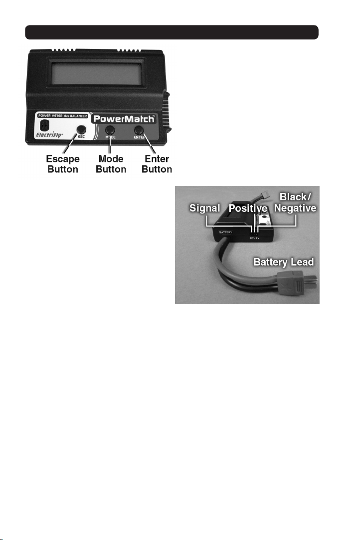
The BATTERY lead on the
left side of the meter is used
for connecting large power
batteries. Lithium packs up to
7S can be used, including LiPo
batteries rated at 25.9V, LiFe
packs up to 23.1V, and Li-Ion
packs up to 25.2V.
The RX/TX battery jack
can accept NiCd and NiMH
batteries having a nominal rating of up to 9.6V, with a universal or
Futaba® J type connector.
The PowerMatch meter can handle up to 80 amps of current
instantaneously, and measure capacity up to 65Ah (65,000mAh).
Passing more than 50 amps through the meter continuously for
over 2 minutes will cause heat to generate and cause readings to
become less accurate. Do not exceed the maximum rated current or
voltage handling capabilities of the meter.
4
Page 5
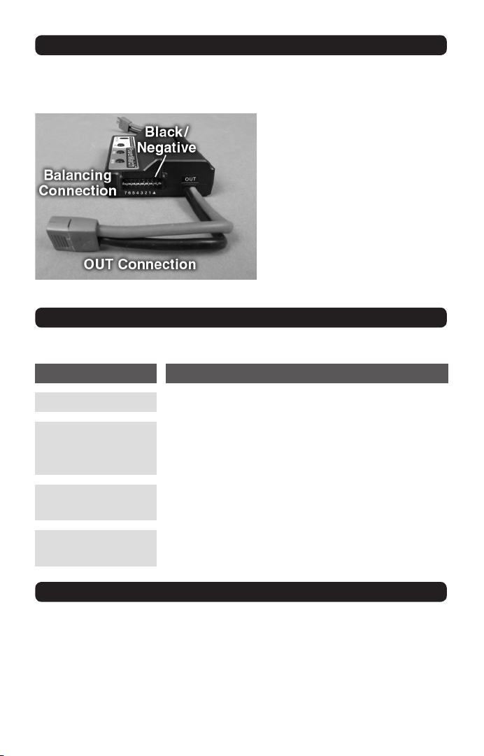
OUTPUT and BALANCING CONNECTIONS
The OUT connection is located on the right side of the meter, and
includes a Star Plug female connector.
A balancing connection is
located on the right side of
the meter, capable of handling 2S-7S lithium batteries. Terminal spacings are
compatible with ElectriFly
style balancing plugs. An
adapter is included for connection of FlightPower® and
Thunder Power™ battery
balancing plugs.
MENU STRUCTURE
The PowerMatch meter has four different operational modes:
MODE OPERATION
BATTERY CHECKER
Shows the present status of the battery.
Determines how well cells in a lithium battery
CELL BALANCER
are balanced, and balancing can be initiated
through this mode.
POWER CHECKER
USER SETTING
For measuring and storing various types of
data measured under loaded conditions.
For setting low voltage detection level
for lithium batteries.
BATTERY CHECKER MODE – LiPo, LiFe, Li-Ion BATTERIES
This mode is used to measure the present status of a lithium
battery, showing the number of cells in the battery, static battery
voltage, capacity remaining, highest cell voltage, lowest cell
voltage, gap in voltage between the highest and lowest cell, and
individual cell voltages.
5
Page 6
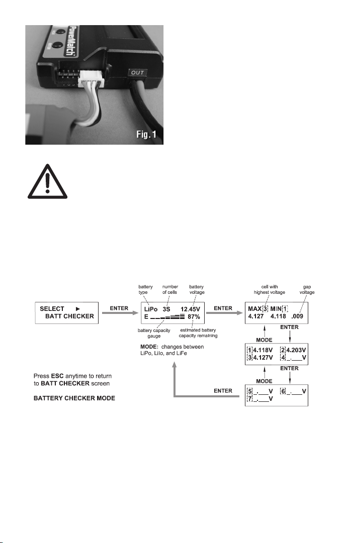
1. Connect the 2S-7S lithium
battery to PowerMatch’s balancing
terminals. Make sure the negative
wire of the battery’s balancing
plug is connected to the terminal
at far right as shown in Fig. 1. Do
NOT connect the lithium battery’s
main lead to the meter.
WARNING! NEVER allow the positive and negative
output connections to touch while a battery is
connected to the input. Failure to do so could result
in permanent damage to the battery and/or the meter
and void your warranty.
2. The BATT CHECKER screen should appear automatically. If not,
press MODE until this screen appears.
3. Press ENTER to view this function.
Fig. 2
4. The battery status screen will appear, showing the battery type,
number of cells, total pack voltage, and estimated amount of
capacity remaining in the battery.
5. Press MODE as needed to change the battery type shown on this
screen, from Li-Ion to LiFe to LiPo. It’s important to select the proper
battery type so PowerMatch can accurately display data.
6
Page 7

6. Press ENTER to view the cell with highest “MAX” voltage, cell
with the lowest “MIN” voltage, and the voltage difference or “gap”
between those two cells. The cell numbers will show directly next to
“MAX” or “MIN”.
7. Press ENTER to see voltages for cells 1-4. Press ENTER again
to see voltages for cells 5-7. Press MODE to move to the previous
screen as show in Fig. 2.
Press ESC at any time to return to the main BATT CHECKER
screen.
BATTERY CHECKER MODE – NiCd & NiMH RADIO BATTERIES
This mode can also be used to measure the current status of a
nickel-cadmium (NiCd) or nickel-metal hydride (NiMH) transmitter
or receiver battery.
1. Connect the 4-8 cell NiCd or
NiMH battery’s universal or
Futaba-J plug to the meter’s Rx/
Tx jack. Make sure the battery’s
negative wire (black or brown) is
on the right as shown in Fig. 3.
2. The BATT CHECKER screen
should appear automatically. If
another function appears, press
MODE until this screen appears.
3. Press ENTER to view this
function.
4. It’s not necessary to set the
meter for “NiCd” or “NiMH” battery
type. Press MODE to change the
number of cells shown on the
Battery Voltage Chart
No. of Cells Rated Nominal Voltage
4
5
6
7
8
4.8V
6.0V
7.2V
8.4V
9.6V
top line of the screen. Refer to
the chart at left to make sure the
number of cells shown matches
the number of cells in your pack,
so the meter can accurately
calculate the estimated battery
capacity remaining.
7
Page 8
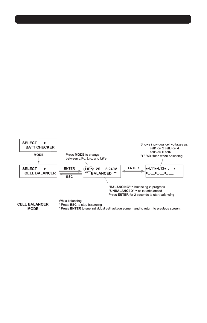
CELL BALANCER MODE
This mode indicates if cells in a LiPo pack are balanced, unbalanced,
or in the process of being balanced. Discharge-balancing can be
started in this mode, applying a 180mA maximum discharge current
to reduce the voltage of each cell to the voltage of the lowest cell in
the pack.
1. Connect the 2S-7S lithium battery to the balancing terminals on
the meter. Make sure the negative wire of the battery’s balancing
plug is connected to the terminal at far right as shown in Fig. 1 on
page 6. Do NOT connect the lithium battery’s main lead to the meter.
2. The BATT CHECKER screen should appear automatically. Press
MODE until the CELL BALANCER screen appears.
3. Press ENTER to view this function.
4. The top line of the display will show the lithium type, the number
of cells detected in the pack, and total pack voltage. Press MODE
to change the battery type to match the battery connected to the
meter.
5. The bottom line of the display will show BALANCED or
UNBALANCED, to indicate the condition of the cells in the pack. If
UNBALANCED shows, press and hold ENTER for two seconds to
start the balancing function to equalize the voltage of all cells in the
pack. The display will show BALANCING at this time.
8
Page 9

6. Press ENTER to view the voltages for all cells in the pack. A
fl ashing “■” symbol next to any cell voltage indicates that cell is
being balanced. Press ENTER to return to the previous screen.
Press ESC to manually stop the balancing function. Once balancing
is complete the meter will automatically move to power down mode
in 15 seconds. Press ENTER to revive the meter which will revert to
the previous screen.
If balancing is not in progress, pressing ESC will return to the CELL
BALANCER screen.
POWER CHECKER MODE
This mode is for measuring total load current, battery voltage, used
battery capacity, and electric power. This function can be used to
measure data between a battery and electronic speed control, charger
and a battery, or discharger and battery. PowerMatch can measure and
store average, minimum, and maximum values in this mode.
Note that heating may occur within PowerMatch when high
currents are passed through the meter continuously for more
than 2 minutes. This may cause the accuracy of the readings
on the display to decrease. It’s therefore not recommended to
allow continuous current of over 50A to pass through the meter
continuously for more than 2 minutes. Once a load current has
passed continuously through the meter for 3 minutes all data on
the LCD will automatically begin to fl ash. This simply notes that
meter accuracy may be reduced as a result of internal heating if
higher currents are being passed through the meter. The fl ashing
will stop when the battery is disconnected from the meter, or if the
function is stopped manually by pressing ESC.
MEASURING DATA FROM BATTERY TO ESC:
1. Connect the 2S-7S lithium
battery to the BATTERY input as
shown in Fig. 5. Do NOT connect
the lithium battery’s balancing
lead to the meter.
2. The POWER CHECKER
screen should appear automatically. If not, press MODE until
this screen appears.
9
Page 10
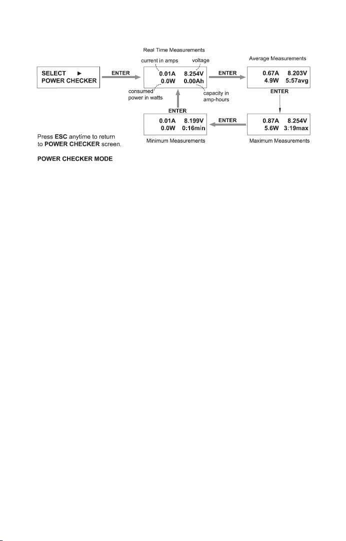
3. Press ENTER to view this function.
4. The fi rst screen shows the present condition of the battery and
meter. This includes current fl ow in amps (A), meter input voltage
(V), power across the meter in watts (W), and total energy that has
passed through the meter in amp-hours (Ah - not milli-amp hours).
Power can be delivered through the meter at this time (refer to
sections that follow). The meter will display and track current, power,
and energy data once 500mA has passed through for 3 seconds.
5. The meter can show three types of measured data: average,
maximum, and minimum values.
Average: Press ENTER to fi nd the “avg” screen, which shows
the average values measured. Measurements and data are
updated at continuous intervals.
Pressing MODE at any time will stop the counter and measured
data will be frozen at the last values recorded when the MODE
button was pressed. The time of this measurement is shown at
bottom right.
Pressing MODE again will reset all data on-screen back to zero,
and measurements will start again automatically once 500mA
has passed through the meter for 3 seconds.
Maximum: Press ENTER to see the “max” screen, which
shows the maximum values measured during the test which
is underway. Data is continuously monitored and updated only
when a higher value has been measured. The time when the
highest values are measured will be shown at bottom right.
10
Page 11

Pressing MODE will return to the “Average” screen. Pressing
MODE again will reset all data on-screen back to zero.
Minimum: Press ENTER to see the “min” screen, which
shows the minimum values measured during the test which is
underway. Data is continuously monitored and updated only
when a lower value has been measured. The time when the
lowest values are measured will be shown at bottom right.
Pressing the MODE button will return to the “Average” screen.
Pressing MODE again will reset all data on-screen back to zero.
MEASURING DATA DURING CHARGE OR DISCHARGE:
1. To charge: Connect the 2S-7S
lithium battery to the meter’s OUT
connection as shown in Fig. 6. Do
NOT connect the lithium battery’s
balancing lead to the meter. The
POWER CHECKER screen should
appear automatically. If not, press
MODE until this screen shows.
Connect the charger to the meter’s
BATTERY connection.
2. To discharge: Connect the battery to the meter’s BATTERY
connection and the discharger to the meter’s OUT connection.
3. Press ENTER to view this function.
4. Command the charger to start charge or discharge. Data should
appear on the meter’s LCD after 500mA of current has passed for 3
seconds.
WARNING!! Charging lithium-based rechargeable
batteries poses a risk of FIRE! NEVER leave lithium
batteries unattended while being charged! ALWAYS
charge lithium-based batteries in a fi reproof location!
Always follow the instructions provided with the
lithium battery and lithium charger when charging lithium batteries!
Lithium batteries should NEVER get warm or change shape
anytime during charge! Disconnect batteries IMMEDIATELY if they
become excessively warm or hot or change shape at any time, and
refer to the Troubleshooting Guide in the battery and/or charger’s
11
Page 12

instructions for details. Do not discharge LiPo or Li-Ion batteries to
a voltage that is too low. Failure to do so could result in the battery
failing when being re-charged and causing a FIRE! Always read
the instructions provided with lithium batteries and lithium chargers
prior to use!
USER SETTING MODE
This function allows the user to set the lowest cell voltage that the
meter will allow before giving a CELL VOLT LOW warning on-screen.
1. Connect the lithium battery to the BATTERY lead.
2. Press and hold the ESC button for three seconds. The SET LOW
VOLT screen will appear.
3. To change the battery type press ENTER. Each press of the
ENTER button will scroll the screen through LiPo, LiIo, or LiFe
battery types. It’s important to set this to the proper battery type so
the meter can select the appropriate adjustable voltage range for
the battery type.
4. To change the low voltage setting for the battery type, press
MODE. Each press of MODE will scroll the screen through the
possible low voltage setting options for each battery types in 0.1V
increments, as follows: LiPo: 2.9V - 3.6V LiIo: 3.0V - 3.6V LiFe:
2.5V - 3.2V
5. Pressing ESC will store the new settings and return to the
main screen.
12
Page 13
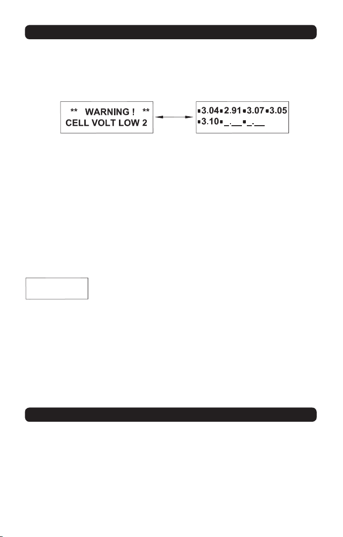
LOW BATTERY VOLTAGE and OUT OF BALANCE WARNINGS
If a lithium battery is connected to the meter’s balancing terminals
and a cell is determined to be at the minimum voltage as set in
the USER SETTING MODE, four tones will sound and a warning
screen like below will automatically show and alternate.
The cell with low voltage is shown on the bottom of the screen.
Pressing the ESC button will clear the warning and return the display
to the previous screen. Otherwise, after 15 seconds the meter will
sound two tones and enter sleep mode. Pressing ENTER will revive
the meter, returning it to the previous screen.
If the meter is accidentally set for the wrong battery type and the
warning appears, press ESC to clear the warning and return to the
previous screen. The meter will re-check the status of the battery for
5 seconds. During this time, press MODE to change the battery
type on the display.
CELL # OUT
OF BALANCE
If a lithium cell becomes +/-200mV out of balance
while in BATTERY CHECKER MODE or CELL
BALANCER MODE the warning message at left
will show. The “#” symbol denotes which cell is out of balance. If
this occurs, press ESC to manually stop the function in progress. If
the error occurred while in BATTERY CHECKER MODE, dischargebalance all cells in the pack to re-balance all cells (see the CELL
BALANCER MODE section on page 8). If the error occurred while in
CELL BALANCER MODE, the cell in question might have a problem
and no longer be suitable for use – contact your battery supplier for
further details.
ERROR INDICATIONS and SAFETY FEATURES
This meter uses solid-state circuitry to protect against potential
damage which could be caused by reverse polarity conditions. If
input power is connected backwards the screen might turn black
and no other operation will occur, but the meter will be protected
from damage. Re-check all input connections to make sure it is
connected properly.
13
Page 14

If connected in-line with a battery and charger, and the voltage
setting in the charger is too high for the battery that is connected,
a CELL VOLT LOW warning message will show. It may take up to
5 minutes for this error to show. Disconnect the battery from the
meter, and re-check all settings in the charger before proceeding.
TROUBLESHOOTING GUIDE
PROBLEM: Display does not work or turns black when connected
to a battery or other power source. Check the battery or power
source for proper power. Check input connections for proper contact,
making sure it’s not connected backwards. Meter is overheated.
Disconnect battery and allow meter to cool.
PROBLEM: Charger will not lock into charge mode when charging
through the meter. Or, the discharger will not lock into discharge
mode when discharging through the meter. Make sure the POWER
CHECKER function is active with the “Real Time Measurements”
screen showing – see page 10.
PROBLEM: CELL VOLTS LOW warning shows but battery/cell
voltages are acceptable. Make sure the meter is set for the proper
battery type according to the battery connected to the meter. Make
sure the low battery voltage setting isn’t too low – see page 13.
PROBLEM: LCD and/ or controls do not function properly. Input
power might be connected backwards, and require re-connection.
Contact Hobby Services for further details.
1-YEAR LIMITED WARRANTY – *U.S.A. and CANADA ONLY
Great Planes warrants this product to be free from defects in
materials and workmanship for a period of one (1) years from the
date of purchase. During that period, Great Planes will, at its option,
repair or replace without service charge any product deemed
defective due to those causes. You will be required to provide
proof of purchase (invoice or receipt). This warranty does not cover
damage caused by abuse, misuse, alteration or accident. If there
is damage stemming from these causes within the stated warranty
period, Great Planes will, at its option, repair or replace it for a
service charge not greater than 50% of its then current retail list
price. Be sure to include your daytime telephone number in case
14
Page 15

we need to contact you about your repair. This warranty gives you
specifi c rights. You may also have other rights, which vary from state
to state.
For service on your Great Planes product, warranty or non-warranty,
send it post-paid and insured to:
Hobby Services Tel: 217-398-0007
3002 N. Apollo Drive, Suite #1
Champaign, Illinois 61822
hobbyservices@hobbico.com
*For warranty and service information if purchased outside the
USA or Canada, see the additional warranty information insert (if
applicable) or ask your retailer for more information.
www.greatplanes.com www.electrifl y.com
Made in China
15
Page 16

™
GPMM3220 v2
 Loading...