

Page 1

ElectriFly’s™BL-8 Brushless ESC is designed for powering small, brushless motors for 3D aerobats and flat-foam airplanes. The
BL-8 ESC is capable of delivering 8 amps of current continuously, or 9 amps of surge current, and has numerous programmable
features including battery type (NiCd/NiMH or Li-Po), soft-start, brake, timing and more.
INSTRUCTIONS
Input Voltage: 5 – 10 NiCd/NiMH cells, 2-3 Li-Po cells
(20V input w/o BEC)
Output current: 8A continuous max., 9A surge max.
BEC: 5V / 1.5A
Operating frequency: 8 or 16kHz programmable
On resistance: 0.013 ohms
Brake: on / off
Acceleration: soft, hard or automatic
Low voltage cutoff: programmable
Max. temp.cutoff: 230°F [110°C]
Dimensions: 0.87 x 0.16 x 0.83" [22 x 4 x 21mm]
Weight: 0.42oz. with wires [12g]
• Great for small, high-performance airplanes, from flat foams to
built-up 3D’s.
• Fully proportional forward with brake.
• Very smooth throttle response.
• Custom BEC circuit handles up to 1.5A – great for models
requiring up to three high-powered servos.
• Li-Po compatible, as well as NiCd and NiMH batteries.
• Other programmable features include:
• Brake Control: On/off.
• Safe-Start: On/off, prevents accidental motor spin at start-up.
• Switching frequency: 8kHz or 16kHz, to optimize battery runtime and cool operation.
• Low-V oltage Control:Reduce or cut motor power, but maintain
radio control.
• Timing: Soft (7 degrees), hard (30 degrees for outrunners),
or automatic.
• Reverse rotation.
• Includes over-temperature protection.
• Pre-installed universal radio connector, micro batter y connector,
and 2mm female bullet motor connectors.
Please read and follow these instructions carefully before using.
• Do NOT apply an input voltage that exceeds the maximum
specification above.
• Do NOT apply currents to the motor that exceeds the maximum
specifications above.
• Do NOT allow the input or output connectors to accidentally touch
each other while power is applied. Make sure all connections are
insulated electrically.
• Do NOT allow water or moisture to make contact with the ESC’s
circuitry as it can cause permanent damage.
• Do NOT place the ESC in a location inside the airplane where air
cannot flow. Always provide a path for external air to flow freely
across the ESC while in operation.
• Do NOT attempt to touch a rotating motor as personal injury can
result! If setting up the motor/ESC on the workbench, make sure
the motor is securely attached and that nothing is connected to the
output shaft BEFORE applying power.
• Always connect the power battery just before flight, and disconnect
the battery immediately after the flight has ended.
The BL-8 ESC is designed to work with brushless motors of all types –
except motors that include sensors. Its adjustable timing makes the
BL-8 a great choice for great operation with inner-rotating and outrunner
type brushless motors. Do NOT attempt to use the BL-8 ESC with
traditional brushed motors as permanent damage may result!
IMPORTANT!! The ESC should always be mounted in a location
which allows good airflow for proper cooling!! Failure to allow
good airflow over the ESC during operation can cause severe
overheating, resulting in thermal shutdown and/or permanent
damage to the ESC!
Determine the best location for the ESC on the fuselage. If the
location of the ESC is not vented or ducted to allow airflow inside and
out of the fuselage you will need to create one or more vents or ducts.
For some airplanes, mounting the ESC in front of the firewall or next
to the motor might be good options.Other airplanes only allow for the
ESC to be mounted behind the firewall, in which case air vent holes
will need to be cut in the firewall, and air exit holes may need to be
cut in the tail end of the fuselage.
Mount the ESC to the airplane in a way that minimizes the amount of
shock and vibration to the ESC.Attaching the body of the ESC to the
model with double-sided foam tape or Velcro
®
is recommended. It’s
also a good idea to try and locate the body of the ESC as far away
from the electric motor as possible, to help avoid any unwanted
electrical interference.
This ESC has a built-in “BEC” or “Battery Eliminator Circuit” which
takes power from the airplane’s main pow er battery and supplies it to
the receiver and servos. The BEC delivers this power through the
receiver connector. Therefore, it is not necessary to connect a
separate battery to the receiver. Always connect the ESC’s receiver
connector to the receiver’s throttle channel (see your radio’s
instruction manual for details). IMPORTANT!! The BL-8’s BEC
circuit is rated to handle up to 1.5A of current for short bursts –
NOT continuous 1.5 amps of current.If your application will use
higher powered servos it is very important to make sure to
mount the ESC so that a large amount of air can flow over the
ESC during operation.
The BL-8’s
receiver
connector is a
universal style
plug, and will
connect
directly to
most R/C
receivers
without need
for physical
modification or re-wiring.The orange “signal” wire on the ESC’s receiver
plug should be in the same position in the receiver slot as the white wire
STEP 2 – THE BEC CIRCUIT & RECEIVER CONNECTION
STEP 1 – MOUNTING THE SPEED CONTROL
COMPATIBLE MOTORS
IMPORTANT PRECAUTIONS
SPECIAL FEATURES
SPECIFICATIONS
™
Page 2
2
on Futaba®, the blue wire on the newer Airtronics “Z” connector, the
yellow wire on the Hitec “S” connector, or the orange wire on the JR
connector. WARNING: This connector is NOT directly compatible with
the old Airtronics connector style. Use an Air tronics Servo Adapter to
connect this ESC to the older style Airtronics radios.
DISABLING THE BEC CIRCUIT
If using more than 10 NiCd/NiMH or 3 Li-Po cells, it will be necessary
to disable the speed control’s BEC circuit and connect a separate
battery to power the receiver and servos. Failure to do so will
permanently damage the BEC circuit. To disable the BEC circuit:
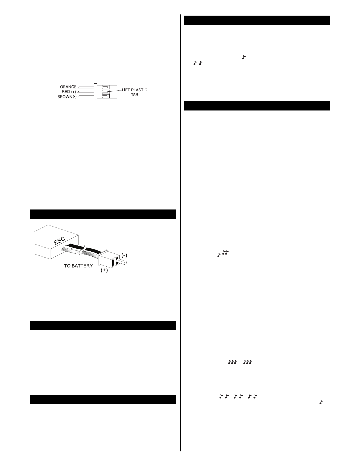
A. The red wire and its terminal should be removed from the plastic
shell. To do this use a small flat bladed screwdriver to slightly,
carefully raise the plastic tab holding the metal pin. Carefully pull
the red wire out of the receiver plug.Or, cut a small section of the
red wire out completely with wire cutters.
B. Always make sure to cov er the bare terminal or cut wire with electrical
tape or shrink tubing to avoid an unwanted short circuit condition.
C. Connect the ESC’s receiver connector to the receiver’s throttle
channel (see your radio’s instruction manual for details).
A separate battery will then need to be connected to the receiver.
When the BEC circuit is disabled, it will be important to remember not
to exceed the ESC’s maximum rated current!
WARNING: NEVER ALLOW THE BARE RED (+) AND BLACK (-)
WIRES TO TOUCH ON ANY RECEIVER OR ESC, AS
PERMANENT DAMAGE WILL RESULT TO BOTH ITEMS AND
VOID ALL WARRANTIES!
A polarized micro
connector is preinstalled for
connecting the ESC
to an external
battery pack. It’s a
good idea for the
length of wire
between the battery
and ESC to be no
longer than 6
inches. IMPORTANT! Make sure the polarity of the battery’s
wires/connector matches the polarity of the wires/connector on
the ESC, with the battery and ESC’s red (+) wires connected and
the black (-) wires connected together.NEVER allow the bare red
(+) and black (-) wires to touch as permanent damage will result
to both items and void all warranties.
The BL-8 has three output leads. Female 2mm bullet connectors are
pre-installed on each lead. These connections are not polarized, so
there is no need to match the color of the ESC’s wires to the motor’s
wires. Once connected to the motor, make sure all connections are
insulated electrically .Failure to do so could result in permanent damage
to the motor/ESC if the output leads touch each other while power is
applied to the ESC, thus voiding all warranties. If the motor operates in
the opposite direction desired, switch any two of the motor wires to
reverse the motor’ s rotation, or adjust the “re verse rotation”setting in the
BL-8’s programming (see page 3).
Proper adjustment of the transmitter’s controls is critical for proper
operation of the ESC.The transmitter’s throttle channel adjustments
should be set as follows:
A. Set the throttle travel adjustment (ATV, EPA or ATL) to maximum
(+/- 100% or the greatest value available).
B. Set the throttle trim and sub-trim to neutral, or zero.
C. For most radio types (including Futaba, Hitec and others) set the
throttle channel’s reversing option to “reverse.”
The BL-8’s normal start-up procedure is very simple, as follows:
A. Turn the transmitter’s power switch to “ON.”
B. Move the Tx throttle stick to MINIMUM position.
C. Connect the battery to the ESC.
D. You will hear one tone
“”if the brake is set to “ON,”or two tones
“”to indicate the brake is set to “OFF.”
E. If the brake setting is O.K.and no other programming adjustments
are needed, skip directly to Step 8 and get ready to fly. If you do
wish to change the brake setting or any other programmable
feature, disconnect the battery and go to Step 7 below.
The BL-8 has seven programmable features, and will automatically
step through each feature in order as shown below. It is not
necessary to wait for the ESC to step through all seven
programmable features unless you wish to change the setting of the
last feature. Each programmable feature has its own distinguishing
series of audible tones. Selecting/changing features is accomplished
by moving the Tx’s throttle stick in conjunction with certain tones that
are emitted by the ESC. Anytime a programmable feature has been
set the ESC will memorize the setting until it’s changed again
manually. Before entering the programming mode, remove the
propeller from the motor and make sure the battery is disconnected
from the ESC. It’s a good idea to read through all steps below
BEFORE attempting to program your ESC.
IMPORTANT!! It’s critical to remember that only ONE
programmable feature can be adjusted at a time. To change more
than one programmable feature, after changing the first feature you
must disconnect the battery from the ESC, reconnect the battery,
then re-start the programming mode below to change the next
programmable feature. It will be necessary to repeat this process for
each programming change that you wish to make.
A. Turn the transmitter’s power switch to “ON.”
B. Move the Tx’s throttle stick to FULL throttle.
C. Connect the battery to the ESC.After a 5 second delay two tones
will sound “ ” to indicate the programming mode has been
entered. The ESC will automatically begin scrolling through all of
the programmable features in this order: brake > battery type >
reverse rotation > soft start > low voltage indication > timing >
switching frequency > restore defaults > RPM control.Follow the
points below to change any of these features.
D. BRAKE: T o change the brak e setting, simply pull the throttle stic k
to minimum within five seconds of hearing the programming tones
noted in step C above. This will change the state of the brake
setting - if the brake was on this will turn it off, and vice-versa. You
can determine which setting is active by listening to the arming
tone. One tone indicates that the brake is enabled, and two tones
indicates that the brake is disabled. Skip to Step 8 if you do not
wish to make any other programming changes. To CHANGE
ANOTHER programmable feature disconnect the battery from the
ESC and return to Step B above.
E. BATTERY TYPE: The ESC will automatically sound three
different series of tones to indicate the three battery type settings
as shown below. If you do NOT wish to change the battery setting
wait after the “ ” tones sound and the ESC will
automatically skip to the reverse rotation feature below. To
CHANGE the battery type, move the throttle stick to minimum
when you hear the tones that match the setting you wish to have.
For example, to set for a “2-cell Li-Po” battery wait until the tones
for NiCd batteries have ended, then when 2 short tones sound
repeatedly “
” move the Tx throttle stick to
minimum position.The ESC will then sound a single tone
“”to
indicate the new setting was accepted, and the ESC is now armed
and ready for operation.Skip to Step 8 if you do not wish to make
any other programming changes. To CHANGE ANOTHER
programmable feature disconnect the battery from the ESC and
return to Step B above.
WARNING: Failure to set the proper
battery type will likely result in unwanted operation and/or
damage to your battery.
STEP 7 – PROGRAMMING MODE
STEP 6 – NORMAL START UP
STEP 5 – TRANSMITTER ADJUSTMENTS
STEP 4 – MOTOR CONNECTIONS
STEP 3 – BATTERY CONNECTION
Page 3

3
Battery type Series of tones
NiCd: (cuts at 50% of initial battery voltage)
2-cell Li-Po: (cuts at 5.6V)
3-cell Li-Po: (cuts at 8.4V, factory default)
F. REVERSE ROTATION: The ESC will sound a ser ies of tones
as shown below to indicate the direction of motor rotation can
be reversed. If you do NOT wish to change the direction of
rotation wait 5 seconds after these tones sound and skip to the
soft-start feature below. To CHANGE the direction of motor
rotation, move the throttle stick to minimum when you hear
these tones. The ESC will sound “ ” to indicate the new
setting was accepted, and the ESC is now armed and ready
for operation. Skip to Step 8 if you do not wish to make any
other programming changes. To CHANGE ANOTHER
programmable feature disconnect the battery from the ESC
and return to Step B above.
Note: It may be necessary to
reverse a motor’s rotation when using a gear drive.
Reverse Rotation:
G. SOFT-START: The ESC will sound two different series of
tones to indicate the two soft-start settings as shown below.If
you do NOT wish to change the soft-start setting wait 5
seconds after the “ ” tones sound and skip to the low
voltage indication feature below. To CHANGE the soft-start
setting, move the throttle stick to minimum when you hear the
tones which match the setting you wish to have. The ESC will
sound “ ” to indicate the new setting was accepted, and the
ESC is now armed and ready for operation. Skip to Step 8 if
you do not wish to make any other programming changes. To
CHANGE ANOTHER programmable feature disconnect the
battery from the ESC and return to Step B above.
Note: It’s
often recommended to enable the soft-start feature when
using the motor with a gear drive, to help prevent breakage of
the gears as the motor begins rotation (especially when a
large diameter prop is being used). Enabling the soft-start
feature is optional when not using a gear drive, but can be
used as a safety precaution.
Enable: (factory default)
Disable:
H. LOW VOLTAGE INDICATION: The ESC will sound three
different series of tones to indicate the three low voltage
indication settings as shown below. If you do NOT wish to
change the low voltage indicator setting wait 5 seconds after
the “ ” tones sound and skip to the timing feature below.
To CHANGE the low voltage indicator setting, move the
throttle stick to minimum when you hear the tones that match
the setting you wish to have. The ESC will sound “ ” to
indicate the new setting was accepted, and the ESC is now
armed and ready for operation. Skip to Step 8 if you do not
wish to make any other programming changes.To CHANGE
ANOTHER programmable feature disconnect the battery from
the ESC and return to Step B above.
This feature warns you that the battery’s voltage has dropped
to a dangerously low level. The ESC can be set to give a
warning by either reducing or totally cutting throttle.When the
throttle change is observed the airplane should be landed
quickly. This feature can also be set to “ignore” so that no
indication is given.When the low voltage indication is given the
ESC will still deliver power to the receiver and servos to
control the airplane, and regular throttle control can be
regained by cycling the throttle stick to full minimum and back
upward, but the airplane should be landed quickly before
all control is lost. The voltages at which the low voltage
indications will activate are as shown in the
“BA TTERY TYPE”
section above.
Ignore (no indication):
Reduce throttle power (factory default):
Cut motor power:
I. TIMING (rotor advancement timing): The ESC will sound
three different series of tones to indicate the three timing
advancement options as shown below. If you do NOT wish to
change the timing setting wait 5 seconds after the tones “ ”
sound and skip to the switching frequency setting below. To
CHANGE the timing setting, move the throttle stick to
minimum when you hear the tones that match the setting you
wish to have. The ESC will sound “ ” to indicate the new
setting was accepted, and the ESC is now armed and ready
for operation. Skip to Step 8 if you do not wish to make any
other programming changes. To CHANGE ANOTHER
programmable feature disconnect the battery from the ESC
and return to Step B above.
Selecting the proper timing will help to optimize the overall
efficiency of your power system. The “automatic” setting is
acceptable for all types of brushless motors.The “soft” setting
is for “multi-pole” or “inner-rotating” motors. The “hard” setting
is for outrunner type motors.
Automatic (7-30 degree advance,factory default):
Soft (7 degrees):
Hard (30 degrees):
:
J. SWITCHING FREQUENCY: The ESC will sound two different
series of tones to indicate the two switching frequency options as
shown below. If you do NOT wish to change the switching
frequency wait 5 seconds after the tones “ ” sound and skip
ahead to the restore factory default setting below. To CHANGE
the switching frequency, move the throttle stick to minimum when
you hear the tones that match the setting you wish to have. The
ESC will sound “ ” to indicate the new setting was accepted,
and the ESC is now armed and ready for operation.Skip to Step
8 if you do not wish to make any other programming changes.To
CHANGE ANOTHER programmable feature disconnect the
battery from the ESC and return to Step B above.
Note: The
8kHz frequency is good for all types of 2-pole and outrunner type
motors, and the 16kHz setting is good for “multi-pole” or “innerrotating” motors.
8kHz (factory default):
16kHz:
K. RESTORE FACTORY DEFAULT SETTINGS: The ESC will
sound a series of tones to indicate the function for restoring all
ESC settings back to the factory defaults.If you do NOT wish
to restore all settings back to factory defaults wait 5 seconds
after these tones stop and skip ahead to the active RPM
control setting below. To CHANGE all settings back to the
factory defaults, move the throttle stick to minimum when you
hear these tones. The ESC will sound a single tone “ ” to
indicate the new setting was accepted, and the ESC is now
Page 4

armed and ready for operation. Skip to Step 8 if you do not
wish to make any other programming changes.To CHANGE
ANOTHER programmable feature disconnect the battery from
the ESC and return to Step B above.
L. ACTIVE RPM CONTROL: The ESC will sound four different
series of tones to indicate the four RPM control options as
shown below. To CHANGE the RPM control setting, move the
throttle stick to minimum when you hear the tones that match
the setting you wish to have .The ESC will sound a single tone
“ ” to indicate the new setting was accepted. The ESC will
now be armed and ready for operation, and skip to Step 8. If
you do NOT wish to change the RPM setting do not move the
throttle stick, and after the last tones sound the ESC will sound
“ ” to indicate the programming mode has finished, the ESC
is now armed, and go to Step 8.
The active RPM control function is designed for use with small
electric helicopters. Selecting the proper RPM maximum
control value will help to prevent the ESC from overpowering
the model during flight. Refer to your helicopter’s instruction
manual for a recommended maximum RPM value. Leave this
setting “OFF” for model airplanes.
RPM control off (factory default):
first range (20,000 RPM max.):
second range (50,000 RPM max.):
third range (100,000 RPM max.):
Once all connections have been made and all programming has
been set it’s a good idea to perfor m a range test with your radio
before attempting a flight to ensure that a good Rf link exists
between the transmitter and the airplane. With the Tx antenna
collapsed and a helper holding the airplane, apply full throttle and
operate the other flight controls while walking away from the
airplane. Full control should be maintained at a range of up to
approximately 75 to 100 feet a wa y from the airplane.If the system
fails this range test it may be necessary to re-route the location of
the Rx and/or its antenna away from linkages or electronic
components in the airplane. Refer to the radio’s instruction
manual for further details.
ESC DOES NOT WORK
Problem: Motor and/or Rx or servos do not function.
1. Batter ies are dead. Recharge batteries.
2. Check for incorrect or faulty battery connections.
3. Check for a damaged connection between ESC and Rx.
4. Check for faulty motor connections.
5. Internal damage. Unit may require service. See
“Service
Procedures.”
6. Make sure the ON/OFF switch is set to “ON.”
Problem: Motor rotates in the wrong direction.
1. Motor wires attached incorrectly. See
“Step 4 – Motor
Connection.”
2. “Reverse rotation” setting in ESC must be changed. See
“Step 5 – Speed Control Setup.”
ESC WORKS BUT OTHER PROBLEMS EXIST
Problem: Rx glitches or stutters dur ing acceleration.
1. Rx mounted too close to ESC causing interference. Relocate
Rx away from ESC.
2. Check for faulty power connections.
Problem: Rx and servos function, but programming tones do not
function properly (does not emit setup tones).
1. ESC may need to be reset.Remove and re-apply power to the ESC.
2. Check the Tx throttle channel to see if it needs to be reversed.
3. Check ATV, EPA or ATL must be set to maximum or +/- 100%.
Problem: Model runs slowly or has no acceleration.
1. The ESC is not set up properly. Repeat
“Step 5 – Speed
Control Setup.”
2. Check for faulty battery and/or motor connections.
3. Tx is improperly adjusted. Repeat
“Step 4 – Transmitter
Adjustments.”
Problem: Rx and servos function, but motor does not rotate.
1. Tx is improperly adjusted. Repeat
“Step 4 – Transmitter
Adjustments.”
2. Check for faulty motor connections.
3. Motor is bad or hung up. Clean or replace motor.
Problem: Motor seems to function very inefficiently, has difficulty
in starting to rotate, or hesitates when trying to rotate.
1. The timing feature is set improperly for the selected motor.See
“Step 5 – Speed Control Setup.”
2. Check for faulty motor connection.
3. Problem with motor.Tr y a different motor.
Problem: Low voltage cutoff indicator activates at improper voltage.
1. Low voltage cutoff feature set improperly. See
“Step 5 –
Speed Control Setup.”
2. Bad cell or battery pack. Replace batter y.
ESCs that operate normally when received will be charged a
minimum service fee and return shipping charges.Before sending
your ESC in for service, it is important that you review the
“T roubleshooting Guide”
in this instruction sheet.The ESC may
appear to have failed when other problems exist in the system,
such as a defective Tx, Rx or servo, or incorrect
adjustments/installation.
• Hobby dealers are not authorized to replace ESCs thought to
be defective.
• Do not cut the input harness, switch harness, or power wires
of the ESC before sending it for service.A fee will be charged
for cut wires which must be replaced for testing.
Great Planes®warrants this product to be free from defects in materials and
workmanship for a period of 180 days from the date of purchase. During that
period, Great Planes will, at its option, repair or replace without service charge
any product deemed defective due to those causes. You will be required to
provide proof of purchase (invoice or receipt). This warranty does not cover
damage caused by abuse, misuse, alteration or accident. If there is damage
stemming from these causes within the stated warranty period, Great Planes
will, at its option, repair or replace it for a service charge not greater than 50%
of its then current retail list price. Be sure to include your daytime telephone
number in case we need to contact you about your repair. This warranty gives
you specific rights.You ma y also hav e other rights, which vary from state to state.
For service on your Great Planes product, warranty or non-warranty, send it
post-paid and insured to:
HOBBY SERVICES
3002 N. Apollo Drive, Suite 1
Champaign, IL 61822
(217) 398-0007
e-mail:
hobbyservices@hobbico.com
*For warranty and service information if purchased outside the USA or Canada,
see the additional warranty information insert (if applicable) or ask your retailer
for more information.
www.greatplanes.com
www.electrifly.com
180 DAY LIMITED WARRANTY – *U.S.A.AND CANADA ONLY
SERVICE PROCEDURES
TROUBLESHOOTING GUIDE
STEP 8 – RANGE TEST
GPMZ0307 for GPMM2070Made in China Entire Contents © Copyright 2005
 Loading...