

Great Planes GPMM2055 User Manual
™
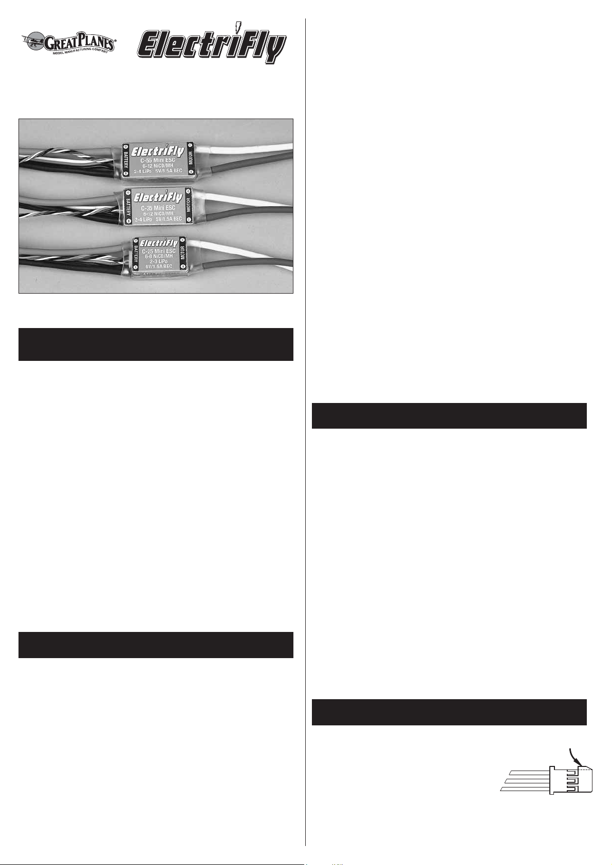
C-25, C-35 and C-55 High-Power High-Frequency
Electronic Speed Controls w/BEC
INTRODUCING THE ELECTRIFLY LINE OF
HIGH-POWER BRUSHED ESC’s
The ElectriFly™ line of High-Power ESC’s feature the
“Safe Start” system to prevent accidental motor starts by
disabling the motor circuitry until the throttle stick is
moved to full throttle, then to the “off” position.
Other features include BEC (Battery Elimination Circuitry)
which allows the motor battery to power the receiver and
servos. When the motor battery voltage is reduced to a
set voltage per cell, the low-voltage cut-off circuitry stops
the motor while continuing to supply power to the
receiver and servos. This eliminates the need for and
weight of a separate receiver battery. The ElectriFly line
of ESC’s comes with thermal protection that reduces the
throttle to 70% when the maximum temperature is
reached. These ESC’s can easily be adjusted for use
with NiCd/NiMH or Li-Po batteries. These ESC’s function
with brushed motors only!
SPECIFICATIONS
C-25
Dimensions: 0.98" x 0.43" x 0.71"
[25 x 11 x 18mm]
Weight: 0.85oz. [24g]
Input Voltage: 6-10 cells NiCd/NiMH
2-3 cells Li-Po
Continuous Current: 25 amps
Max Rated Current: 35 amps
BEC Voltage: 5V / 1.5A
Low-Voltage Cutoff: 0.8 volts per cell NiCd/NiMH
2.75 volts per cell Li-Po
Battery Plug: Star
®
Plug
Switching Frequency: 1.3 kHz
C-35
Dimensions: 1.30" x 0.43" x 0.71"
[33 x 11 x 18mm]
Weight: 1.08oz. [31g]
Input Voltage: 6-12 cells NiCd/NiMH
2-4 cells Li-Po
Continuous Current: 35 amps
Max Rated Current: 45 amps
BEC Voltage: 5V / 1.5A
Low-Voltage Cutoff: 0.8 volts per cell NiCd/NiMH
2.75 volts per cell Li-Po
Battery Plug: Star
®
Plug
Switching Frequency: 1.3 kHz
C-55
Dimensions: 1.42" x 0.43" x 0.71"
[33 x 11 x 18mm]
Weight: 1.22oz. [35g]
Input Voltage: 6-12 cells NiCd/NiMH
2-4 cells Li-Po
Continuous Current: 50 amps
Max Rated Current: 65 amps
BEC Voltage: 5V / 1.5A
Low-Voltage Cutoff: 0.8 volts per cell NiCd/NiMH
2.75 volts per cell Li-Po
Battery Plug: Star
®
Plug
Switching Frequency: 1.3 kHz
IMPORTANT PRECAUTIONS
Read and follow these instructions carefully before
using.
• Do not operate the airplane on or near water. Never
allow water, moisture or any foreign material onto the
ESC’s PC board.
• Never use more cells then specified for the main
battery pack.
• The ceramic capacitors must be properly installed on
the motor to prevent radio interference.
• Always disconnect the motor battery from the ESC
when not in use.
• Always switch on the transmitter before switching on
the ESC.
• Use heat-shrink tubing to insulate any bare wires from
the motor battery to the ESC and from the ESC to the
motor to prevent a short circuit.
• Allow the ESC to cool before touching.
STEP 1 THE RECEIVER PLUG
The receiver plug attached to the
TRIM OFF
speed control plugs directly into a
Futaba
®
“J” receiver. However, if you
are using an Airtronics “Z,” Hitec “S” or
JR receiver, you will need to slightly
modify the receiver plug on the ESC. To modify the plug,
use a hobby knife or wire cutter to carefully cut off the
alignment tab on the side of the receiver plug as shown.

The white “signal wire” on the ESC receiver plug should be
in the same position in the receiver slot as the white wire
on Futaba, the blue wire on the new Airtronics “Z”
connector, the yellow wire on the Hitec “S” connector or the
orange wire on the JR connector. WARNING: This
connector is NOT directly compatible with the old Airtronics
connector style. Use an Airtronics Servo Adapter to
connect this ESC to the older style Airtronics radios.
NEVER ALLOW THE BARE RED (+) AND BLACK (-)
WIRES TO TOUCH ON ANY RECEIVER OR ESC, AS
PERMANENT DAMAGE WILL RESULT TO BOTH
ITEMS AND VOID ALL WARRANTIES.
STEP 2 MOUNTING THE SPEED CONTROL
Determine the best location for the ESC inside the
fuselage. The ESC should be in a position which allows
good airflow for proper cooling, and close enough so the
wires reach the motor. It is highly recommended to put
cooling air intake holes in the front of the fuselage and
exit holes towards the aft end.
IMPORTANT: When using the ESC’s with the maximum
number of cells and at the maximum current draw, the
ESC must have good air flow over it to keep it cool.
The best method to mount the ESC in the fuselage is
with Velcro
saturate the wood with thin CA and
1/4" x 1"
®
. If the ESC will be mounted on wood, first
allow to dry. Cut a
piece of Velcro (both hook and loop)
. Attach the
hook (hard) material to the inside of the fuselage. Clean
the side of the ESC with rubbing alcohol and attach the
loop (soft) material. The ESC on/off button should be
positioned in the battery compartment. Do not apply
Velcro to the top or bottom of the ESC’s. These are the
locations of the heat sinks and must not be covered.
• Solder the remaining leads from both capacitors to the
side of the motor
case.
• Cut two pieces of heat-shrink tubing long enough to
cover both leads on the .047µF capacitor, leaving
approximately 1/4" of the lead exposed at the bottom.
• Solder one of the leads to the positive brush terminal
and the other lead to the negative brush terminal.
• Solder the positive (+) lead from the ESC to the
positive brush terminal on the motor and the negative
(-) lead to the negative brush terminal on the motor.
.10μF CAPACITOR (104)
SOLDER TO SIDE
OF MOTOR
NEGATIVE (–)
BRUSH TERMINAL
POSITIVE (+)
BRUSH TERMINAL
F CAPACITOR (473)
.047μ
STEP 4 TRANSMITTER ADJUSTMENTS
Adjusting the transmitter is critical for proper ESC
operation. The transmitter throttle adjustments should be
set as follows:
1. Set the travel adjustment, ATV, EPA or ATL to 100%.
2. Set the throttle trim and sub trim to neutral or zero.
3. Set the throttle reversing switch to reverse on Futaba
transmitters and to normal on most other transmitters.
STEP 5 SPEED CONTROL SETUP
Before you begin this setup, remove the propeller from
the motor. Then plug the ESC into the throttle channel on
the receiver and adjust the transmitter.
STEP 3 INSTALL THE MOTOR CAPACITORS
Motors generate radio noise which can interfere with
your receiver and cause problems. Your ESC includes
two .10µF (104) and one .047µF (473) non-polarized,
ceramic capacitors. These capacitors must be used at all
times, and on every motor to help reduce the radio noise
generated by the motor and prevent possible damage to
the ESC.
• Cut a piece of heat-shrink tubing long enough to cover
one of the leads on both of the .10µF capacitors,
leaving approximately 1/4" of the lead exposed at
the bottom.
• Solder the 1/4" of exposed lead from one of the
capacitors to the positive brush terminal on the motor
end cap.
• Solder the 1/4" of exposed lead from the second
capacitor to the negative brush terminal on the motor
end cap.
BATTERY SETUP MODE
1. Switch on the transmitter. With the ESC off, press and
hold the on/off button for 4-5 seconds until the red
LED goes off. Then, release the button.
2. Pressing the button again will cause the blue light to
stay on or start flashing. To change settings, press the
button until the correct setting is obtained.
NiCd/NiMH: The blue light will be on.
2-cell Li-Po: The blue light will blink 2 times.
3-cell Li-Po: The blue light will blink 3 times.
4-cell Li-Po: The blue light will blink 4 times.
3. Once the battery type is set, press and hold the button
for 2-3 seconds until the red light comes on.
BRAKE SETUP
1. The factory brake default setting is “brake on.” To turn
the brake off, switch the transmitter on and set the
throttle stick to the brake position. Press the on/off
button on the ESC. The red and blue light should be on
or flashing for Li-Po and the motor should beep
3 times.
2
 Loading...