

Page 1
MICRO HIGH POWER
ELECTRONIC SPEED CONTROLS W/BEC
The ElectriFly C-7 Nano and C-12 Micro ESC’s feature the “Safe Start”
system to prevent accidental motor starts by disabling the motor circuitry
until the throttle stick is moved to full throttle, then to the “off” position.
Other features include BEC circuitry which allows the motor battery to
power the receiver and servos. When the motor battery voltage is
reduced to .7 volts per cell on NiCd/NiMH and 2.8 volts per cell on LiPo,
the low voltage cut-off circuitry stops the motor while continuing to supply
power to the receiver and servos.This eliminates the need for and weight
of a separate receiver battery. Both ESC’s are programmable for use
with NiCd/NiMH or LiPo batteries. These ESC’s function with brushed
motors ONLY.
C-7 Nano C-12 Micro
Dimensions: 0.66" x 0.28" x 0.43" 0.83" x 0.31" x 0.43"
[17 x 7 x 11mm] [21 x 8 x 11mm]
Weight: 0.20 oz [5.5g] 0.28oz [8g]
Input V oltage: 6-8 cell NiCd/NiMH 6-8 cell NiCd/NiMH
2-3 cell LiPo 2-3 cell LiPo
Max Rated Current: 7 Amps 12 Amps
BEC V oltage: 5V/1 Amp 5V/1 Amp
Low V oltage Cutoff: 0.80V/cell NiCd/NiMH 0.80V/cell NiCd/NiMH
2.75V per cell LiPo 2.75V per cell LiPo
Connectors: Micro Plug Micro Plug
Switching Frequency: 2.5 kHz 2.5 kHz
Servos: 3 Micro Servos 3 Micro Servos or
4 Micro with good cooling
Read and follow these instructions carefully before using.
• Do not operate the airplane on or near water. Never allow water,
moisture or any foreign material onto the ESC’s PC board.
• Never use more cells then specified for the main battery pack.
• The ceramic capacitors must be properly installed on the motor to
prevent radio interference.
• Always disconnect the motor battery from the ESC when not in use.
• Always switch on the transmitter before switching on the ESC.
• Use heat shrink tubing to insulate any bare wires from the motor battery
to the ESC and from the ESC to the motor to prevent a short circuit.
• Allow the ESC to cool before touching.
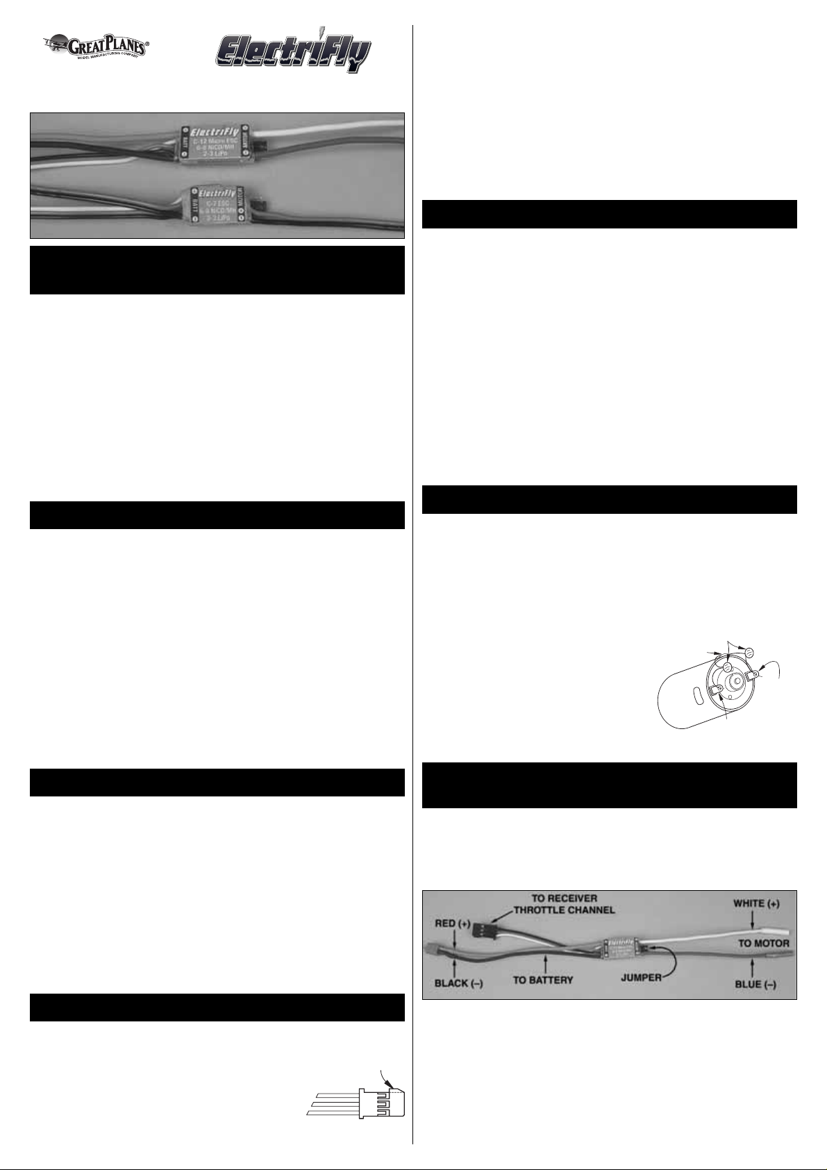
The receiver plug attached to the speed control
plugs directly into a Futaba “J” receiver.However, if
you are using an Airtronics “Z”, Hitec “S” or JR
receiver , you will need to slightly modify the receiver
plug on the ESC.To modify the plug, use a hobby
knife or wire cutter to carefully cut off the alignment
tab on the side of the receiver plug as shown.
The white “signal wire” on the ESC receiver plug should be in the
same position in the receiver slot as the white wire on Futaba, the
blue wire on the new Airtronics “Z” connector, the yellow wire on the
Hitec “S” connector or the orange wire on the JR connector.
WARNING: This connector is NOT directly compatible with the old
Airtronics connector style.Use an Airtronics Servo Adapter to connect
this ESC to the older style Airtronics radios.
NEVER ALLOW THE BARE RED (+) AND BLACK (–) WIRES TO
TOUCH ON ANY RECEIVER OR ESC, AS PERMANENT DAMAGE
WILL RESULT TO BOTH ITEMS AND VOID ALL WARRANTIES.
Determine the best location for the ESC inside the fuselage.The ESC
should be in a position which allows good airflow for proper cooling,
and close enough to the motor so the motor wires reach the motor.It
is highly recommended to put cooling air intake holes in the front of
the fuselage and exit holes towards the aft end.
IMPORTANT: When using the ESC’s with the maximum number of
cells and servos, and at the maximum current draw, the ESC must
have good air flow over it to keep it cool.
The best method to mount the ESC in the fuselage is with Velcro
®
.If
the ESC will be mounted on wood, first saturate the wood with thin CA
and allow to dry. Cut a piece of Velcro (both hook and loop)
approximately 1/2" x 1". Attach the hook (hard) mater ial to the inside
of the fuselage.Clean the bottom of the ESC (the side with the wires)
with rubbing alcohol and attach the loop (soft) material.
Motors generate radio noise which can interfere with your receiver
and cause problems.If your ESC seems to function erratically due to
motor noise, we recommend that you install two .01µF (103) nonpolarized, ceramic capacitors on the motor.These capacitors can help
reduce the radio noise generated by the motor and prevent possible
damage to the ESC.
• Solder one of the leads from one of the
capacitors to the positive brush terminal
on the motor end cap.
• Solder of the leads from the second
capacitor to the negative brush terminal
on the motor end cap.
• Solder the remaining leads from both
capacitors to the side of the motor case.
Because of the many different types of plugs av ailable , we cannot co ver
the installation of each plug type.The following instructions will help you
prepare the wires for installation of any plug type.IMPORT ANT: Make
sure the ESC is completely disconnected from input power.
1. Remove the existing plug by cutting the wires behind the plug, and
separate the red and black wires.
2. Strip 1/4" of insulation from the end of the red wire.
3.Twist the strands of the bare wires together tightly.
4.Tin the ends of the wires with solder made specifically for soldering
electronics.We recommend 60/40 rosin core solder.
A. Pre-heat your 15 to 30 watt soldering iron.
B.While holding the tip of the solder ing iron on the bare wire, touch
the solder to the bare wire very near the iron tip and allow the liquid
STEP 4
CHANGING THE MOTOR &
BATTERY
PLUG (OPTIONAL)
STEP 3
INSTALLING MOTOR CAPACITORS
STEP 2
MOUNTING THE SPEED CONTROL
STEP 1
THE RECEIVER PLUG
IMPORTANT PRECAUTIONS
SPECIFICATIONS
INTRODUCING THE ELECTRIFL Y
C-7 NANO™AND C-12 MICRO BRUSHED ESC’s
.01µF Capacitor (103)
Solder to Side
of Motor
Positive (+)
Terminal
Negative (-)
Brush Terminal
Brush
Trim Off
Page 2
solder to flow through the wire.This whole process should only take
a couple of seconds.Make sure the soldering iron is not held on the
bare wire too long, otherwise the insulation will start to shrink.
C.When properly tinned, the end of the wires should be completely
covered with a light coat of solder.
5. Follow the instructions included with your replacement plugs for
proper installation.WARNING: Be sure to observe proper polarities.
Also, make certain that solid physical and electrical connections are
made with solder joints. Failure to do so can jeopardize the ESC,
and other components.
Adjusting the transmitter is critical for proper ESC operation. The
transmitter throttle adjustments should be set as follows:
1. If your transmitter has servo travel adjustment (on some transmitters
this is may be called ATV, EPA or ATL, see the instructions included
with your transmitter for proper adjustment), set the tra v el adjustment
for the throttle channel to 100% or full travel.
2. Set the throttle tr im and sub trim on your transmitter to neutral or
zero. Most non-computer transmitters do not have sub trim. The
throttle trim on nearly all transmitters is adjusted by the lever next
to the throttle stick.This lever should be centered.
3. If you are using a Futaba transmitter, set the throttle reversing switch
on the transmitter to reverse. On Hitec, Airtronics and JR transmitters,
set the throttle reversing switch to normal. If you have a different
brand of transmitter, begin by setting the reversing switch to normal.
Before you begin this setup, remove the propeller from the motor.
Then plug the ESC into the throttle channel on the receiver and adjust
the transmitter.
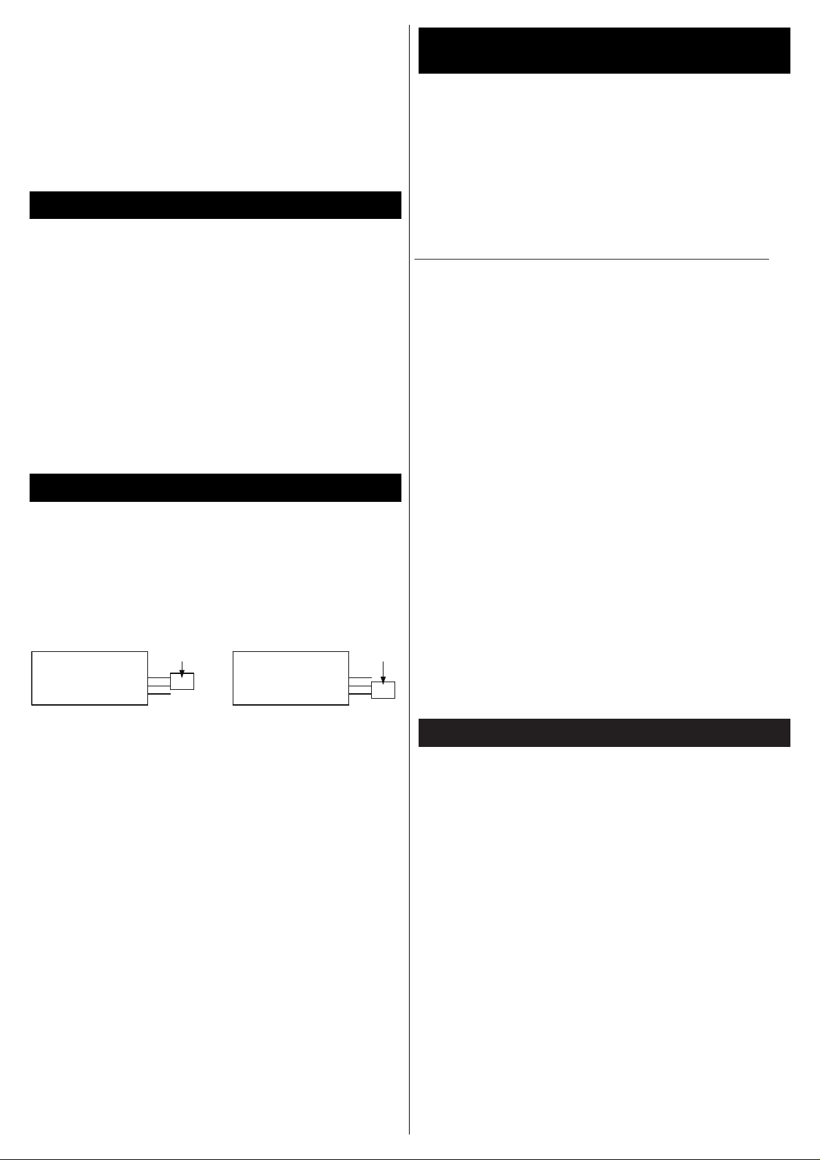
BATTERY SETUP MODE
With the battery unplugged from the ESC, position the ESC with the
label facing up.Connect the jumper on the end of the ESC as shown
below for the type of battery being used.
ESC OPERATION
1. Switch on the transmitter.
2. Move the throttle stick to the brake position (towards you).
3. Connect the battery to the ESC.The motor will beep 3 times.
4. Move the throttle stick to full power (away from you).The motor will
beep 5 times.
5. Move the throttle stick back to the brake position.
6.The ESC is now ready to operate.
IMPORTANT: If the speed control does not operate properly after
following the abov e set-up procedure, s witch the throttle re versing s witch
on transmitter and repeat the speed control set-up.
As a safety precaution to prevent the motor from starting when the
battery is first connected to the ESC, you will need to move the throttle
to full and off every time the ESC is switched on.
Because electric motors generate electrical noise it is critical to range
test the airplane, with the motor on, before flying. With the antenna
collapsed and a helper holding the airplane, operate the flight controls
while walking away from the airplane. You should be able to get
approximately 75' to 100' away before losing control of the airplane.
Next, check the range with the motor running at half throttle. The
range should be close to the range you got with the motor off.If it is
not, you may need to mov e the receiver, receiver antenna servo leads
or speed control to a different location.
Problem: Motor and receiver do not work.
1. Make sure motor battery is charged.
2. The plug between motor battery and ESC may not be making contact.
3. Check that the ESC plug is correctly plugged into the receiver.
4. Unplug the ESC from the receiver and plug a receiver battery into
the receiver. Does the radio work now? If it does, the problem may
be the ESC and requires servicing.
Problem:The ESC runs but cannot be controlled.
1. Make sure the ESC is plugged into the correct slot in the receiver.
2. Check that the transmitter is adjusted properly.
SPEED CONTR
OL WORKS (BUT O
THER PROBLEMS EXIST)
Problem: Receiver glitches or stutters while motor is running.
1. The motor capacitors are not installed correctly or have broken.
2. Receiver is mounted too close to the ESC.
3. The receiver antenna is routed too close to the motor battery, ESC
or wires.
4. The motor battery/ESC plugs do not fit tightly.
Problem: Motor quits after only a few minutes of running.
1. The prop on the motor may be too large, causing high current draw
and overheating the speed control.The thermal cutoff is switching
the motor off.
2. The motor may be damaged (bent shaft, tight bearing or shorted
winding) causing high current draw.
3. The ESC may need more cooling air flowing over it.
Problem: Motor runs backwards.
1. The ESC is wired to the motor backwards.
SERVICE PROCEDURES:
Please Note: ESC’s that operate normally when received will be
charged a minimum service fee and return shipping charges. Before
sending your ESC in for service, it is important that you review the
Troubleshooting Guide on this instruction sheet.The ESC may appear to
have f ailed when other problems e xist in the system–such as a def ectiv e
transmitter, receiver or servo, or incorrect adjustments/installation.
• Hobby dealers are not authorized to replace ESCs thought to
be defective.
• Do not cut the input wires or switch harness of the ESC before
sending it for service.A fee will be charged for cut wires which must
be replaced for testing.
Great Planes warrants this product to be free from defects in materials and workmanship
for a period of 180 days from the date of purchase. During that period, we will repair or
replace, at our option, any product that does not meet these standards. You will be
required to provide proof of purchase date (receipt or invoice). If, during the warranty
period, your ESC shows defects caused by abuse, misuse, or accident, it will be repaired
or replaced at our option, at a service charge not greater than 50% of the current retail list
price. Be sure to include your daytime telephone number in case we need to contact you
about your repair.This warranty does not cover components worn by use, application of
reverse voltage, cross connections, poor installation, subjection of components to foreign
materials, any alterations to wires, or tampering. In no case shall our liability exceed the
original cost of the product.Your warranty is voided if:
• You apply re verse voltage to the ESC by connecting the motor battery pack backwards
or plugging the motor wires into the motor battery pack.
• You allow any wires to become frayed which could cause a short.
• You use more than 8 cells (1.2 volts per cell) in the motor battery pack.
• You tamper with any of the electronic components.
• You allow water, moisture, or any other foreign material onto the PC board.
Under no circumstances will the purchaser be entitled to consequential or incidental
damages.This warranty gives you specific legal rights, and you ma y also hav e other rights
which vary from state to state. If you attempt to disassemble or repair this unit
yourself it may void the warranty.
For service to your ElectriFly C-7 Nano and C-12 Micro ESC, either in or out of warranty,
send it post paid and insured to:
Hobby Services
3002 N. Apollo Drive Suite 1
Champaign, Illinois 61822
Attn: Service Depar tment
Phone: (217) 398-0007 9:00 am-5:00 pm Central Time M-F
E-mail:
hobbyservices@hobbico.com
Internet Address:
www.electrifly.com
180 DAY LIMITED WARRANTY
TROUBLESHOOTING GUIDE
SPEED CONTROL DOES NOT WORK
STEP 6
SPEED CONTROL SETUP
STEP 5
TRANSMITTER ADJUSTMENTS
Entire Contents © Copyright 2005 GPMZ0314 For GPMM2005 & 2015 V1.0
Jumper
ESC Label SideESC Label Side
Jumper
NiCd/NiMH
(Light will stay on)
LiPo
(Light will blink)
 Loading...