

Page 1
™
Brushless Electronic Speed Controls
ElectriFly’s Silver Series line of ESCs are designed for no-frill, quick
plug-and-play convenience for controlling brushless motors. All
feature the Safe-Start function, which prevents accidental propeller
rotation until the ESC is deliberately “armed”. NiCd, NiMH, and LiPo
compatibility is also included, plus a high-power battery eliminator
circuit (BEC). A thermal protection system will automatically stop
motor rotation if ESC temperatures reach extreme levels, and a brake
function can be manually switched on or off. Radio, battery, and
motor connectors are all factory installed.
IMPORTANT PRECAUTIONS
Read and follow these precautions carefully before use.
• NEVER use more than the specified voltage on the ESCs input.
• ALWAYS mount the ESC in a position where air can freely flow
across it during operation.
• ALWAYS turn on the transmitter before connecting the battery to
the ESC.
• ALWAYS disconnect the battery from the ESC when not in use.
• ALWAYS remove the propeller from the motor when working on
the model!
• ALWAYS observe that a propeller might unexpectedly rotate
anytime that power is applied to the ESC, which could cause severe
injury! Never get near the propeller!!
• Make sure the input battery is fully charged before connecting to
the ESC, so the low voltage cutoff feature can function properly.
• Do not attempt to use Silver Series ESC with brushed motors.
• Do not allow water, moisture or any foreign material onto the ESCs
PC board.
• Use heat-shrink tubing to insulate any bare wires between the
motor battery and ESC, and from the ESC to the motor to prevent a
short circuit.
• Allow the ESC to cool before touching and between flights.
• Keep out of reach of children.
• ElectriFly is not responsible for incidental damage or personal
injury as a result of misuse of this product.
BATTERY ELIMINATOR CIRCUIT (BEC)
The built-in Battery Eliminator Circuit allows the ESC’s battery to also
supply power to the receiver and servos, eliminating the need for a
separate receiver battery. Refer to the specification chart at the end of
this manual for the BEC current ratings for each Silver Series ESC.
It’s very IMPORTANT to understand that BEC circuits are rated
to handle only a certain amount of current, power, and heat. If such
limits are exceeded the ESC might reset itself, automatically returning
throttle control back to minimum! This could happen if too many
servos are used or if using servos which draw high current (high
torque or digital servos), and is especially important to know when
flying extreme 3D maneuvers which require all servos to be
activated very rapidly at the same time. If a BEC reset occurs, only
the throttle channel will be affected – control of all other surfaces will
not be interrupted. By simply “re-arming” the throttle channel (see
“STEP 6 - ESC SETUP”) while in flight you should be able to re-gain
throttle control very quickly.
It might be hard to determine exactly how much current is being
demanded through the BEC circuit. As a general guide, refer to the
chart below to determine approximately how many servos can be used
with the different size Silver Series ESCs. Remember, this is only an
approximation! More extreme setups (with very high powered digital
servos, for example) will be more demanding on the BEC circuit.
SS-8 & SS-12
Speed Controls
Micro or nano size
analog servos
Micro or nano size
high torque or
digital servos
SS-25, SS-35, SS-45 &
SS-45D Speed Controls
Standard size
analog servos
Standard size
high torque or
digital servos
Micro or nano
size servos
If you experience unwanted throttle resets, it may be necessary to (a)
reduce the number of servos in your aircraft, (b) use less powerful
servos, (c) disable the ESC’s built-in BEC circuit (described below),
and instead power the receiver and servos with a separate receiver
battery, or (d) disable the ESC’s built-in BEC circuit, and power the
receiver with a stand-alone BEC circuit that is rated for high power.
Up to 8 NiCd/NiMH
cells, or 7.4V LiPos
33 3
22 2
Up to 8 NiCd/NiMH
cells, or 7.4V LiPos
44
33
9-10 NiCd/NiMH cells,
or 11.1V LiPos
9-10 NiCd/NiMH cells,
or 11.1V LiPos
12 NiCd/NiMH cells,
or 14.8V LiPos
12 NiCd/NiMH cells,
or 14.8V LiPos
3
Do not use BEC
455
Page 2
DISABLING THE BEC:
(−)
ORANGE
RED (+)
BROWN (–)
LIFT PLASTIC TAB
1. Make sure that no battery is connected to the ESC’s power input.
2. Looking at the top side of the ESC’s receiver plug, using a tiny flat
bladed screwdriver, carefully raise the plastic tab in the middle
which holds the pin for the RED (+) wire. Gently pull the red wire
out of the receiver plug. Be sure to cover the bare pin with heatshrink tubing or electrical tape so that it cannot short-circuit
against other items.
3. Plug the ESC’s receiver plug into the throttle channel on the receiver.
4. Connect a fully charged receiver battery to a receiver switch
harness, and plug this into the battery slot on the receiver. In most
small electric planes a 300-600mAh NiCd or NiMH battery will be
adequate. A larger battery is recommended for larger airplanes, or
for planes using more than 4 servos.
5. Turn on the transmitter, and then the receiver’s switch harness.
Then connect the motor battery to the ESC. Reverse this order to
shut the receiver off.
STEP 1: CONNECTING THE RECEIVER
®
The best method to mount the ESC in the aircraft is with Velcro
. If
the ESC will be mounted on wood, first saturate the wood with thin CA
and allow it to dry. To mount the ESC on shrink covering, first clean
the surface with rubbing alcohol. Then, cut a small piece 1/2” x 1/2”
[12.7mm x 12.7mm] of Velcro (both hook and loop), and attach the
hard hook material to the fuselage. Clean the side of the ESC with
rubbing alcohol and attach the loop material.
If the wires are not long enough to make all necessary connections to
the ESC yet achieve good balance in the aircraft, it’s best to extend the
length of the wires to the motor (not to the battery).
STEP 4: NECESSARY TRANSMITTER SETTINGS
For proper ESC operation, it’s very important to set the transmitter’s
throttle channel adjustments, as follows:
1. Set the throttle channel’s travel adjustment (ATV, EPA or ATL)
to 100%.
2. Set the throttle trim and sub-trim to neutral or zero.
3. Set the throttle channel’s reversing switch to reverse on Futaba
transmitters. Other transmitters might require you to set the
throttle reversing switch to normal.
STEP 5: CONNECTING THE BATTERY
IMPORTANT! REMOVE THE PROPELLER FROM THE MOTOR
BEFORE CONNECTING THE BATTERY!
Firmly press the “receiver connector” into the receiver’s throttle slot
(refer to your radio’s instruction manual). The orange “signal wire”
should be in the same position as would the white wire on Futaba
servos, the blue wire on Airtronics’ “Z” connector, the yellow wire on
Hitec® servos, or the orange wire on JR® or Spektrum® servos.
Caution: An Airtronics® Servo Adapter must be used when connecting
to an old style Airtronics radio.
STEP 2: MOTOR CONNECTIONS
Silver Series ESCs have gold plated female bullet connectors installed
on each motor output lead. These connections are not polarized, so
there is no need to match the color of the ESC and motor wires. If the
motor rotates backwards, simply switch any two of the ESCs motor
connectors. Once connected, make sure all connections are insulated
electrically. Failure to do so could result in permanent damage to the
motor/ESC, and void all warranties.
STEP 3: MOUNTING THE ESC
Determine the best location for the ESC, inside or outside the fuselage.
IMPORTANT! It’s highly recommended to install the ESC so
that air can freely flow across it during operation! This is especially
important when using the maximum number of cells on the input,
when ambient temperatures are very high, when using a lot of
servos in the aircraft, or performing very active 3D maneuvers! If
the airplane’s structure doesn’t naturally allow for air to flow into
the fuselage, create vent holes fore and aft in the fuselage to allow
air to pass through and across the ESC for cooling. Do NOT pack the
ESC with foam padding as it will not allow the ESC to properly
radiate heat and likely cause a thermal shutdown.
SS-8
ESC
TO BATTERY
AND SS-12
(−)
(+)
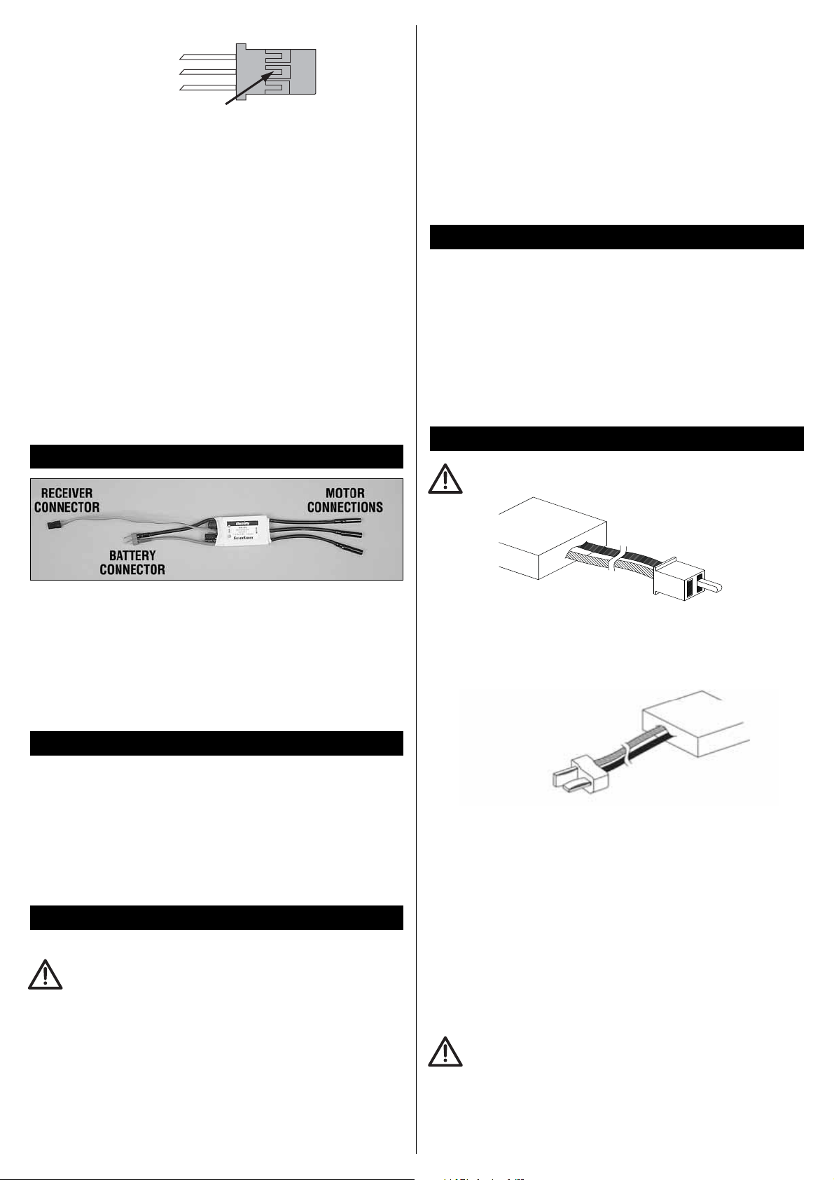
The SS-8 and SS-12 ESCs have a polarized micro connector installed,
to connect the ESC to the battery (note the exposed terminal is
negative polarity).
SS-25, SS-35
DEANS ULTRA
MALE CONNECTOR
AND SS-45
RED
(+)
ESC BATTERY LEAD
ESC
BLACK
All other Silver Series ESCs have a Deans® Ultra Plug® male battery
connector like shown above.
Make sure the polarity of the battery’s connector matches the polarity
of the ESC’s connector! Connect the red (+) leads together, and the
black (-) leads. NEVER allow a battery’s red (+) and black (-) wires to
touch as permanent damage will result and void all warranties.
LOW VOLTAGE CUTOFF: All Silver Series ESCs include a low-voltage
cutoff feature that stops motor rotation if the battery’s voltage drops
too low. This protects the battery from damage. If this activates,
power will still be supplied to the receiver and all control surfaces
except throttle, so you can maintain control of the aircraft.
It’s IMPORTANT that the battery is fully charged before being
connected to the ESC. The ESC will automatically set the low voltage
cutoff point based on the voltage of the battery as soon as it is
connected, multiplied by 0.67. For example, if the battery has only 50%
full charge when connected, the ESC will set a low voltage cutoff that is
too low. So make sure the battery is fully charged prior to every use.
Page 3

STEP 6: ESC SETUP
BRAKE FUNCTION: The factory default brake setting is “off”. Skip to
the “ESC OPERATION” section below if you want to keep this setting.
To turn the brake “on”:
1. Move the throttle stick to full throttle, turn on the transmitter and
connect the battery to the ESC.
2. After 5 seconds the motor will beep twice.
3. Move the throttle stick to the off position (towards you). The motor
will beep twice.
4. Again move the throttle stick to full power. The motor will beep
twice to confirm the brake is now “on”.
5. Move the throttle stick back to off. The motor will now beep four
times indicating the motor is “armed”.
To turn the brake off, repeat the above process. This time the motor
will only beep once with each stick movement, but will beep four times
again at the end to indicate the ESC is armed.
Once the brake is set, it does not require resetting after the ESC has
been switched off.
ESC OPERATION:
1. Turn the transmitter’s power on.
2. Move the throttle stick to the off or brake position (towards you).
3. Connect the battery to the ESC. The motor will beep to indicate the
brake setting (once for off, twice for on).
4. Move the throttle stick to full. The motor will again beep once or
twice to indicate the brake setting.
5. Move the throttle stick to off or brake and the motor will beep four
times. The ESC is now “armed”.
If the ESC does not operate properly or makes a low pitched beeping
sound following the above setup procedure, disconnect the battery
from the ESC, reverse the throttle setting on the transmitter and repeat
the ESC setup.
SAFE-START: As a safety precaution to prevent the motor from
rotating when the battery is first connected, you must “arm” the ESC
every time you connect the battery. The propeller will NOT rotate until
the ESC is armed. To arm the ESC, move the throttle stick to full
position, then back to off (or brake). Now the motor will rotate
anytime the throttle stick is advanced away from the off position!
Care must be exercised when near the model’s propeller!
NOTE: The “Silver Series” line of brushless electronic speed
controls include many built-in safety features. One such feature
COULD POSSIBLY CAUSE THE BRUSHLESS MOTOR TO STOP
ROTATING when the transmitter’s throttle stick is at an extremely
low position and/or if rotation of the brushless motor is impeded
or obstructed in some way. This is NORMAL, as the ESC is
detecting that a problem possibly exists with the motor and/or
speed control. Rotation of the motor is stopped to protect the
speed control from possible damage.
WARNING!! If the ESC and motor have already
been armed and the motor has been rotating normally, yet after
moving the throttle stick to near minimum the motor suddenly
ceases to rotate normally even if the throttle stick is advanced
above minimum throttle, DO NOT PLACE YOUR HANDS NEAR
THE PROPELLER!! FAILURE TO OBEY THIS WARNING COULD
RESULT IN PERSONAL INJURY!!
From this point, moving the throttle stick up, even to full throttle,
might not cause the motor to rotate BUT THE MOTOR IS STILL
ARMED AND ACTIVE DURING THIS TIME!! To regain control of
the motor, move the throttle stick to absolute minimum throttle
position and then advance the throttle stick upwards once again.
Alternatively, you can disconnect the battery from the ESC, and
then reconnect the power source and re-arm the system.
NEVER get near the propeller if the speed control is connected to
input power! ALWAYS make sure the throttle stick is at minimum
position before attempting to disconnect the battery from the
speed control! ElectriFly is not responsible for incidental damage
or personal injury as a result of misuse of this product.
STEP 7: RANGE TEST
Because electric motors generate electrical noise, it’s critical to range
test the airplane with the motor on, before flying. With the antenna
collapsed and a helper holding the airplane, operate the flight controls
while walking away from the airplane. You should be able to get
approximately 75 to 100 feet away before losing control of the
airplane’s surfaces. Next, check the range with the motor running at
half throttle. The range should be close to the range you got with the
motor off. If it is not, you may need to move the receiver, receiver
antenna, servo leads or the speed control to a different location.
TROUBLESHOOTING GUIDE
Problem: Motor and Rx do not work.
• Make sure the motor battery is fully charged.
• Make sure good contact is being made between the motor battery
and ESC, and from the ESC to the receiver.
• Try powering the receiver directly from a separate Rx battery…if the
receiver now works, the problem may be the ESC and require
servicing.
Problem: The ESC functions but can’t be controlled.
• Make sure the ESC is plugged into the receiver’s throttle slot.
• Make sure the Tx is properly adjusted.
Problem: The receiver glitches or stutters while the motor is running.
• The receiver or its antenna is mounted too closely to the ESC, motor
battery, or power wires.
• Make sure all electrical connections fit snugly.
Problem: The motor stops after only a few minutes of rotation, but
all other surfaces in the aircraft can still be controlled.
• The propeller might be too large causing high current draw, and the
ESCs temperature protection function is stopping motor rotation
automatically.
• Make sure the motor is not damaged (bent shaft, tight bearing, etc.)
causing high current draw.
• The ESC may need more cooling air flowing over it.
• Are too many servos being used in the model, or servos which are
drawing too much power?
• Refer to the gray box at the end of STEP 6 regarding extreme low
throttle settings.
Page 4

SERVICE PROCEDURES
ESCs that operate normally when received by Hobby Services will be
charged a minimum service fee and return shipping charges. Before
sending your ESC in for service, it is important that you review the
“Troubleshooting Guide” on this instruction sheet. The ESC may
appear to have failed when other problems exist in the system – such
as a defective transmitter, receiver or servo, or incorrect adjustments/
installation.
• Hobby dealers are not authorized to replace ESCs thought to
be defective.
• Do not cut the input wires of the ESC before sending it for service. A
fee will be charged for cut wires which must be replaced for testing.
180-DAY LIMITED WARRANTY (USA & CANADA ONLY)
Great Planes® warrants this product to be free from defects in
materials and workmanship for a period of 180 days from the date of
purchase. During that period, we will repair or replace, at our option,
any product that does not meet these standards. You will be required
to provide proof of purchase date (receipt or invoice). If, during the
warranty period, your ESC shows defects caused by abuse, misuse or
accident, it will be repaired or replaced at our option, at a service
charge not greater than 50% of the current retail list price. Be sure to
include your daytime telephone number in case we need to contact
you about your repair. This warranty does not cover components worn
by use, application or reverse voltage, cross connections, poor
installation, subjection of components to foreign materials, any
alterations to wires or tampering. In no case shall our liability exceed
the original cost of the product.
Your warranty is voided if:
• You apply reverse voltage to the ESC by connecting the motor
battery backwards.
• You allow any wires to become frayed which could cause a short.
• You use more than the rated number of cells in the motor battery.
• You tamper with any of the electronic components.
• You allow water, moisture or any other foreign material onto the PC
board.
Under no circumstances will the purchaser be entitled to consequential
or incidental damages. This warranty gives you specific legal rights,
and you may also have other rights which vary from state to state. If
you attempt to disassemble or repair this unit yourself it may void
the warranty.
For service to your ElectriFly ESC, either in or out of warranty, send it
post paid and insured to:
Hobby Services
3002 N. Apollo Dr. Suite 1
Champaign, IL 61822
(217) 398-0007
E-Mail: hobbyservices@hobbico.com
Internet Address: www.electrifly.com
SPECIFICATIONS
SS-8 SS-12 SS-25
Input Volts: 6-12 NiCd/NiMH
2-4 LiPo (20V max w/o BEC)
Output Current:
BEC:
Max. Power:
Operating Freq.:
On Resistance:
Brake:
Low Volts Cutoff:
Thermal Cutoff:
Dimensions:
Weight: 0.39oz. (11g)
Input Volts: 6-12 NiCd/NiMH
BEC: 5V / 2.0A 5V / 2.0A 5V / 2.0A
Max. Power: 350 watts 500 watts 500 watts
Operating Freq.: 8.5kHz 8.5kHz 8.5kHz
On Resistance: 0.01 ohms 0.008 ohms 0.008 ohms
Brake: on / off on / off on / off
Low Volts Cutoff: battery volts x 0.67 battery volts x 0.67 battery volts x 0.67
Thermal Cutoff: 230°F (110°C) 230°F (110°C) 230°F (110°C)
Dimensions: 2.0 x 0.31 x 1.02" (52 x 8 x 26mm) 2.76 x 0.39 x 1.30" (70 x 10 x 33mm) 2.76 x 0.39 x 1.30" (70 x 10 x 33mm)
Weight: 1.13oz. (32g) 1.76oz. (50g) 2.26oz. (64g)
Entire Contents © 2009 GPMZ0309
8A cont. max (10A surge) 12A cont. max (15A surge) 25A cont. max (28A surge)
5V / 1.5A 5V / 1.5A 5V / 2.0A
100 watts 150 watts 250 watts
8.5kHz 8.5kHz 8.5kHz
0.05 ohms 0.03 ohms 0.015 ohms
on / off on / off on / off
battery volts x 0.67 battery volts x 0.67 battery volts x 0.67
230°F (110°C) 230°F (110°C) 230°F (110°C)
1.18 x 0.24 x 0.79" (30 x 6 x 20mm) 1.30 x 0.24 x 0.91" (33 x 6 x 23mm) 1.58 x 0.31 x 1.02" (40 x 8 x 26mm)
SS-35 SS-45 SS-45D
2-4 LiPo (20V max w/o BEC)
35A cont. max (40A surge) 45A cont. max (50A surge) 45A cont. max (50A surge)Output Current:
6-12 NiCd/NiMH
2-4 LiPo (20V max w/o BEC)
0.49oz. (14g)
6-12 NiCd/NiMH
2-4 LiPo (20V max w/o BEC)
6-12 NiCd/NiMH
2-4 LiPo (20V max w/o BEC)
0.92oz. (26g)
7-14 NiCd/NiMH
4 LiPo (20V max w/o BEC)
 Loading...