

Page 1
SS-60 and SS-80SS-60 and SS-80
High Voltage Brushless Electronic Speed ControlsHigh Voltage Brushless Electronic Speed Controls
ElectriFly’s Silver Series 60 amp and 80 amp ESCs are designed for high power, plug-and-play convenience for controlling
brushless motors in large electric aircraft. Both feature the Safe-Start function, ON/OFF brake, NiCd, NiMH, and LiPo compatibility,
plus a thermal protection system. The control circuits are isolated from the power circuit by a custom optical circuit, to prevent
unwanted motor noise from adversely affecting the radio system. A universal radio connector, Star
connectors for the motor are factory-installed. Additional custom features can be set with the Silver Series Programming Card
available separately (GPMM1895).
™
Plug, and gold-plated bullet
!
IMPORTANT PRECAUTIONS
Read and follow these precautions
carefully before using.
● ALWAYS observe that a propeller might unexpectedly rotate
anytime that power is applied to the ESC, which could cause
severe injury! Never get near the propeller!!
● NEVER use more than the specified voltage on the
ESC’s input.
● ALWAYS mount the ESC in a position where free air can
fl ow across it during operation.
● ALWAYS turn on the transmitter before connecting the
battery to the ESC.
● ALWAYS disconnect the battery from the ESC when not
in use.
● ALWAYS remove the propeller from the motor when working
on the model.
● Make sure the input battery is fully charged before
connecting to the ESC, so the low voltage cutoff feature can
function properly.
● Do not attempt to use a Silver Series ESC with
brushed motors.
● Do not allow water, moisture or any foreign material onto
the ESC’s PC board.
● Use heat-shrink tubing to insulate any bare wires between
the motor battery and ESC, and from the ESC to the motor,
to prevent a short circuit.
● Allow the ESC to cool before touching and between fl ights.
● Keep out of reach of children.
● ElectriFly is not responsible for incidental damage or
personal injury as a result of misuse of this product.
1
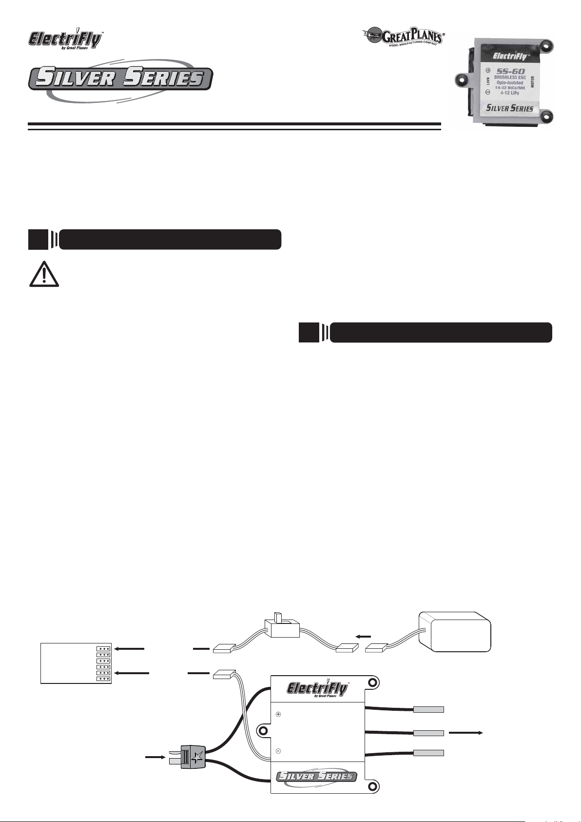
1. Firmly press the “receiver connector” into the receiver’s
throttle slot (refer to your radio’s instruction manual). The
orange “signal wire” should be in the same position as would
the white wire on Futaba
Airtronics
the orange wire on JR
An Airtronics Servo Adapter must be used when connecting to
an old style Airtronics radio. (See sketch below.)
2. Because the SS-60 and SS-80 do not include a built-in
battery eliminator circuit (BEC), it will be necessary to connect
a separate battery to power the receiver and other on-board
equipment (servos, etc). Make sure this battery is fully charged
before use. It may be desirable to install a switch harness
between this battery and the receiver. For larger airplanes, or
those using larger servos or digital servos, a receiver battery
with a high rated capacity is recommended.
3. To operate the receiver, fi rst turn on the transmitter, then the
receiver switch harness, then connect the motor battery to the
ESC. Reverse the order to shut the receiver off.
CONNECTING TO THE RECEIVER
®
®
’ “Z” connector, the yellow wire on Hitec® servos, or
and Tactic® servos, the blue wire on
®
or Spektrum® brand servos. Caution:
BATTERY
Receiver
THROTTLE
Connect main
motor battery
to Star Plug
To receiver
battery slot
Receiver
Connector:
To receiver
throttle slot
Switch
Harness
SS-60 or SS-80
BATT
BRUSHLESS ESC
Opto-Isolated
14-32 NiCd/MH
4-12 LiPo
Receiver
Battery
Connect to
brushless
motor leads −
MOTOR
SS-60 = 4mm
SS-80 = 6mm
Page 2
2
MOTOR CONNECTIONS
4
NECESSARY TRANSMITTER SETTINGS
Each of the three motor leads is made of high-quality 12 or 14
gauge, silicone insulated wire with a gold-plated female bullet
connector on the end. These connections are not polarized,
so there is no need to match the color of the ESC and motor
wires. If the motor rotates backwards, simply switch any two
of the ESC’s motor connectors. Once connected, make sure
all connections are insulated electrically. Failure to do so could
result in permanent damage to the motor/ESC, and void all
warranties.
The SS-60 includes 4mm female bullet connectors. The SS-80
includes 6mm female bullet connectors. If the connectors on
the ESC do not properly match those on the motor, an adapter
for each wire might be necessary. ElectriFly offers various
bullet connector adapters, which can be found at local retailers
as follows:
Part number Description
GPMM3114 Great Planes Gold Plated Bullet
Connector Male 4mm (3 per package)
GPMM3116 Great Planes Gold Plated Bullet
Connector Male 6mm (3 per package)
GPMM3118 4mm Male to 6mm Female Bullet
Adapter (3 per package)
GPMM3119 6mm Male to 4mm Female Bullet
Adapter (3 per package)
For proper ESC operation, it’s very important to set the
transmitter’s throttle channel adjustments, as follows:
1. Set the throttle channel’s travel adjustment (ATV,EPA or
ATL) to 100%.
2. Set the throttle trim and sub-trim to neutral or zero.
3. Set the throttle channel’s reversing switch to reverse on
Futaba transmitters. Other transmitters might require you
to set the throttle reversing switch to normal.
5
The SS-60 and SS-80
ESCs are compatible
with NiCd, NiMH, or
LiPo batteries. It is not
required to setup the
ESC to recognize the
exact battery type.
CONNECTING THE BATTERY
IMPORTANT! REMOVE THE PROPELLER
FROM THE MOTOR BEFORE CONNECTING THE
BATTERY!
ESC
Star Plug
Male Connector
(+)
(–)
Red
Black
Battery Lead
3
Determine the best location for the ESC, inside or outside the
fuselage.
the better. This is especially important when using the maximum
number of cells on the input, when ambient temperatures are
very high, when using a lot of servos in the aircraft, or performing
very active 3D maneuvers! If the airplane’s structure doesn’t
naturally allow for air to fl ow into the fuselage, create vent holes
fore and aft in the fuselage to allow air to pass through and
across the ESC for cooling. Do NOT pack the ESC with foam
padding as it will not allow the ESC to properly radiate heat and
likely cause a thermal shutdown.
three #4 x 5/8” [16mm] screws with #4 washers (wood screws
for solid wood surfaces). If mounting to metal, use three 4-40
machine screws with #4 washers.
If the wires are not long enough to make all necessary
connections to the ESC yet achieve good balance in the
aircraft, it’s best to extend the length of the wires to the motor
(not to the battery).
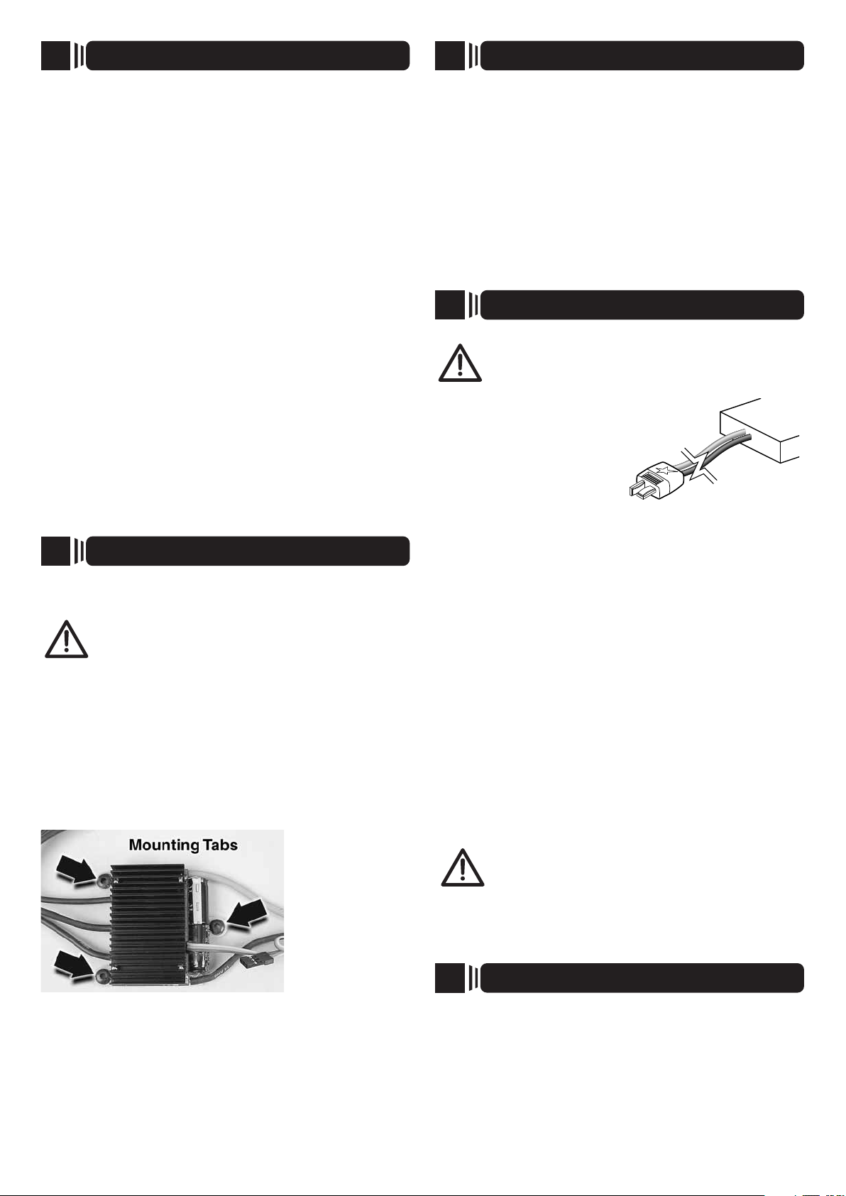
MOUNTING THE ESC
IMPORTANT! It’s highly recommended to install
the ESC so that air can freely fl ow across it during
operation! The more air which can fl ow over the ESC,
Three mounting
tabs are designed
onto the SS-60 and
SS-80 ESCs which
allows them to
be installed fi rmly
on the aircraft.
Determine the
desired location
for the ESC, and
mount fi rmly with
First, make sure the battery is FULLY charged before connecting
it to the ESC. Failure to do so will not allow the low voltage
cutoff feature to work properly (see details below). Connect the
battery to the lead on the ESC which has the Star Plug. Make
sure to observe proper polarity [red (+) leads go together, and
black (-) leads together]. NEVER allow a battery’s red (+) and
black (-) wires to touch as permanent damage will result and
void all warranties!
LOW VOLTAGE CUTOFF: The SS-60 and SS-80 ESCs include
a low-voltage cutoff feature that stops motor rotation if the
battery’s voltage drops too low (but power will still be supplied
to the receiver and servos so you can land the aircraft). This
protects the battery from damage. When the battery is initially
connected, the ESC measures the battery’s voltage and
automatically sets the low voltage cutoff based on this initial
battery voltage multiplied by 0.74. So, if the battery is NOT fully
charged when connected to the ESC, the ESC will set a low
voltage cutoff that is too low.
IMPORTANT! Make sure the battery is fully
charged prior to every use!! Failure to do so will
cause the ESC to automatically set a low-voltage
cutoff point which is too low for the battery.
6
The SS-60 and SS-80 ESCs will cause the brushless motor to
make beeps which will aid in setting up the system. Make sure the
motor is connected, but that the propeller is removed.
BRAKE FUNCTION: The factory default brake setting is “off”.
Skip to the “ESC OPERATION” section below if you want to
keep this setting. To turn the brake “on”:
ESC SETUP AND OPERATION
2
Page 3

1. Move the throttle stick to full throttle, turn on the transmitter
and connect the battery to the ESC.
2. After 5 seconds the motor will beep twice.
3. Move the throttle stick to the off position (towards you).
The motor will beep twice.
4. Again move the throttle stick to full power. The motor will
beep twice to confi rm the brake is now “on”.
5. Move the throttle stick back to off. The motor will now beep
four times indicating the motor is “armed”.
Once set, the brake function will be stored in the ESC until
changed again manually.
To turn the brake off, repeat the above process. This time
the motor will only beep once with each stick movement, but
will beep four times again at the end to indicate the ESC is
armed.
ESC OPERATION
1. Turn the transmitter’s power on.
2. Move the throttle stick to the off or brake position (towards
you).
3. Turn on the Rx switch harness, and then connect the
battery to the ESC. The motor will beep to indicate the
brake setting (once for off, twice for on).
4. Move the throttle stick to full. The motor will again beep
once or twice to indicate the brake setting.
5. Move the throttle stick to off or brake and the motor will
beep four times. The ESC is now “armed”.
WARNING!! Advancing the throttle stick will
now cause the motor to rotate! Stay clear of the
motor’s shaft!
If the ESC does not operate properly or makes a low-pitched
beeping sound following the above setup procedure, disconnect
the battery from the ESC, reverse the throttle setting on the
transmitter and repeat the ESC setup.
SAFE-START: As a safety precaution to prevent the motor from
rotating when the battery is fi rst connected, you must “arm”
the ESC every time you connect the battery. The propeller will
NOT rotate until the ESC is armed. To arm the ESC, move the
throttle stick to full position, then back to off (or brake). Now
the motor will rotate anytime the throttle stick is advanced
away from the off position! Care must be exercised when
near the model’s propeller!
WARNING!! If the ESC and motor have already
been armed and the motor has been rotating normally,
yet after moving the throttle stick to near minimum
the motor suddenly ceases to rotate normally even if
the throttle stick is advanced above minimum throttle, DO NOT
PLACE YOUR HANDS NEAR THE PROPELLER!! From this
point moving the throttle stick up - even to full throttle - might not
cause the motor to rotate BUT THE MOTOR IS STILL ARMED
AND ACTIVE DURING THIS TIME!!
To regain control of the motor, move the throttle stick to absolute
minimum throttle position and then advance the throttle stick
upwards once again. Alternatively, you can disconnect the
battery from the ESC, and then re-connect the power source
and re-arm the system. This condition might occur if the ESC
determines that a problem exists with the motor and/or speed
control, or if something obstructs normal rotation of the motor.
The ESC will completely stop the rotation of the motor to
protect the speed control from possible damage. NEVER get
near the propeller if the speed control is connected to input
power! ALWAYS make sure the throttle stick is at minimum
position before attempting to disconnect the battery from the
speed control!
7
Because electric motors generate electrical noise, it’s critical
to range test the airplane before fl ight with the motor on. With
the Tx antenna collapsed and a helper holding the airplane,
operate the fl ight controls while walking away from the airplane.
You should be able to get approximately 75 to 100 feet [22-30m]
away before losing control of the airplane’s surfaces. Next,
check the range with the motor running at half throttle. The
range should be close to the range you got with the motor off. If
it is not, you may need to move the receiver, receiver antenna,
servo leads or the speed control to a different location.
RANGE TEST
S
SPECIFICATIONS
Input voltage: 14-32 NiCd/MH cells, 4-12 LiPo cells (12.4-50V) 14- 32 NiCd/MH cells, 4-12 LiPo cells (12.4-50V)
BEC: no BEC circuit, opto-isolated no BEC circuit, opto-isolated
Output current: 60A continuous, 72A surge 80A continuous max., 96A surge max.
Max. output power: 3000 watts 4000 watts
Brake: ON or OFF ON or OFF
Rotation direction: Forward only* Forward only*
Timing angle: 12 degrees* 12 degrees*
Operating frequency: 8 kHz* 8 kHz*
Low voltage cutoff: Starting battery voltage x 0.74 Starting battery voltage x 0.74
On resistance: 0.004 ohms 0.002 ohms
Thermal cutoff: 230° F (110°C) 230°F (110°C)
Dimensions: 2.3 x 1.9 x 0.7 in. (58 x 48 x 18 mm) 2.4 x 2.6 x 0.7 in. (60 x 67 x 18 mm)
Weight: 3.13 oz. (89 g, w /Star Plug,
Rx plug, three 4mm bullets)
* can be adjusted with optional programming card (GPMM1895)
SS-60 SS-80
5.1oz. (145g, w/Star Plug,
Rx plug, three 6 mm bullets)
3
Page 4

OPTIONAL CARD
SILVER SERIES PROGRAMMING
CARD – GPMM1895
W
WARRANTY
Several features in the SS-60 and SS-80 ESCs can be
adjusted by using an optional Silver Series Programming Card
(GPMM1895), such as brake (ON or OFF), motor rotation
direction (forward or reverse), timing angle (12 or 20 degrees),
operating frequency (8kHz or 16kHz), or custom setting of the
low battery cutoff voltage (5.6-37.0V). It is not necessary to
have the Programming Card in order to use the basic features
of the SS-60 and SS-80 ESCs. See your local retailer for details
on how to get the Silver Series Programming Card.
T
Problem - Motor and Rx do not work: Make sure the motor
battery is fully charged. Make sure good contact is being made
between the motor battery and ESC, and from the ESC to the
receiver. Try powering the receiver directly from a separate Rx
battery…if the receiver now works, the problem may be the
ESC and requires servicing.
Problem - The ESC functions but can’t be controlled: Make
sure the ESC is plugged into the receiver’s throttle slot. Make
sure the Tx is properly adjusted.
Problem - The receiver glitches or stutters while the motor
is running: The receiver or its antenna is mounted too closely
to the ESC, motor battery, or power wires. Make sure all
electrical connections fi t snugly.
Problem - The motor stops after only a few minutes of
rotation, but all other surfaces in the aircraft can still be
controlled: The propeller might be too large, causing high
current draw, and the ESC’s temperature protection function
is stopping motor rotation automatically. Make sure the motor
is not damaged (bent shaft, tight bearing, etc.) causing high
current draw. The ESC may need more cooling air fl owing over
it. Are too many servos being used in the model, or servos which
are drawing too much power? Refer to the last paragraph in
STEP 6 and determine if something has obstructed the normal
rotation of the motor, or if the ESC has deliberately stopped
motor rotation and needs to be reset manually.
S
ESCs that operate normally when received by Hobby Services
will be charged a minimum service fee and return shipping
charges. Before sending your ESC in for service, it is important
that you review the “Troubleshooting Guide” on this instruction
sheet. The ESC may appear to have failed when other problems
exist in the system – such as a defective transmitter, receiver
or servo, or incorrect adjustments/installation.
TROUBLESHOOTING GUIDE
SERVICE PROCEDURES
● Hobby dealers are not authorized to replace ESCs
thought to be defective.
● Do not cut the input wires of the ESC before sending
it for service. A fee will be charged for cut wires which
must be replaced for testing.
Great Planes warrants this product to be free from defects
in materials and workmanship for a period of 180 days from
the date of purchase. During that period, we will repair or
replace, at our option, any product that does not meet these
standards. You will be required to provide proof of purchase
date (receipt or invoice). If, during the warranty period, your
ESC shows defects caused by abuse, misuse or accident, it
will be repaired or replaced at our option, at a service charge
not greater than 50% of the current retail list price. Be sure to
include your daytime telephone number in case we need to
contact you about your repair. This warranty does not cover
components worn by use, application or reverse voltage, cross
connections, poor installation, subjection of components to
foreign materials, any alterations to wires or tampering. In no
case shall our liability exceed the original cost of the product.
Your warranty is voided if:
● You apply reverse voltage to the ESC by connecting
the motor battery backwards.
● You allow any wires to become frayed which could
cause a short.
● You use more than the rated number of cells in the
motor battery.
● You tamper with any of the electronic components.
● You allow water, moisture or any other foreign
material onto the PC board.
Under no circumstances will the purchaser be entitled to
consequential or incidental damages. This warranty gives you
specifi c legal rights, and you may also have other rights which
vary from state to state. If you attempt to disassemble or
repair this unit yourself it may void the warranty.
For service to your ElectriFly ESC, either in or out of warranty,
send it post paid and insured to:
HOBBY SERVICES
3002 N. Apollo Dr. Suite 1
Champaign, IL 61822
(217) 398-0007
E-Mail: hobbyservices@hobbico.com
Internet Address: www.electrifl y.com
In the European Union, send it postpaid and insured to:
Service Abteilung Revell GmbH
Henschelstrasse 20-30
32257 Bünde Germany
Tel: 01805-110111 (nur für Deutschland)
E-mail: Hobbico-Service@Revell.de
Distributed in the EU by Revell GmbH, Bünde Germany
● This product is suitable only for people of 14 years and
older. This is not a toy!
● WARNING: CHOKING HAZARD - May contain small
parts. Keep away from children under 3 years. Please
retain packaging for future reference.
Made in China Entire Contents © 2014 GPMM1850 and GPMM1860
4
 Loading...