

Page 1
Congratulations, you have just purchased the
Ammo 24mm power system components. All
the components are sold separately to allow
you to customize your power system to your
airplane.The components needed to assemble
your Ammo 24mm power system are: Ammo
24mm motor, 24mm small gear drive, small
motor mount, propeller, propeller adapter and
brushless speed control. This instr uction sheet
explains how to determine what you will need
and how to assemble each component.
AMMO 24mm PO
AMMO 24mm PO
WER SYSTEM
WER SYSTEM
by Great Planes
®
Model Stock #
24-33-2500...............GPMG5150
24-33-3180...............GPMG5155
24-33-3500...............GPMG5160
24-33-4040...............GPMG5165
24-33-4875...............GPMG5170
24-45-2350...............GPMG5175
24-45-2900...............GPMG5180
24-45-3790...............GPMG5185
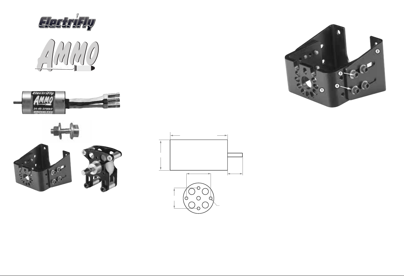
The Ammo motors are labeled to provide the
most information at a glance.For example, the
24-45-2350kV is 24mm in diameter, 45mm
long and has a kV (rpm-per-volt) of 2350 rpm.
Motor Output Shaft
Diameter x Length: 3x11.7mm [0.12" x 0.48"]
Weight (33mm): 67g [2.4oz.]
Weight (45mm): 101g [3.6oz.]
MOTORS
The ElectriFly Brushless Small Motor Mount
combines ease of installation with the
adjustability to fit most motor applications.
1. Front Plate (1)
2. Back Plate (1)
3. 4-40x1/4" SHC Screw (8)
4. #4 Flat Washer (8)
Not Shown:
5. 3x8mm SHC Screw (4)
6. 3mm Flat Washer (4)
BRUSHLESS SMALL MOTOR MOUNT
™
™
OR 45mm
33mm
24mm
19mm
16mm
11.7mm
3mm
MOUNTING
SCREW
Page 2
The ElectriFly Ammo motors have high kVs
meaning that they like to run at very high rpm.A
gear drive is used in order to reduce the rpm
allowing a larger, more efficient propeller to be
used. Great Planes ElectriFly offers a 24mm
Small Gear Drive (GPMG0505) with several
pinions that allow for the following gear ratios:
Low Ratio > 5:1,4.5:1, 4.3:1, 4:1,3.6:1, 3.3:1,
3.1:1, 2.8:1, 2.5:1, 2.2:1, 2:1 < High Ratio.
If you use a prop that is too small with a gear
ratio that is too low, the motor will draw very
little current and the prop will turn at too low of
an rpm to produce any usable power. The
higher the gear ratio, the smaller the prop will
need to be and the higher the rpm will be. If the
gear ratio is too high for the prop used, the
motor will draw excessiv e current and ov erheat.
The included chart, on the inside of the header
card, shows the motor/prop/gear ratios that
have been tested and found to work well.
The 24mm Small Gear Drive is designed to fit
the Great Planes Small Motor Mount
(GPMG1250).
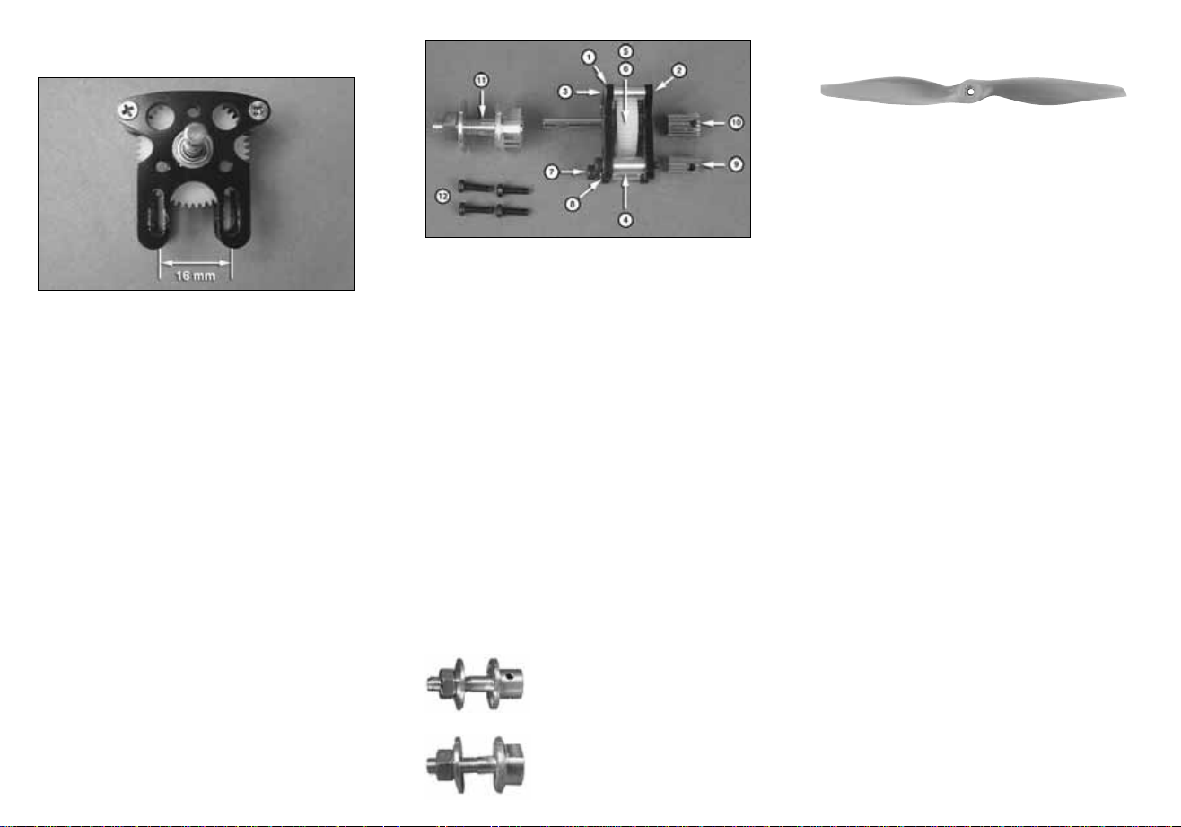
GEARBOX
1. Aluminum Front Plate (1)
2. Aluminum Back Plate (1)
3. 2.5x17mm FH Mach Screw (2)
4. 5.5x11mm Alum Spacer (4)
5. 40 T ooth Spur Gear (1)
6. 50 T ooth Spur Gear (1)
7. 3x20mm SHC Screw (2)
8. 3mm Flat Washer (2)
9. 11 Tooth Pinion Gear (1)
10. 16 Tooth Pinion Gear (1)
11. 4mm Collet Prop Adapter (1)
12. 3x6mm Machine Screw (4)
There is a wide selection of propellers
available for electric use. The 24mm motors
use high performance electric props such as
the APC E-Series props. The larger the
propeller used, the more current your motor
will draw. The smaller the propeller, the less
current the motor will draw.
Shown are a few of the recommended electric
props. Due to the large range of propellers
and the constant addition of new sizes, visit
our web sites at www.electrifly.com and
www.greatplanes.com for the most up-todate listing of electric type props.
PROPELLERS
The 24mm Small Gear Drive uses a 4mm
prop adapter. If you will be using the Ammo
24mm Motor without a gear drive, it requires a
3mm prop adapter (GPMQ4959).
PROPELLER ADAPTERS
GPMQ4930 3mm Set Screw Type
GPMQ4936 4mm Set Screw Type
APCQ4103.............7x5 Electric
APCQ4110.............8x4 Electric
APCQ4115.............8x6 Electric
APCQ4119.............9x7.5 Electric
APCQ4120...........10x5 Electric
APCQ4123...........10x7 Electric
APCQ4128...........11x7 Electric
APCQ4130...........12x6 Electric
APCQ4133...........12x8 Electric
APCQ4136...........12x10 Electric
APCQ3065...........13x6.5 Electric
GPMQ4959 3mm Collet Type
GPMQ4965 4mm Collet Type
Page 3

BATTERIES: CHEMISTRY
The Ammo Motor/Silver Series ESC combination
can use NiMH or LiPo batteries.Typically, NiMH
batteries are heavier but much cheaper for the
same capacity as LiPo batteries. If you want a
very light, high-performance airplane, you might
want to use LiPo batteries, but if weight is not a
concern, then NiMH batteries might be for you.
BATTERIES: NUMBER OF CELLS
Cells can be connected in series or in parallel.
Usually batteries are labeled as 8-cell NiMH or
3-cell LiPo .This means the cells are connected in
SERIES (S). Arranging batteries in series gives
you more power (higher voltage).
• Each NiMH cell has 1.2V, so an 8-cell
NiMH battery has 1.2x8 = 9.6V
• Each LiPo battery has 3.7V, so a 3-cell
LiPo battery has 3.7x3 = 11.1V
If you need a higher voltage than what is
available in the LiPo batter y line, you will need
to connect two battery packs together in series.
If you need a battery voltage of 14.8V you can
use the series Y-connector (GPMP3143) to
connect two 7.4V batteries together.
If a battery is arranged in P ARALLEL it might be
labeled as (P).Arranging the batteries in parallel
will give you more duration (more capacity).
ElectriFly offers a full line of NiMH and LiPo
batteries. Airplanes that use the Ammo 24mm
motors will typically use batteries with a capacity
of 910 to 2100mAh, with the higher capacity
batteries delivering more flying time but also
being heavier. Most of the batteries have
connectors that fit the recommended ESC.
Due to the constantly changing battery
technology, check out the ElectriFly web site at
www.electrifly.com for the most up-to-date
listing of the ElectriFly battery line.
ElectriFly Silver Series 25 (SS-25) ESC
(GPMM1820)
ELECTRONIC SPEED CONTROL (ESC)
An ESC is basically the device that controls
your motor through your radio system. Never
run any Ammo motors with a brushed ESC. It
will not work and you may damage both the
motor and the ESC. Always use a brushless
ESC.ElectriFly offers Brushless ESCs that will
work with the Ammo 24mm motors.
for 25A maximum constant current draw.
This ESC comes with 3.5mm female bullet
connectors that plug directly into the 3.5mm
male connectors installed on the Ammo 24mm
motors, so no soldering is required. Also, this
ESC comes with a Deans
®
Ultra battery
connector that matches the connectors that are
found on most batteries that it will use.
Battery # of
Stoc
k # Voltage Capacity Weight Type Cells
GPMP0604 7.4V 910mAh 2.0oz (58g) LiPo 2
GPMP0605 11.1V 910mAh 3.0oz (85g) LiPo 3
GPMP0608 7.4V 1250mAh 2.6oz (74g) LiPo 2
GPMP0609 11.1V 1250mAh 3.9oz (110g) LiPo 3
GPMP0830 7.4V 1500mAh 2.6oz (73g) LiPo 2
GPMP0831 11.1V 1500mAh 3.8oz (107g) LiPo 3
GPMP0616 7.4V 2100mAh 4.3oz (121g) LiPo 2
GPMP0617 11.1V 2100mAh 6.4oz (181g) LiPo 3
GPMP0250 8.4V 1100mAh 5.6oz (160g) NiMH 7
GPMP0251 9.6V 1100mAh 6.3oz (180g) NiMH 8
GPMP0253 12.0V 1100mAh 7.9oz (225g) NiMH 10
Page 4

Now that you have a component for your power system,
there are several different ways to select the rest of the
components of your power system.In time, experience will
help you to determine what works best for you, but an easy
way to determine what you need now is the following.
PROCEDURE #1: If you know the size of the propeller you
want to turn and the rpm, then look at the chart included in
the packaging and:
❏ 1. Find the combination in the motor/prop chart that
delivers the closest performance to what you want.
❏ 2. Note the gear ratio you need.
❏ 3. Note the recommended battery voltage.
❏ 4. Determine if you want to use LiPo or NiMH batteries
based on the desired ready-to-fly airplane weight.
Select the number of cells based on the recommended
voltage shown on the chart.
❏ 5. Determine the batter y capacity needed based on the
current draw of your system and your desired flight time.
❏ 6. Determine the ESC you need based on the system
current draw shown on the motor/prop chart. See the
ESC section.
PROCEDURE #2: If you know the approximate weight of
your airplane, including the motor and battery, and the
performance you want from it, answer the questions below
to determine the correct power system for your plane. You
may need to make more than one calculation using
different motors and battery combinations. See the battery
section for some of the battery weights for the suggested
batteries.
❏ 1. Perform the following calculation to determine the
wattage required:
• If you expect trainer-like performance then multiply
75 x Airplane Weight (lbs)
• If you expect aerobatic or high speed-like performance
then multiply 100 x Airplane Weight (lbs)
• If you expect 3D or extreme performance multiply
150 x Airplane Weight (lbs)
❏ 2. The number you get is the minimum wattage you will
need for your plane to perform as you wish.Look at the
chart and determine what combination gives you the
performance you want based on wattage and
maximum propeller size that will fit on the plane.
❏ 3. Note the gear ratio you need.
❏ 4. Note the recommended battery voltage.
DETERMINE WHA T Y OU NEED TO
BUILD YOUR POWER SYSTEM
❏ 5. Deter mine if you want to use LiPo or NiMH batteries
based on the desired ready to fly airplane weight.
Select the number of cells based on the recommended
voltage shown in the chart.
❏ 6. Determine the batter y capacity needed based on the
current draw of your system and your desired flight time.
❏ 7. Determine the ESC you need based on the system
current draw.
In addition to these two procedures, you can also visit the
Great Planes ElectriFly web site for descriptions of the power
systems recommended for our line of electric and glow
airplanes as well as more detailed explanation on the subject.
UNDERSTANDING MOTORS
kV (rpm/volt): This is a number that gets thrown around
quite a bit when talking electrics and it is important to know
what it is. kV is the number of rpm a motor will spin per
each volt applied (rpm/volt) under no load.
This means that basically a motor that has a kV of 1000
when connected to a 12V battery will try to spin at
12,000rpm (1000x12) under no load. Likewise a 3500kV
motor will try to spin at 42,000rpm (3500x12) under no load.
When a propeller is attached to the motor, the motor will try
to spin the prop at the rated kV. Depending on the diameter
and pitch of the propeller (the larger the diameter or higher
the pitch, the harder it is to spin), the motor’s current draw
can be increased or decreased.There are meters available
from your hobby dealer that measure current and voltage.
Because every motor has a maximum current it can take
based on its design and cooling ability, the maximum size of
propeller that can be used with each motor can be
determined.Too large of a propeller and the motor will spin at
a much lower rpm than its rated kV, causing it to draw a lot of
current and overheat. If the propeller/fan is too small, it will
require little effort (current) to turn the prop at the rated kV.
Ideally the motor should be matched with a propeller that
causes the motor to draw 80-100% of its rated maximum
constant current. Once a power system is set up, it can be
fine-tuned by adjusting the propeller size and measuring
the amount of current the motor is drawing.
Please note that the kV of a motor does not change with
voltage, but if a higher voltage is applied to the motor, it will
try to spin the same propeller at a higher rpm. This will
cause the motor to draw more current and possibly exceed
the maximum rated current of the motor.So, if a battery with
lower voltage is replaced with one with a higher voltage, it
is recommended that a smaller propeller be used to keep
the current in check. If a higher voltage battery is replaced
by a lower voltage battery, the size of the propeller can be
increased to keep the motor at its rated current.
Another possibility to fine tune the power system’s
performance is to use another motor with higher kV to
increase the current or a lower kV to lower the current.
INSTALL THE PINION GEAR
Once you have determined the
gear ratio required, the brass
pinion gear must be installed
on the motor shaft. The pinion
gear is a press fit on the motor
shaft and it will need to be
heated and pressed on. Never
force the pinion gear on the
shaft without supporting the
other end of the motor shaft. A
small wheel collar works well
for supporting the motor shaft. If you have a drill press the
motor can be placed in a vise with the motor shaft supported
on a small wheel collar. Use a small micro torch to heat the
pinion gear and use the drill chuck of the drill press to press
the pinion onto the shaft.
Note:The pinion gear uses a small set screw to secure the
pinion gear to the motor shaft. When installing the pinion
gear make sure that the flat on the motor shaft is aligned
with the set screw.
If you do not have a drill press a
small vise can also be used. Place
the motor between the jaws of the
vise with the end of the motor shaft
supported and the pinion gear
centered on the motor shaft. Heat
the pinion gear and slowly close
the jaws of the vise. You may need
to use a second wheel collar so
that the pinion gear can be pressed
on past the end of the motor shaft.
Once the pinion gear is in position on the motor shaft,
apply a drop of threadlocker to the threads of the set screw
and tighten it down on the flat of the motor shaft.
ASSEMBLE YOUR POWER SYSTEM
Page 5

REMOVAL OF THE PINION GEAR
The best method of removing the pinion gear is by heating
it with a micro torch and using a pinion puller to carefully
pull the gear off.
REPLACING THE SPUR GEAR
To remove the spur gear, loosen and remove the two
2.5x17mm flat head machine screws and 5.5mm aluminum
spacers. Remove the backplate, being careful to not lose
the 4mm bearing spacer.
MOUNT THE MOTOR T O
THE GEAR DRIVE
Loosely mount the motor to the back of the back plate with
two 3x20mm SHC screws and two 3mm flat washers.Place
a piece of notebook paper between the pinion gear and the
spur gear.Squeeze the two gears together while tightening
the two 3x20mm SHC screws. Remove the piece of paper
and the gear mesh should be set. Rotate the gears to make
sure they rotate smoothly. If they do not, slightly loosen the
gear mesh until the gears do rotate smoothly.
MOUNT THE BRUSHLESS
SMALL MOTOR MOUNT
In the center of the header card you will find the mounting
hole pattern template for the Brushless Small Motor
Mount. The Motor Mount can be attached to the firewall
using 4-40 machine screws and blind nuts installed in the
back of the firewall.Use the center lines on the template to
properly align it on the firewall.
In-runner motors that will be run direct drive or gear drive
and are mounted inside the front plate.
Press the output shaft out of the spur gear and remove the
spur gear pin.The spur gear can now be replaced. Reverse
the order to reassemble the gear drive.Be sure to use a drop
of threadlocker on the two 2.5x17mm flat head machine
screws to prevent them from loosening during operation.
Attach the Backplate to the firewall using four 4-40 machine
screws and four #4 flat washers.Note that if you are using
a gear drive you may hav e to cut a hole in the firew all for the
motor.Most motors and gear drives can be mounted to the
Front Plate using 3mm machine screws.If you are using a
different gear drive other than the Great Planes gear drive,
the hole locations may need to be modified.
Out-runner motors can be mounted inside the front plate in
some situations using three 3x8mm SHC screws, but most of
the time they will be mounted on the front of the front plate.
Page 6

Install the prop adapter on the motor shaft or gear drive
output shaft.The Brushless 24mm Gear Drive uses a 4mm
prop adapter (GPMQ4965 Collet Type or GPMQ4936 Set
Screw Type).The Ammo 24mm motors direct dr ive uses a
3mm prop adapter (GPMQ4959 Collet Type or GPMQ4930
Set Screw Type).
COLLET TYPE PROP ADAPTER INSTALLATION
Slide the prop shaft over the output shaft of the gear drive or
motor.Next slide the prop shaft retainer over the prop shaft.
Note that the hole through the retainer is tapered.Make sure
that the side with the larger diameter hole is installed first.
Install the spinner backplate (if used, not included), the
prop, prop washer and then the prop nut.Tighten the prop
nut against the prop.This will cause the tapered hole in the
prop shaft retainer to squeeze the prop shaft around the
output shaft. Carefully pull on the prop to make sure it is
securely attached to the output shaft of the gear drive.
SET SCREW TYPE PROP ADAPTER INSTALLATION
Slide the prop adapter over the output shaft of the gear
drive or motor.Align one of the set screws with the flat on
the output shaft of the gear drive. Apply a drop of Great
Planes Threadlocker (GPMR6060) to the set screw and
install it in the prop adapter, tightening it against the flat of
the gear drive output shaft. Remove the second set screw
that does not tighten onto the flat.When installing the prop
adapter onto a shaft that does not have a flat spot, tighten
both of the set screws against the shaft.Install the spinner
backplate (if used, not included), the prop, prop washer
and then the prop nut. Tighten the prop nut against the
prop. Carefully pull on the prop to make sure it is securely
attached to the output shaft of the gear drive.
Determine the distance the prop adapter needs to be from
the firewall by using the recommended distance in the
instructions or by installing the cowl and measuring the
distance from the firewall to the front of the cowl. Add
approximately 3/32" to 1/8" to the distance. Attach the
Front Plate of the motor mount to the Back Plate using the
eight 4-40x1/4" SHC screws and eight #4 flat washers,
spaced out as far as possible. A drop of threadlocker on
the screws will prevent them from coming loose.
When mounting some of the Rimfire out-runner motors you
may need to remove the brass collar and install the aluminum
spacers on the motor shaft to space the collar behind the
Front Plate to prevent it from rubbing on the Front Plate.
INST ALL THE BRUSHLESS ESC
Because most of the power systems using the 24mm
Ammo motor are drawing less than 25 amps constant, the
ElectriFly SS-25 Brushless ESC (GPMM1820) will work
well. Note that if you will be operating the motors at the
surge currents a higher current ESC will need to be
installed. Always make sure that the ESC is installed in a
location that allows plenty of cooling air to flow over it.
Follow the instructions included with the Brushless ESC to
properly install and program it.
AMMO MOTOR MAINTENANCE
Ammo brushless motors require virtually no maintenance.
There are no brushes to wear out and replace. The
precision bearings have a very long service life and should
last a very long time.The internal parts of the motor should
not require any cleaning.
IMPORTANT PRECAUTIONS
• Once the batter y is connected to the ESC, stay clear of
the motor and prop.
• DO NOT apply an input voltage that exceeds the
maximum specification of each motor.
• DO NOT apply currents to the motor that exceed the
maximum specifications of each motor.
• DO NOT allow the input connectors to accidentally touch
each other while power is applied to the motor.Make sure
all input connections are insulated electrically.
• DO NOT allow water or moisture to enter the motor, as it
can cause permanent damage to the motor and possibly
short out the attached ESC.
• DO NOT cut the coated wires from the motor.If you must
remove the bullet connectors, unsolder them.
• Allow the motor to cool after each flight.
• The motor shaft of the motor will rotate at very high rpm.
DO NOT attempt to touch the shaft while it is rotating. If
setting up the motor/ESC on the workbench, make sure
the motor is securely attached and that nothing is
attached to the motor shaft BEFORE applying power.
• Never attempt to use a damaged motor (having
mechanical or electrical defects).
• Great Planes carries a complete line of Ammo (in-runner
style) and Rimfire (out-runner style) brushless motors,
gear drives, motor mounts, prop adapters and speed
controls. For a complete list of these products, check out
our web sight at:
www.greatplanes.com
www.electrifly.com
or visit your nearest hobby shop that carries the full line of
Great Planes and ElectriFly products.
GPMZ0024 for Ammo 24mm SystemsEntire Contents Copyright © 2006
 Loading...