

Page 1
Congratulations, you have just purchased the
Ammo 20mm power system components. All
the components are sold separately to allow
you to customize your power system to your
airplane.The components needed to assemble
your Ammo 20mm power system are: Ammo
20mm motors, a 20mm stick mount gearbox,
propeller, propeller adapters and brushless
speed control. This instruction sheet explains
how to determine what you will need and how
to assemble each component.
AMMO 20mm PO
AMMO 20mm PO
WER SYSTEM
WER SYSTEM
by Great Planes
®
Model Stock #
20-30-2650...............GPMG5115
20-30-3500...............GPMG5120
20-30-4300...............GPMG5125
20-30-5200...............GPMG5130
20-40-2080...............GPMG5135
20-40-3500...............GPMG5140
20-40-4850...............GPMG5145
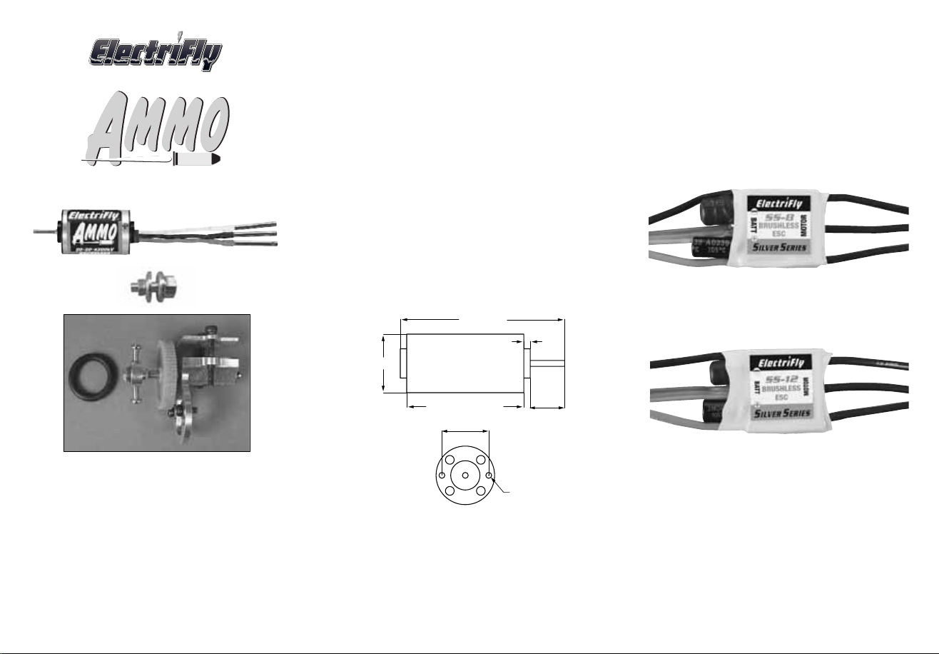
The Ammo motors are labeled to provide the
most information at a glance.For example:the
20-40-4850kV is 20mm in diameter, 40mm
long and has a kV (rpm-per-volt) of 4850 rpm.
Motor Output Shaft
Diameter and Length: 2x10mm [0.08"x0.4"]
Weight (30mm): 45g [1.6oz.]
Weight (40mm): 65g [2.3oz.]
MOTORS
An ESC is basically the device that controls
your motor through your radio system. Never
run any Ammo motors with a brushed ESC. It
will not work and you may damage both the
motor and the ESC. Always use a brushless
ESC. ElectriFly offers two Silver Series
Brushless ESCs that will work with the Ammo
20mm motors.
ELECTRONIC SPEED CONTROL (ESC)
ElectriFly Silver Series 8 (SS-8) ESC
(GPMM1800)
for 8A maximum constant current draw.
These ESCs come with 2mm female bullet
connectors that plug directly into the 2mm
male connectors installed on the Ammo
20mm motors, so no soldering is required.
Also, these ESCs come with Micro Deans
battery connectors that match the connectors
that are found on most batteries they will use.
™
™
ElectriFly Silver Series 12 (SS-12) ESC
(GPMM1810)
for 12A maximum constant current draw.
56.2mm
2.2mm
20mm
30mm
OR 40mm
16mm
11.8mm
2.5mm
MOUNTING
SCREW
Page 2
GEARBOX
The ElectriFly Ammo motors have high kVs
meaning that they like to run at very high rpm.
A gear drive is used in order to reduce the rpm
allowing a larger, more efficient propeller to be
used. Great Planes ElectriFly offers a 20mm
Stick Mount Gear Drive (GPMG0500) with
several pinions that allow for the following
gear ratios:
Low Ratio> 4.5:1, 5.3:1, 6.4:1, 8:1 <High Ratio
If you use a prop that is too small with a gear
ratio that is too low, the motor will draw very
little current and the prop will turn at too low of
an rpm to produce any usable power. The
higher the gear ratio, the smaller the prop will
need to be and the higher the rpm will be. If the
gear ratio is too high for the prop used, the
motor will draw excessiv e current and ov erheat.
The included chart, on the inside of the header
card, shows the motor/prop/gear ratios that
have been tested and found to work well.
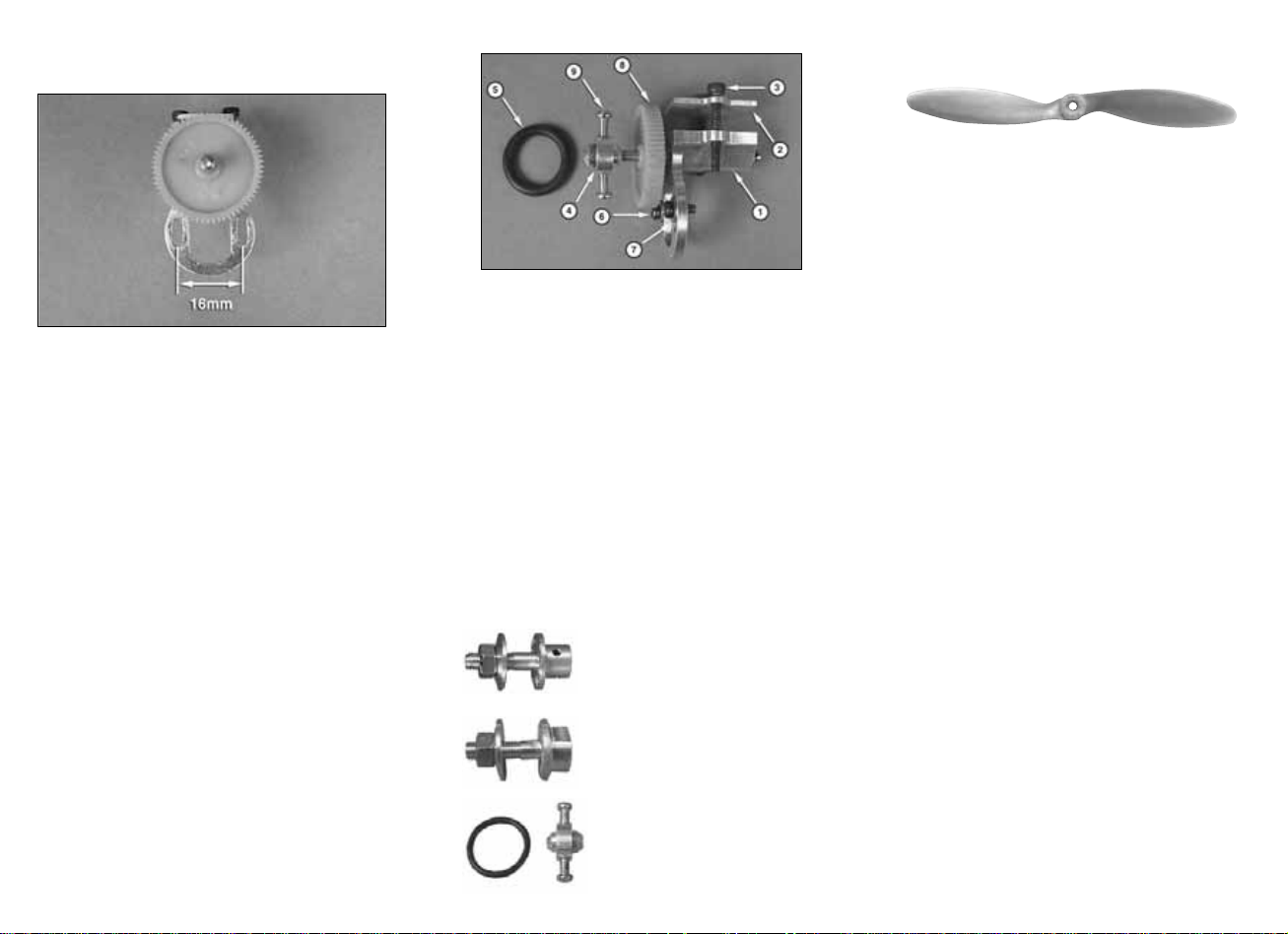
The Stick Mount Gear Drive is designed to fit
the 10mm motor mounting stick that is common
on most of today’s small park flyers.
1. Aluminum Gear Drive Body (1)
2. Aluminum Top Plate (1)
3. 2.5x20mm SHC Screw (2)
4. Prop Saver Hub (1)
5. Rubber O-Ring (1)
6. 2.5x4mm Machine Screw (2)
7. 2.5mm Flat Washer (2)
8. 64 T ooth Spur Gear (1)
9. 2.5x7mm Machine Screw (2)
PROPELLER ADAPTERS
The 20mm Stick Mount Gear Drive uses a
3mm prop adapter. If you will be using the
Ammo 20mm Motor without a gear drive it
requires a 2mm prop adapter.
GPMQ4930 3mm Set Screw Type
GPMQ4953 2mm Collet Type
GPMQ4959 3mm Collet Type
GPMQ4620 3mm Prop Saver
(Included with Gearbox)
PROPELLERS
There is a wide selection of propellers
available for electric use. The 20mm motors
use mainly low-power electric type props such
as the Great Planes PowerFlow
the APC Slo Flyer props. The larger the
propeller used, the more current your motor
will draw. The smaller the propeller, the less
current the motor will draw.
Shown are a few of the recommended electric
props. Due to the large range of propellers
and the constant addition of new sizes, visit
our web sites at www.electrifly.com and
www.greatplanes.com for the most up-todate listing of electric type props.
GPMQ6655.......10x3.5S PowerFlow
GPMQ6660.......10x4.5S PowerFlow
GPMQ6695.......11x4.5S PowerFlow
APCQ5000..........8x3.8SF Slo-Flyer
APCQ5010..........9x4.7SF Slo-Flyer
APCQ5015........10x4.7SF Slo-Flyer
APCQ5016........10x3.8SF Slo-Flyer
APCQ5017........11x3.8SF Slo-Flyer
APCQ5020........11x4.7SF Slo-Flyer
APCQ5025........11x7SF Slo-Flyer
APCQ5026........12x6SF Slo-Flyer
APCQ5027........12x3.8SF Slo-Flyer
APCQ5028........12x8SF Slo-Flyer
™
props and
Page 3

BATTERIES: CHEMISTRY
The Ammo Motor/Silver Series ESC
combination can use NiMH or LiPo batteries.
Typically, NiMH batteries are heavier but m uch
more affordable for the same capacity as LiPo
batteries. If you want a very light, highperformance airplane, you might want to use
LiPo batteries, but if weight is not a concern,
then NiMH batteries might be for you.
BATTERIES: NUMBER OF CELLS
Cells can be connected in series or in parallel.
Usually batteries are labeled as 8-cell NiMH or
3-cell LiPo .This means the cells are connected in
SERIES (S). Arranging batteries in series gives
you more power (higher voltage).
• Each NiMH cell has 1.2V, so an 8-cell
NiMH battery has 1.2x8 = 9.6V
• Each LiPo battery has 3.7V, so a 3-cell
LiPo battery has 3.7x3 = 11.1V
If you need a higher voltage than what is
available in the LiPo batter y line, you will need
to connect two battery packs together in series.
If you need a battery voltage of 14.8V you can
use the series Y-connector (GPMP3147) to
connect two 7.4V batteries together.
If a battery is arranged in P ARALLEL it might be
labeled as (P).Arranging the batteries in parallel
will provide more duration (more capacity).
ElectriFly offers a full line of NiMH and LiPo
batteries. Airplanes that use the Ammo 20mm
motors will typically use batteries with a
capacity of 340mAh to 1500mAh with the
higher capacity batteries delivering more flying
time but also being heavier. Most of the
batteries have connectors that fit the
recommended ESCs. We have also listed the
connector adapters needed when using certain
battery/SS-8 or SS-12 combinations.
Due to the constantly changing battery
technology, check out the ElectriFly web site at
www.electrifly.com for the most up-to-date
listing of the ElectriFly battery line.
Battery # of Connector
k # Voltage Capacity Weight Type Cells Adapter
Stoc
GPMP0800 7.4V 350mAh .88oz (25g) LiPo 2
GPMP0801 11.1V 350mAh 1.2oz (35g) LiPo 3
GPMP0600 7.4V 640mAh 1.3oz (37g) LiPo 2
GPMP0601 11.1V 640mAh 2.0oz (58g) LiPo 3
GPMP0604 7.4V 910mAh 2.0oz (58g) LiPo 2 GPMP3127
GPMP0605 11.1V 910mAh 3.0oz (85g) LiPo 3 GPMP3127
GPMP0608 7.4V 1250mAh 2.6oz (74g) LiPo 2 GPMP3127
GPMP0609 11.1V 1250mAh 3.9oz (110g) LiPo 3 GPMP3127
GPMP0830 7.4V 1500mAh 2.6oz (73g) LiPo 2 GPMP3127
GPMP0831 11.1V 1500mAh 3.8oz (107g) LiPo 3 GPMP3127
GPMP0065 9.6V 300mAh 2.4oz (69g) NiMH 8 GPMP3135
GPMP0067 9.6V 350mAh 2.3oz (65g) NiMH 8 GPMP3135
GPMP0071 8.4V 650mAh 3.9oz (110g) NiMH 7 GPMP3135
GPMP0072 9.6V 650mAh 4.4oz (125g) NiMH 8 GPMP3135
Page 4

Now that you have a component for your power system,
there are several different ways to select the rest of the
components of your power system.In time, experience will
help you to determine what works best for you, but an easy
way to determine what you need now is the following.
PROCEDURE #1: If you know the size of the propeller you
want to turn and the rpm, then look at the chart included in
the packaging and:
❏ 1. Find the combination in the motor/prop chart that
delivers the closest performance to what you want.
❏ 2. Note the gear ratio you need.
❏ 3. Note the recommended battery voltage.
❏ 4. Determine if you want to use LiPo or NiMH batteries
based on the desired ready-to-fly airplane weight.
Select the number of cells based on the recommended
voltage shown on the chart.
❏ 5. Determine the batter y capacity needed based on the
current draw of your system and your desired flight time.
❏ 6. Determine the ESC you need based on the system
current draw shown on the motor/prop chart. See the
ESC section.
PROCEDURE #2: If you know the approximate weight of
your airplane, including the motor and battery, and the
performance you want from it, answer the questions below
to determine the correct power system for your plane. You
may need to make more than one calculation using
different motors and battery combinations. See the battery
section for some of the battery weights for the suggested
batteries.
❏ 1. Perform the following calculation to determine the
wattage required:
• If you expect trainer-like performance then multiply
75 x Airplane Weight (lbs)
• If you expect aerobatic or high speed-like performance
then multiply 100 x Airplane Weight (lbs)
• If you expect 3D or extreme performance multiply
150 x Airplane Weight (lbs)
❏ 2. The number you get is the minimum wattage you will
need for your plane to perform as you wish.Look at the
chart and determine what combination gives you the
performance you want based on wattage and
maximum propeller size that will fit on the plane.
❏ 3. Note the gear ratio you need.
❏ 4. Note the recommended battery voltage.
DETERMINE WHA T Y OU NEED TO
BUILD YOUR POWER SYSTEM
❏ 5. Deter mine if you want to use LiPo or NiMH batteries
based on the desired ready to fly airplane weight.
Select the number of cells based on the recommended
voltage shown in the chart.
❏ 6. Determine the batter y capacity needed based on the
current draw of your system and your desired flight time.
❏ 7. Determine the ESC you need based on the system
current draw.
In addition to these two procedures, you can also visit the
Great Planes ElectriFly web site for descriptions of the power
systems recommended for our line of electric and glow
airplanes as well as more detailed explanation on the subject.
UNDERSTANDING MOTORS
kV (rpm/volt): This is a number that gets thrown around
quite a bit when talking electrics and it is important to know
what it is. kV is the number of rpm a motor will spin per
each volt applied (rpm/volt) under no load.
This means that basically a motor that has a kV of 1000
when connected to a 12V battery will try to spin at
12,000rpm (1000x12) under no load. Likewise a 3500kV
motor will try to spin at 42,000rpm (3500x12) under no load.
When a propeller is attached to the motor, the motor will try
to spin the prop at the rated kV. Depending on the diameter
and pitch of the propeller (the larger the diameter or higher
the pitch, the harder it is to spin), the motor’s current draw
can be increased or decreased.There are meters available
from your hobby dealer that measure current and voltage.
Because every motor has a maximum current it can take
based on its design and cooling ability, the maximum size of
propeller that can be used with each motor can be
determined.Too large of a propeller and the motor will spin at
a much lower rpm than its rated kV, causing it to draw a lot of
current and overheat. If the propeller/fan is too small, it will
require little effort (current) to turn the prop at the rated kV.
Ideally the motor should be matched with a propeller that
causes the motor to draw 80-100% of its rated maximum
constant current. Once a power system is set up, it can be
fine-tuned by adjusting the propeller size and measuring
the amount of current the motor is drawing.
Please note that the kV of a motor does not change with
voltage, but if a higher voltage is applied to the motor, it will
try to spin the same propeller at a higher rpm. This will
cause the motor to draw more current and possibly exceed
the maximum rated current of the motor.So, if a battery with
lower voltage is replaced with one with a higher voltage, it
is recommended that a smaller propeller be used to keep
the current in check. If a higher voltage battery is replaced
by a lower voltage battery, the size of the propeller can be
increased to keep the motor at its rated current.
Another possibility to fine tune the power system’s
performance is to use another motor with higher kV to
increase the current or a lower kV to lower the current.
INSTALL THE PINION GEAR
Once you have determined the gear ratio you need, the
brass pinion gear will need to be installed on the motor
shaft. If the brass pinion gear fits loose on the motor shaft,
the pinion gear will need to be secured to the motor shaft
using a retaining compound, such as Great Planes'
GPMA6062. For the most secure fit, roughen the motor
shaft with 320-grit to 400-grit sandpaper. Clean the motor
shaft and the inside of the pinion gear with denatured
alcohol. Apply a thin film of retaining compound on the
motor shaft and inside the pinion gear.Slide the pinion gear
on the motor shaft and allow the retaining compound to set.
Usually 1-2 hours.
If the brass pinion gear fits tight on the motor shaft it will
need to be pressed on. Never force the pinion gear on the
shaft without supporting the other end of the motor shaft. A
small wheel collar works well for supporting the motor shaft.
If you have a drill press the motor can be placed in a vice
with the motor shaft supported on a small wheel collar.Use
a small micro torch to heat the pinion gear and use the drill
chuck of the drill press to press the pinion onto the shaft.
ASSEMBLE YOUR POWER SYSTEM
Page 5

If you do not have a drill press a small vise can also be
used.Place the motor between the jaws of the vise with the
end of the motor shaft supported and the pinion gear
centered on the motor shaft. You may need to use a
second wheel collar so that the pinion gear can be pressed
on past the end of the motor shaft.
REMOVAL OF THE PINION GEAR
Whether the pinion gear is glued on or pressed on, the
best method of removing the pinion gear is by heating it
with a micro torch and using a pinion puller to carefully pull
the gear off.
REPLACING THE SPUR GEAR
The spur gear is simply pressed over a spline on the output
shaft. Due to crashes and other unfortunate mishaps, the
teeth on the spur gear may be damaged or the spur gear
may twist off of the spline. If this happens, remove the
damaged spur gear and press a new gear over the spline.
MOUNT THE MOTOR
TO THE GEAR DRIVE
Loosely mount the motor to the back of the gear drive
motor plate with two 2.5x4mm machine screws and two
2.5mm flat washers. Place a piece of notebook paper
between the pinion gear and the spur gear. Squeeze the
two gears together while tightening the two 2.5x4mm
machine screws. Remove the piece of paper and the gear
mesh is set.
MOUNT THE GEAR DRIVE
TO THE PLANE
INST ALL THE BRUSHLESS ESC
To determine which brushless ESC you will need, find the
current draw for the motor/prop/gear ratio that you are using.
If the constant current is 8 amps or less, use the ElectriFly
SS-8 (GPMM1800). If the constant current is 12 amps or
less, use the ElectriFly SS-12 (GPMM1810). Note that a
couple of the motor/prop/gear ratio combinations shown in
the chart draw 15 amps. All the motor testing to determine
the current draw, shown on the chart, was done on the
ground.When the airplane is in flight the current draw will be
slightly less.This allows the use of the ElectriFly SS-12 ESC
to be used with the motor/prop/gear ratio that draws 15
amps.If you use one of these combinations, make sure that
the ESC is installed in a location that allows plenty of cooling
air to flow over it.
Use the instructions included with the ESC to correctly
connect the ESC.
INSTALL THE PROP ADAPTER
AND PROP
The prop saver prop adapter is included with the Stick
Mount Gear Drive. If you prefer to use the collet type prop
adapter or set screw type prop adapter, you will need the:
GPMQ4959 3mm Collet-type Prop Adapter
GPMQ4930 3mm Set Screw-type Prop Adapter
PROP SAVER PROP ADAPTER INSTALLATION
To accomplish this, use a tube or socket placed over the
output shaft and against the new spur gear. Place this
assembly in a vise and press the gear over the spline.
The Great Planes Stick Mount Gear Drive is designed to
be mounted on a 10mm stick. Loosen the two 2.5x20mm
SHC screws and raise the Top Plate. Slide the Gear Drive
over the 10mm stick and tighten the two 2.5x20mm SHC
screws.Do not overtighten the screws, crushing the wood.
Install the cowl if the plane comes with one. Note that on the
prop saver hub the center protrusions have different
diameters on each side of the hub.Determine which diameter
fits the prop you are using.Then, install the prop saver hub on
the output shaft of the gear drive with the correct diameter
facing outward.Tighten the two 2.5x7mm machine screws in
the prop saver hub against the output shaft.
Page 6

Install the prop on the prop hub and secure it with a rubber
O-ring looped over both of the machine screws.
COLLET TYPE PROP ADAPTER INSTALLATION
Slide the 3mm prop shaft over the output shaft of the gear
drive.Next slide the prop shaft retainer over the prop shaft.
Note that the hole through the retainer is tapered. Make
sure that the side with the larger diameter hole is installed
first. Install the spinner backplate (if used, not included),
the prop, prop washer and then the prop nut.Tighten the
prop nut against the prop.This will cause the tapered hole
in the prop shaft retainer to squeeze the prop shaft around
the output shaft. Carefully pull on the prop to make sure it
is securely attached to the output shaft of the gear drive.
• Once the batter y is connected to the ESC, stay clear of
the motor and prop.
• DO NOT apply an input voltage that exceeds the
maximum specification of each motor.
• DO NOT apply currents to the motor that exceed the
maximum specifications of each motor.
• DO NOT allow the input connectors to accidentally touch
each other while power is applied to the motor.Make sure
all input connections are insulated electrically.
• DO NOT allow water or moisture to enter the motor, as it
can cause permanent damage to the motor and possibly
short out the attached ESC.
• DO NOT cut the coated wires from the motor.If you must
remove the bullet connectors, unsolder them.
• Allow the motor to cool after each flight.
• The motor shaft of the motor will rotate at very high rpm.
DO NOT attempt to touch the shaft while it is rotating. If
setting up the motor/ESC on the workbench, make sure
the motor is securely attached and that nothing is
attached to the motor shaft BEFORE applying power.
• Never attempt to use a damaged motor (having
mechanical or electrical defects).
• Great Planes carries a complete line of Ammo (in-runner
style) and Rimfire (out-runner style) brushless motors,
gear drives, motor mounts, prop adapters and speed
controls. For a complete list of these products, check out
our web sight at:
www.greatplanes.com
www.electrifly.com
or visit your nearest hobby shop that carries the full line of
Great Planes and ElectriFly products.
IMPORTANT PRECAUTIONS
SET SCREW TYPE PROP ADAPTER INSTALLATION
Slide the 3mm prop adapter over the output shaft of the
gear drive. Align one of the set screws with the flat on the
output shaft of the gear drive.Apply a drop of Great Planes
Threadlocker (GPMR6060) to the set screw and install it
in the prop adapter, tightening it against the flat of the gear
drive output shaft.Remove the second set screw that does
not tighten onto the flat. When installing the prop adapter
onto a shaft that does not have a flat spot, tighten both of
the set screws against the shaft. Install the spinner
backplate (if used, not included), the prop, prop washer
and then the prop nut. Tighten the prop nut against the
prop. Carefully pull on the prop to make sure it is securely
attached to the output shaft of the gear drive.
Ammo brushless motors require virtually no maintenance.
There are no brushes to wear out and replace. The
precision bearings have a very long service life and should
last a very long time.The internal parts of the motor should
not require any cleaning.
AMMO MOTOR MAINTENANCE
GPMZ0023 for Ammo 20mm SystemsEntire Contents Copyright © 2006
 Loading...