

Page 1
Variable Pitch Prop Specifications:
Mechanical Design:
Push-Pull System
Blades (2):
Symmetrical Design, Fiber-Reinforced Nylon
Rotor Materials:
ABS Plastic and Aluminum
Control Rod Material:
Steel
Control Rod Dimensions:
0.04 x 6.02 in. (1 x 153mm)
Ball Bearings (5):
Shielded
Motor Specifications:
Input V oltage:
7.2 – 12V
kV Rating:
1000 rpm/volt
Max. Constant Current:
11A
Max. Surge Current:
15A
No Load Current:
0.65A
Internal Resistance:
235 milli-ohms
Ball Bearings (2):
Shielded
Motor Diameter/Length:
1.10 x 1.14 in. (28 x 29mm)
Shaft Diameter/Length:
0.16 x 1.73 in. (4 x 44mm)
Total Weight (VPP and Motor):
2.1 oz. (59.5 g)
The following hard ware is included in the V-Pitch System:
M3 x 16 bolts, hex (2, factory installed)
M3 nuts (2, factory installed)
M3 x 8 bolts, hex (2, factory installed)
M3 set screws (5, factory installed)
M3 x 5 round head bolts (3)
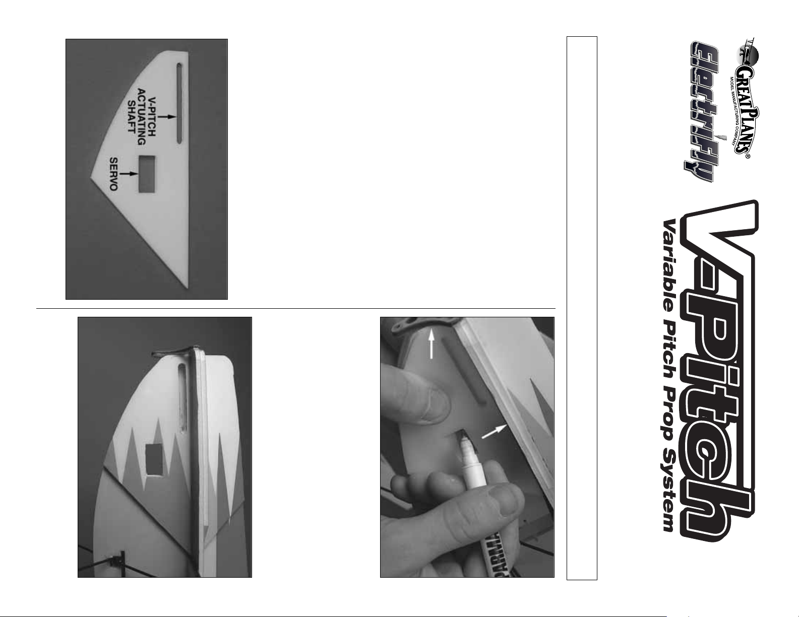
❏ 1.Locate the template f or marking the servo location and
the exit slot for the V-Pitch actuating shaft.
❏ 2. Place the template directly over the bottom fuselage
doubler that is required for the Firewall-Mounted installation.
Trace the template with a fine marker or pen accordingly.Only
trace the template on one side of the plane.
❏ 3. With a sharp hobby knife, cut the servo slot completely
through both sides of the fuselage as shown. Cut the slot for
the servo actuating shaft only on the side you traced as shown.
™
™
These installation instructions for the V-Pitch Variable Pitch Prop System are designed
specifically for use with all Great Planes FlatOut
™
models. Please follow the “Firewall-Mounted
Motor System” instructions in your FlatOut manual before proceeding any further.
Additional items you will need to upgrade your FlatOut with the V-Pitch system are: One 17 oz/in micro servo, a
brushless ESC with governor (ElectriFly’s BL-12, GPMM2075) and a 5-channel micro receiver.
Page 2
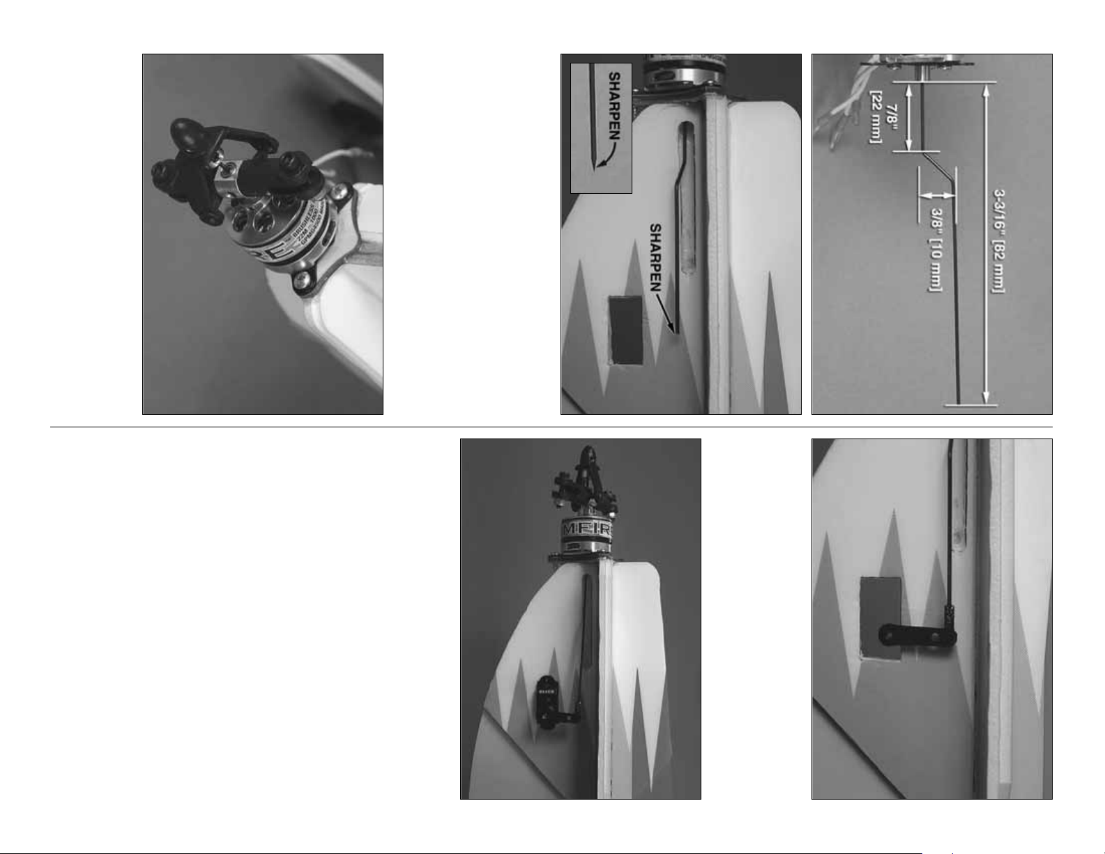
❏ 5. Install the V-Pitch and Rimfire motor onto the plywood
firewall using (3) #4 x 3/8" wood screws (not included).Make
sure the wire exits the slot correctly before tightening the
screws. Apply a drop of foam safe CA to the screws to
ensure they will not back out.
take a sanding bar or a piece of sandpaper and sharpen the
end of the shaft before you install the motor.
❏ 4.Cut the shaft to length as shown above , but be sure that
the blade holders are completely neutral (not pitching forw ard
or backward) when doing this step. Also, bend a slight angle
in the shaft to allow for it to exit the fuselage as shown.Next,
GPMG4490 ......Replacement Blades (2)
GPMG4491 ......Optional Carbon Fiber Blades (2)
GPMG4492 ......Replacement Shaft w/2 Ball Bearings
GPMG4493 ......Spinner/Collar
GPMG4494 ......Screw and Nut Set
GPMG4495 ......Blade Holder w/Ball Bearings
GPMG4496 ......Blade Holder Hub
V-PITCH REPLACEMENT PARTS:
For models other than the Great Planes FlatOuts,
similar mounting methods might apply to your model.
Refer to your model manufacturer for details.
The installation is now complete. Please precede with
the radio set-up instructions on the next page before
you attempt to fly the V-Pitch unit.
❏ 7. Install your servo into the slot as shown with a few
drops of foam safe CA.
❏ 6. Locate one servo arm and a z-bend from your FlatOut
parts tree. Clip the z-bend through the servo arm. Next,
press the shaft into the z-bend as shown. After you have
firmly pressed the shaft into the z-bend, apply a drop of
foam safe CA to keep the shaft from slipping out.
Page 3

Radio Set-Up for V-Pitch
1.When setting up your V-Pitch unit in your radio, be sure to
select the radio’s helicopter prog ram.This will allow y ou to
use pitch and throttle curves.
2. All of your channels will be as follows when using a
Futaba radio:
3. Be sure to set an “idle-up”and a “normal” flight mode in the
radio that can be changed with a switch that you prefer.
This will allow you to disable the V-Pitch with a switch.
“Normal” Mode: Acts just like any other conventional
fixed pitch aircraft.
“Idle-Up” Mode: Allows you to reverse the thrust of the
propeller. When you have your throttle stick in the center
position (0% throttle) you will not have any pitch. As you
push the stick forward (100% throttle) y ou get positiv e pitch
which allows the airplane to move forward. When you pull
the throttle stick back (–100% throttle) it applies negative
pitch to the blades and allows the plane to go in reverse.
4. Before you go any further, unplug all 3 motor wires from
the ESC so you can adjust the ATV (end point) on the
pitch channel in the radio.Set the pitch ATV to maximum
travel for positive and negative pitch.
5. Please see the illustrations for setting up your r adio’ s pitch
and throttle curves when using your V-Pitch with and
without governor mode. Keep in mind that these are just
starting points. You will need to fine tune each point per
your airplane and flying preferences.
• Channel 1: Aileron
• Channel 2: Elevator
• Channel 3:ESC/Throttle
• Channel 4: Rudder
• Channel 5: Pitch
0%
10%
20%
30%
40%
50%
60%
70%
80%
90%
100%
Low Throttle Stick
0%
10%
20%
Negative Pitch
Zero Pitch
30%
40%
50%
60%
70%
Zero Pitch
80%
Throttle (Idle Up) Pitch (Idle Up)
Full Throttle Stick
90%
100%
Low Throttle Stick
Negative Pitch
Zero Pitch
Throttle (Normal) Pitch (Normal)
With Governor Mode Set in the ESC:
Full Throttle Stick
0%
10%
20%
30%
40%
50%
60%
70%
80%
90%
Positive Pitch
100%
0%
10%
20%
30%
40%
50%
60%
70%
80%
90%
Positive Pitch
100%
Page 4

For replacement items or support on this or any other ElectriFly item, please contact:
Low Throttle Stick
Throttle (Idle Up) Pitch (Idle Up)
Low Throttle Stick
Throttle (Normal) Pitch (Normal)
Without Governor Mode Set in the ESC:
www.hobbyservices.com
217-398-0007
Printed in China
productsupport@greatplanes.com
217-398-8970
0%
10%
20%
30%
Low Throttle Stick
Zero Pitch
Full Throttle Stick
40%
50%
60%
70%
80%
90%
100%
0%
10%
20%
30%
40%
50%
60%
70%
80%
90%
Full Throttle Stick
100%
Negative Pitch
Zero Pitch
Full Throttle Stick
Positive Pitch
GPMZ0326 for GPMG4501Entire Contents © Copyright 2006
0%
10%
20%
30%
40%
50%
60%
70%
80%
90%
100%
0%
20%
30%
40%
50%
60%
70%
80%
90%
10%
100%
 Loading...