

Page 1
Great Planes® Power Pod
™
Assembly Instructions
Congratulations on the purchase of the Great Planes Power
Pod. This unit is designed to be used with either an electric
motor or an .049 size glow engine. It may be mounted to your
airplane using one of three different methods.
Firewall
Aft Upright
Front Upright
Base
w/Tabs
1. Spar mounted (GP Spirit™ and other 2-piece wings).
2. Install with bolts (for permanent installation).
Firewall
Supports
Servo Tray
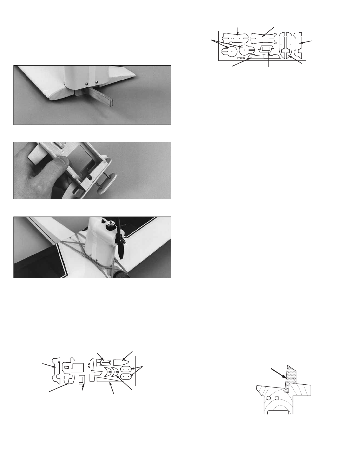
Die-cut sheet PPOD02
Base
Parts Included:
Part# Qty. Description
PPOD01 1 Die-cut Plywood Sheet 1
PPOD02 1 Die-cut Plywood Sheet 2
PPOD03 1 ABS Shroud - Front
PPOD04 1 ABS Shroud - Rear
SCRW043 4 #4 X 3/8" Screws
PPODD01 2 1/2" X 12" White Decal Strips
MOTOR-A 1 Motor Set (Electric Version Only)
SCRW104 4 4-40 X 1-1/4" Screw
NUTS001 4 4-40 Blind Nuts
NYLON146 2 Nylon Tie Straps
WSHR005 4 #4 Washers
VLCRSH03 1 3/4" x 3-1/2" Hook & Loop
Tools Required:
❑
1oz. Thin CA (GPMR6002)
❑ CA Accelerator (GPMR6035)
❑ Hobby Knife with #11 blade
❑ DuraTrax
(DTXR1150)
®
curved scissors for trimming shroud (optional)
❑ Sandpaper
3. Mount with rubber bands (universal/removable).
Please inspect all parts carefully before starting to build. If any
parts are missing, broken, or defective, or if you have any
questions about building the Power Pod, please call us at
(217) 398-8970.
Aft Rib
Forward Rib
Nut
Plates
Motor
Supports
Base
w/Tabs
Main Frame
Side Brace
Fuse
Holder
Die-cut sheet PPOD01
Gluing Technique For Plywood:
For best results when gluing plywood to plywood, first spray the
joint with CA accelerator. Wait about five seconds or enough
time
for the accelerator to evaporate. Then, glue the joint with
thin CA.
Assembly:
Before beginning assembly, choose the mounting method that
best suits your application. Follow the instructions accordingly.
FOR ELECTRIC ONLY!
Remove the shaded area.
❑ 1. If you are planning to use this pod with the electric motor,
complete the cut on the main frame as shown above.
Page 2
Remove
this area
❑ 2. If you are building either the bolt-on or rubber band
version, cut off the bottom of the frame as shown.
❑ 3. Glue the front and rear uprights to the main frame.
❑ 6. Attach the side braces to the uprights and base.
❑ 7. If using an electric motor, glue the two motor supports
together and then attach them to the main frame. Glue a small
strip of sandpaper to the supports and the front upright. This will
help keep the motor in position.
❑ 8. Install the electric motor into the power pod using two
nylon straps (see photo below).
Drill 1/8"
holes at
the marks
❑ 4. If you intend to use the bolt-on method, drill four 1/8" holes
at the punch marks on the base halves.
❑ 5. Glue the base halves to the main frame. If you are using the
rubber band version, use the set of bases that has the tabs.
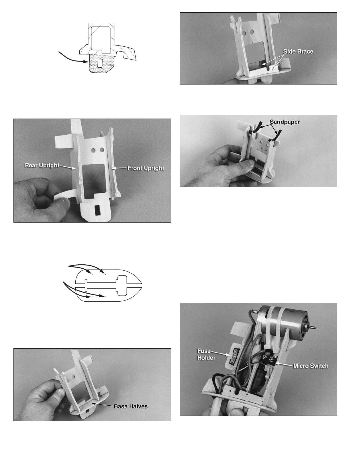
❑ 9. Using two small screws (servo screws work great), attach
the micro switch to the main frame, as shown, in the following
photo. Route the fuse to the back of the pod and secure it in
place using the plywood fuse holder glued to the upright. Attach
the toggle switch to the opposite side brace.
❑ 10. Install a micro servo in the plywood servo tray and glue
into the main frame. Set up your radio system so the servo will
actuate the micro switch when the transmitter is at full throttle.
2 3
Page 3

❑ 11. Attach the ON/OFF switch to the frame.
edges will be trimmed off later. Cut a circle for the toggle switch
and the engine head (if needed). If you use the bases that have
the tabs for rubber bands, trim the shroud around them.
❑ 15. When satisfied with the fit, drill 1/16" holes through the
shroud and into the side braces. Attach the shroud using four
#4 x 3/8" screws.
❑ 16. Use the white decal strips to cover the seam between the
edges of the shroud halves. Start each piece of tape at the top
of the shroud and work towards the bottom. Cut off any excess.
❑ 12. If using an .049 glow engine, glue the two firewall
supports to the main frame. Glue the firewall assembly together
and then to the main frame. Make sure the firewall points are
square to the frame.
❑ 13. Center the engine onto the firewall so the engine head is
straight up. Use 2-56 bolts with locknuts (not included) to secure
the engine.
❑ 17. Trim off the bottom edge of the shroud so it is even with
the bottom of the base.
Mounting the Power Pod to your Model:
Method A:
Mounting on the Great Planes Spirit with two-piece wing.
❑ 14. Trim the mating edges, and test fit the shroud halves
together. The edges should meet with minimal gaps. The bottom
❑ 1. Position the Power Pod onto the wing root and insert the
wing joiner. Glue the plywood rib spacers to the root of one of
the wing panels. If needed, carefully trim away balsa to allow
additional clearance for the servo and battery wires.
Page 4

❑ 2. Reposition the servos and pushrods if needed to allow a
place for the motor battery. Try to locate the battery so it is
centered as close as possible to the center of gravity. Secure
the battery in place with hook and loop strips (GPMQ4480).
❑ 3. IMPORTANT!! Rebalance your plane according to the
airplane manufacturer’s instructions.
Method C:
Universal mounting using rubber bands.
Method B:
Universal mounting using the “Bolt-On” system.
Position the
4-40 x 1-1/4" Bolts
4-40 Blind nuts
wing spars
between
the bolts.
❑ 1. With the shroud removed, position the Power Pod onto the
wing so it is centered over the wing joiner.
❑ 2. Mark the hole locations through the base.
❑
3. If needed, cut or drill a hole for the servo and battery
wires.
❑ 1. Cut the piece of hook and loop lengthwise into two strips.
Attach the strips to the bottom of the pod.
❑ 2. Position the Power Pod onto the wing so it is centered over
the center of gravity. Install the mating hook and loop material
on the wing so it lines up properly.
❑ 3. Reposition the servos and pushrods if needed to allow a
place for the motor battery. Try to locate the battery so it is
centered as close as possible to the center of gravity. Secure
the battery in place with hook and loop strips.
❑
4. Attach the wing to the fuselage with rubber bands. Position
the rubber bands over the tabs on the pod. Crisscross two on
each side for extra security.
❑ 5. IMPORTANT!! Rebalance your plane according to the
airplane manufacturer’s instructions.
Flying with the Great Planes Power Pod:
With the Power Pod running, hand launch the glider with a
straight and level toss into the wind. The glider will climb almost
immediately. When you get high enough, turn off the motor (if
servo controlled) and soar around the sky. It is not uncommon
to get five or six climb-outs using a 6-cell SCR type battery
pack. When you notice a significant power drop, set up to land.
When flying with a glow engine, find an assistant to aid in
starting and launching. Climb and soar until the engine runs out
of fuel.
❑ 4. Drill 1/8" holes all the way through the wing at the marks.
❑ 5. Drill 5/32" holes at the punch marks on the two nut plates
and install the four blind nuts in the holes.
❑ 6. Position the pod in place and insert the 4-40 screws with
washers into the pod and through the wing. Tighten the screws
into the nut plates.
❑ 7. Reposition the servos and pushrods if needed to allow a
place for the motor battery. Try to locate the battery so it is
centered as close as possible to the center of gravity. Secure
the battery in place with hook and loop strips.
❑ 8. IMPORTANT!! Rebalance your plane according to the
airplane manufacturer’s instructions.
Good Luck and Happy Flying!
Entire Contents © Copyright 2009 Printed In USAPPODP01 v1.1
 Loading...