

Page 1
CONGRATULATIONS!
Thank you for choosing the Top Speed Tunnel Hull.This boat has been designed for the intermediate
to advanced boater looking for an easy to assemble, yet high performance tunnel hull. The assembly
is quick and easy, with no special tools or modeling skills required. The Top Speed is a fast, high
performance boat that can be adjusted to differing water conditions to perform at its peak potential.
Please read through this instruction manual in its entirety before beginning assembly. It contains
important instructions and war nings concer ning the assembly and use of this model.
Warning! THIS MODEL IS NOT A TOY!
Assembly and operation of this boat must be done by or under the direct supervision of a responsible
adult. If not handled correctly, this model is capable of inflicting serious bodily harm. It is your responsibility
and yours alone to assemble this boat correctly, properly install all R/C components and test and operate it
in a safe and responsible manner.
GPMZ0261 FOR KITS GPMB1050/1055Entire Contents © Copyright 1999
INSTRUCTION
MANUAL
TM
Page 2
PARTS IDENTIFICATION . . . . . . . . . . . . . . . . . . . . . . . 2
SAFETY WARNINGS . . . . . . . . . . . . . . . . . . . . . . . . . . 3
PRECAUTIONS. . . . . . . . . . . . . . . . . . . . . . . . . . . . . . . 3
ADDITIONAL ITEMS REQUIRED . . . . . . . . . . . . . . . . . 3
TOOLS REQUIRED. . . . . . . . . . . . . . . . . . . . . . . . . . . . 3
ASSEMBLY. . . . . . . . . . . . . . . . . . . . . . . . . . . . . . . . . . 4
Assemble the test stand. . . . . . . . . . . . . . . . . . . . . . . 4
Install the radio system . . . . . . . . . . . . . . . . . . . . . . . 4
Prepare the hull. . . . . . . . . . . . . . . . . . . . . . . . . . . . . 6
Prepare the upper tunnel . . . . . . . . . . . . . . . . . . . . . . 7
Engine installation . . . . . . . . . . . . . . . . . . . . . . . . . . . 8
Fuel tank installation . . . . . . . . . . . . . . . . . . . . . . . . . 8
Linkage installation . . . . . . . . . . . . . . . . . . . . . . . . . . 8
Radio box cover installation . . . . . . . . . . . . . . . . . . . 11
FINISHING . . . . . . . . . . . . . . . . . . . . . . . . . . . . . . . . . 12
Apply the decals and trim . . . . . . . . . . . . . . . . . . . . . 12
FINAL PREPARATIONS . . . . . . . . . . . . . . . . . . . . . . . 12
Balancing your model. . . . . . . . . . . . . . . . . . . . . . . . 12
Operation check. . . . . . . . . . . . . . . . . . . . . . . . . . . . 13
Range check your radio. . . . . . . . . . . . . . . . . . . . . . 13
Engine safety precautions . . . . . . . . . . . . . . . . . . . . 13
Operating procedures . . . . . . . . . . . . . . . . . . . . . . . 13
Operational trimming . . . . . . . . . . . . . . . . . . . . . . . . 14
Maintenance . . . . . . . . . . . . . . . . . . . . . . . . . . . . . . 14
RACING FUN . . . . . . . . . . . . . . . . . . . . . . . . . . . . . . . 15
PARTS ORDERING INFORMATION . . . . . . . back cover
2
TABLE OF CONTENTS
PARTS IDENTIFICATION
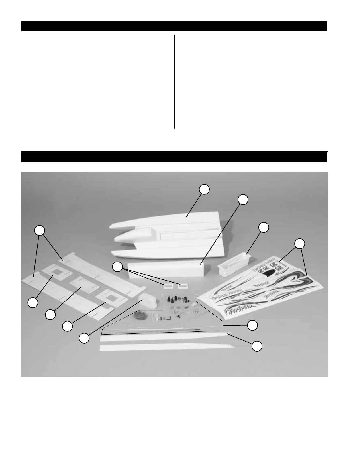
1. Hull
2. Radio Box
3. Upper Tunnel
4. Servo Tray
5. Stand Sides
6. Stand Cross Member Large
7. Stand Cross Member Small
8. Fuel Tank
9. Decals
10. Hardware
11. Speed Str ips
10
8
3
5
9
11
4
6
7
6
1
2
Page 3
Keep in mind that it is impossible f or us to guide you specifically
as to every possible matter that might come up as you
assemble the model. The fun and challenge is to tackle the
problem, using the instructions and photos for resources, as
well as the assistance and advice of fellow modelers and your
local hobby dealer.
The instructions are the basic guide to assembly. Do not alter
or modify the model. Follow the step-by-step instructions
carefully. Read and obey cautions, warnings and directions on
such items as glues, paints and other materials. These are
often TOXIC to the human body in terms of breathing and/or
touch. Be especially cautious of cyanoacrylate glues (also
known as CA glues) that dry almost instantly and bond with
great strength. They require special care since they can be
extremely dangerous if they get into the e yes or on the human
skin. Keep small children and pets away from all building and
finishing materials. Keep your building area safe and clean.
We’ll try to make your boating experience as enjoyable and
“snag-free”as possible.If you find that y our kit has any missing
or defective parts, or if you have any questions about building
or operating this model, please call us at (217) 398-8970 and
we’ll be glad to help. If you have problems with or questions
about any accessory items not included in the parts list
(batteries, chargers, radios, fuel, starting equipment, etc.)
please contact the hobby supplier that sold you those items.
❏ 2-channel radio system with two (2) servos*.The radio
system you use must be on a “surface only”
frequency. Watertight servos are recommended, but
not required.
*NOTE: It is recommended one of the servos have
at least 65 Oz. In. of torque for use as the steering
servo.
❏ Waterproof bag for receiver, such as the Kyosho
TR-12 waterproof rubber bag (KYOB6055)
❏ Small bottle of CA* glue (GPMR6007)
❏ Rubbing alcohol
❏ Clear tape
❏ Pro thread locking compound (GPMR6060)
❏ Shoe-Goo (DTXC2460)
❏ 6-Minute epoxy (GPMR6045)
❏ Weights (GPMQ4485)
❏ Mixing sticks (GPMR8055)
*NOTE: In several places, the instructions call for the use of
“CA glue.” The glue used in the Top Speed instruction
manual is GREAT PLANES PRO®CA+ MEDIUM
(GPMR6007) and is available from y our local hobb y shop).
❏ Electric or hand drill
❏ Drill Bits:1/16" [1.6mm], 5/64" [2mm], 1/8" [ 3mm],
5/32" [ 4mm], 3/16" [ 4.8mm], 1/4" [ 6mm], 7/16" [11mm]
❏ Small screwdrivers (regular and phillips)
❏ Pliers
❏ Sandpaper (180, 320 and 400 grit)
❏ Flat file
❏ Hobby knife
❏ Scissors
❏ Masking tape
❏ Clear tape
❏ Paper towels
TOOLS REQUIRED
ADDITIONAL ITEMS REQUIRED
PRECAUTIONS
WARNING!
This boat is controlled by radio control, which is subject
to possible interference from other R/C transmitters,
paging systems and many other sources of RF or
electrical noise.When operating this boat, allow a “safety
margin” to avoid an accident in the event you experience
a brief loss of control.Before turning your radio on, make
sure no one else in the area is operating a radio on the
same frequency (channel).
WARNING!
Because of the speed and mass of this boat, it is
capable of inflicting property damage and severe
personal injury if a collision occurs. Never run this boat
in the presence of swimmers or where the possibility
of collision with people or property exists.
WARNING!
The engine is very powerful and spins the propeller
with great torque. Read the instructions manual
included with you engine for proper operating
procedures and safety precautions.
SAFETY W ARNINGS
3
Page 4
NOTE: Notice that the outboard engine protr udes from the
bottom of the hull and is very susceptible to damage.
Therefore, you m ust use care to av oid setting the boat do wn
on any surface.In the following steps you will assemble the
“test stand.” Always keep your boat on this stand when it is
not in the water.
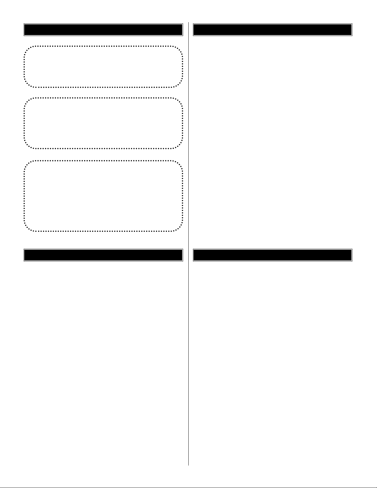
❏ 1. From the two die-cut plywood sheets, remove the
Stand Sides and Cross Members (Large).Save the Servo
Trays from the center of the cross members (L) for use later
in the manual.
❏ 2. From the remaining die-cut plywood sheet, remove the
Cross Member (Small).
❏ 3. Sand the outer edges of all the par ts to remove any
sharps corners.
❏ 4. Slide the two cross members (L) onto the sides as
shown in the photo. Slide the cross member (S) onto the
front of the sides (there is a slight upward curve at the front).
❏ 5. Apply a few drops of medium CA glue to the joints
where the cross members meet the sides. The glue will
penetrate the wood and form a bond within a few minutes.
❏ 6. Once the CA has fully cured, it is suggested to apply a
coat of clear sealer onto the stand. Top Flite®LustreKote
™
Clear (TOPR7200) works extremely well for this purpose.
Applying a coat of clear will prevent water and fuel from
entering the wood, which will weaken the stand prematurely.
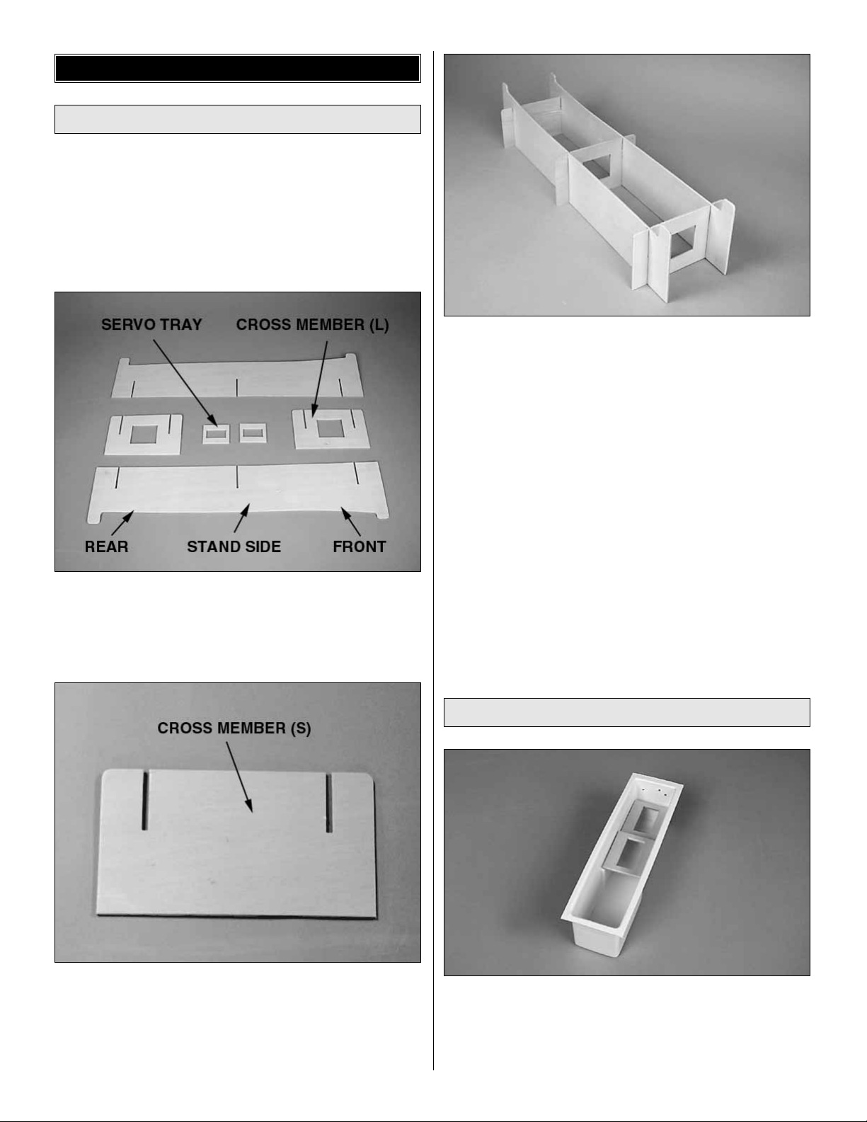
❏ 1. Sand the inside and outside edges of the die-cut ply
servo trays using 320-grit sandpaper.Test fit the servo trays
in the radio box, sanding the edges of the trays as
necessary for a good fit.The servo trays rest on the ledges
molded into the Radio Box.
Install the Radio System
Assemble the Test Stand
ASSEMBLY
4
Page 5
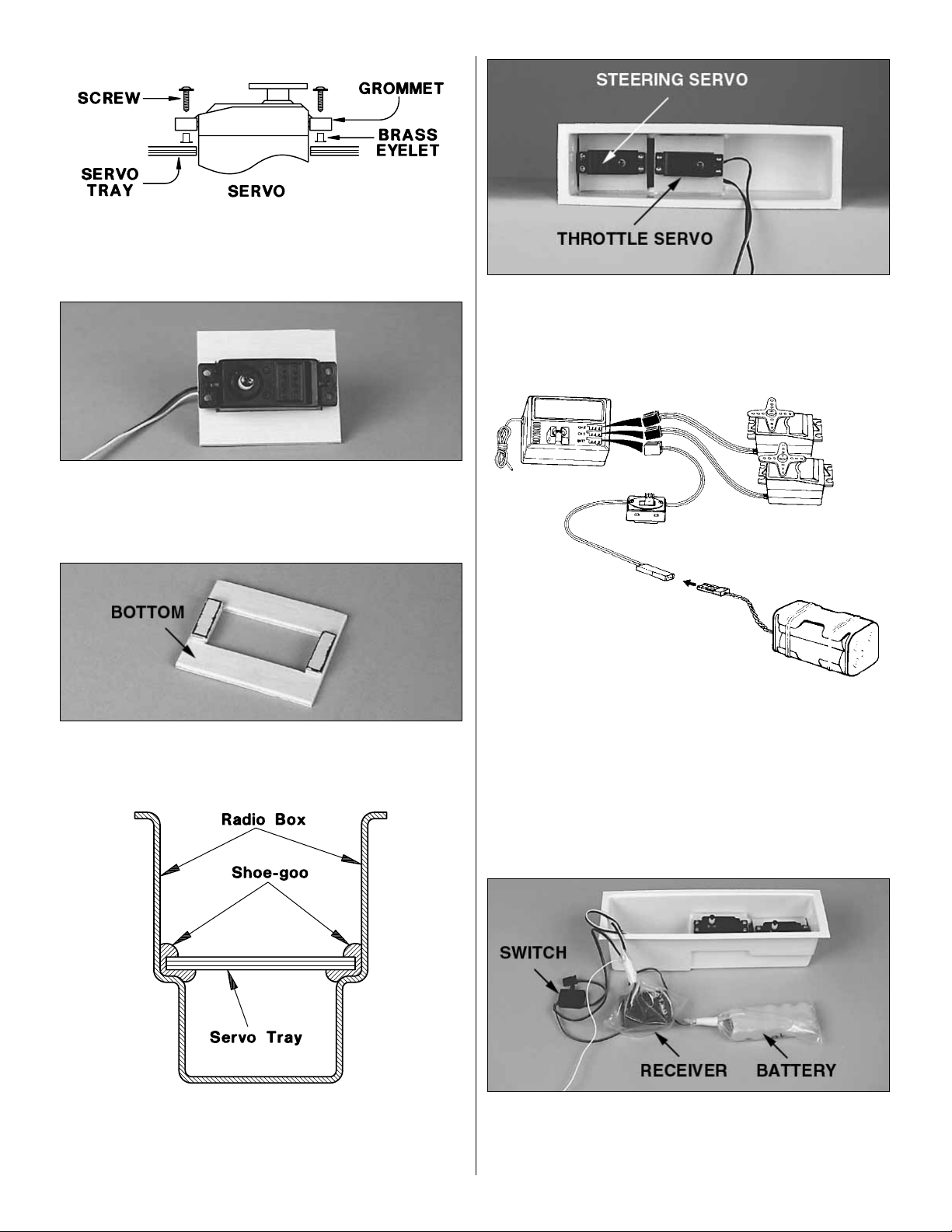
❏ 2. Install the r ubber grommets and brass eyelets in the
servos using the provided sketch.Do not attach the servo to
the tray yet.
❏ 3.T est fit your servos into the openings in the servo trays.
If the openings are too small, enlarge the openings with file
or 180-grit sandpaper until there is a 1/32" [.8mm] gap
around the servo.
❏ 4. Cut four 1/4" x 3/4" servo tray doublers using leftover
plywood from the die-cut sheets.Glue the doublers onto the
servo trays using Medium CA.
❏ 5.Glue the servo trays into the r adio box using Shoe-goo.
Use enough Shoe-goo so it oozes out and slightly onto the
top of the servo tray. The trays are installed so the doubler
is on the bottom of the tray.
❏ 6. Note the direction of the servo output shafts shown in the
photo.While holding the servos in place, mark the locations for
the servo mounting screws onto the tray. Remove the servos
and drill 1/16" [1.6mm] pilot holes through each mark. Mount
the servos with the screws provided with the servos.
❏ 7. Read the instructions included with your radio system
and plug together the receiver, servos, on/off switch and
receiver battery. If your system does not come with a NiCd
receiver battery, install batteries in the battery holder
supplied with your radio system. Switch on the transmitter
and receiver (in that order) and check the operation of your
radio system. Center the trims on the transmitter. Switch off
the receiver and transmitter (in that order) when finished.
❏ 8.Enclose your receiver and receiver battery in waterproof
plastic bags of rubber balloons (the Kyosho TR-12 W aterproof
Rubber Bag (KYOB6055) is an excellent choice). Close the
end of the bag where the wires exit using a twist tie or tape.
5
Page 6

❏ 9. Place a wad of paper towels in the bottom of the radio
box (to absorb any moisture that may enter), then position
the receiver battery and receiver into the radio box in the
front of the servos.
❏ 10. Remove the switch plate from the receiver switch.
Attach the switch to the Switch Mounting Plate using the
two screws that were provided with the switch.
❏ 11. Position the switch assembly in the radio box.
Depending on your choice of radio, the switch may mount
differently than shown. Approximate the location of where
the switch will attach and drill a hole using a 3/16" [4.8mm]
drill bit. Secure the switch using the Switch Retainer.
❏ 12. Place the Switch Actuator onto the switch with the
hole in the actuator facing towards the radio box side. Slide
the Switch Actuator Lever into the hole in the switch
retainer and thread the lever into the actuator.
Note: Inspect the joint between the upper and lower hull. If
there are any areas that are not securely glued, use
medium CA to glue them together. If there are any large
gaps where water could enter the hull, use Shoe-goo to fill
these gaps.
❏ 1.Locate the four 7/8" x 1/4" x 1/4" [22mm x 6mm x 6mm]
Hardwood Blocks. Use 6-minute epoxy to glue the blocks
in the locations shown in the photo.
Prepare the Hull
6
Page 7

❏ 2. Use a 5/64" [2mm] drill bit to dr ill holes in the center of
the hardwood blocks. Use caution not to drill through the
bottom of the hull.Also, there are two indentations in the hull
towards the transom. Drill these locations using a 5/64"
[2mm] drill bit.
❏ 3. Thread the Retaining Hooks into the blocks and hull
as shown in the photo above. Screw them in until the
threads are barely visible.
❏ 4.Trim the front of the hull 1/4" [6mm] inside the outer edge.
This is where the weight to balance the hull will be placed.
❏ 1. Locate the Upper T unnel.Trim the upper tunnel along
the lines scribed onto the tunnel.
❏ 2. Use a 1/8" [3mm] drill bit to drill four holes into the
upper tunnel at the indentations. Use a 1/4" [6mm] drill to
drill the location for the antenna exit.
❏ 3.Position the upper tunnel onto the hull.The angled end
of the tunnel faces the bow, or front, of the boat. Hold the
tunnel in position and mark the locations for the tunnel hold
down screws through the 1/8" [3mm] holes in the tunnel.
❏ 4. Use a 5/64" [2mm] drill bit to drill the four locations for
the tunnel hold down screws.
Prepare the Upper Tunnel
7
Page 8

❏ 1. Prepare your engine for installation using the instructions
provided with the engine.
Note: It may be necessary to purchase an engine mount for
your particular engine. The hull has been predr illed to use
either the O.S..21 XM. or the Du-Bro 3.5cc engine mount.
❏ 2. Attach your engine to the transom using four #8 x 5/8"
Sheet Metal Screws and four #8 Washers. The washers
are placed between the hull and engine mount, two on each
of the lower screws.This is done to accommodate the seam
where the top and bottom hull are joined.
❏ 1. Assemble the Fuel Tankusing the instructions included
with the tank. Use the 90-degree tube when assembling the
fuel tank.
❏ 2. Position the fuel tank as shown in the photo. Use one
Rubber Band to secure the position of the tank. Attach the
rubber band to one of the hooks.Stretch the rubber band to
the other hook, then attach the end to the starting hook.
❏ 1.Use a 7/16" [11mm] drill bit to enlarge the holes for the
pushrod seal mounts.
❏ 2. Press the Pushrod Seal Mounts into the holes from
the outside of the radio box. Place two or three drops of
medium CA inside the radio box to secure the mounts to the
radio box.
Linkage Installation
Fuel Tank Installation
Engine Installation
8
Page 9

❏ 3. Slide the Pushrod Seals onto the mounts. Use
scissors to trim the end of the seal 1/32" [.8mm] so the
pushrod can exit. Use the rubber O-Rings to secure the
seals onto the mounts.
❏ 4. Temporarily install the radio box using two rubber
bands as shown in step 7.
❏ 5.Thread a 2-56 Nut onto each of the 17-1/2" Pushrods.
Add a Silicone Retainer to a Threaded Metal Clevis and
thread the clevis onto the pushrod about 14 turns.
❏ 6. Remove two of the four arms from a cross ser vo arm.
Switch your radio system on and center the steering trim.
(See your radio manual for details.) Install the servo arm so
it is 90-degrees to the centerline of the servo. Switch your
radio system off and proceed to the next step.
❏ 7.Slide a pushrod through one of the pushrod seals in the
radio box.Attach the clevis to the steering arm of the engine.
❏ 8. Position the engine so it is 90-degrees to the transom.
Enlarge the outer most hole in the servo arm using a 5/64"
[2mm] drill bit. Mark one of the pushrods where it crosses
the servo arm. (Make sure the radio box is fully seated
against the hull before marking the pushrod.)
❏ 9. Make a 90-degree bend in the pushrod on your mark,
then cut off the excess wire 3/8" [9.5mm] above the bend.
Insert the bent wire into the servo arm, then secure the
linkage using a Nylon FasLink®as shown in the sketch.
Bend the pushrod if necessary to provide clearance around
the fuel tank.
❏ 10.Locate the 24" [610mm] Pushrod T ube and cut it to a
length of 11-1/2" [293mm]. Roughen the outside of the tube
using 180-grit sandpaper.Slide the tube 2-1/2" [64mm] into
the remaining hole in the radio box as shown.Use medium
CA to glue the tube to the radio box.
9
GP
Page 10

❏ 11. Attach the pushrod tube to the pushrod mount on your
particular engine. It is necessary to have the tube bend as
shown. This will allow for full movement for steering and
reduce the amount of throttle change during steering.
❏ 12. Locate the 24" [610mm] braided pushrod cable and
the solder clevis. Use the following sequence to solder the
clevis to the braided pushrod cable:
A. Lightly sand the pushrod cable and clean it with
alcohol.
B. Inser t the pushrod cable into the non-threaded clevis.
The wire should protrude 1/16" [1.6mm] into the fork
of the clevis.
C. Apply a small amount of solder ing flux to the joint.
D.Apply heat evenly to the pushrod cable and the clevis
and then touch the solder to the joint and allow it to flow.
E. Allow the pushrod and clevis to cool before continuing.
❏ 13.Install a brass Screw-lock Connector with the 4-40 x
1/8" Cap Screw on the throttle arm. Snap the Nylon
Retainer onto the screw-lock connector post on the
opposite side of the throttle arm.
❏ 14. Slide a silicone clevis retainer onto the clevis.Slide the
cable into the pushrod housing, starting from inside the
radio box. As the cable exits the tube, guide it through the
pushrod connector on the throttle arm.
❏ 15.With the radio switched on, install the servo arm onto
the throttle servo as shown in the photo.Manually close the
throttle on the carburetor completely. Tighten the cap screw
on the screw-lock pushrod connector. Check the throttle
operation with the radio and make adjustments to the
linkages as necessary for smooth operation. Use the
appropriate holes in the throttle servo arm to provide the
correct amount of throttle movement and to prevent the
servo from binding at its end points.
❏ 16.Once the throttle has been adjusted, slide the silicone
clevis retainer in position. Cut a mixing stick to fit inside the
radio box as shown. Use medium CA to glue the stick in
position. Glue the throttle tube to the stick, being careful not
to get any glue inside the pushrod tube.
10
Page 11

❏ 1.Temporarily tape the Radio Box Cover to the radio box.
❏ 2.Measure and record the position of the switch.Transfer
this measurement onto the upper tunnel and drill a 3/16"
[4.8mm] hole at the location.Use a hobby knife to “fine tune”
the location of the hole if necessary.
❏ 3.Place the tunnel in position.Using a pen or leftover from
the steering pushrod, mark the location of the antenna exit
through the hole in the upper tunnel onto the radio box cover.
❏ 4. Remove the radio box cover and use a 5/32" [4mm] drill
bit to drill a hole for the antenna in the radio box cover.
❏ 5. Sand the end of the Antenna Tube to a slight taper
(this will permit you to thread the hex nut on).
❏ 6. Grasp the antenna tube firmly and thread one of the
6-32 Hex Nuts 1/4" [6mm] onto the tube with a pliers. HINT:
If you find it difficult to turn the nut, try holding the tube with
another pliers, locking the tube in a vise (use light pressure
to avoid crushing the tube), or having someone else hold
the antenna tube with two hands while you turn the nut.
❏ 7.Insert the antenna tube into the hole drilled in the radio
box cover and secure it with another 6-32 hex nut.
❏ 8. Route the receiver antenna through the antenna tube
so approximately 2" of the antenna protrudes out the top of
the tube.Do not cut off any excess antenna length.Wrap
the excess together and place it inside the radio box.
Radio Box Cover Installation
11
Page 12

❏ 9. Install the radio box cover onto the radio bo x using clear
tape. Make sure the tape fully seals the radio box cover so
water does not enter the radio box.
❏ 10. Secure the radio box to the hull using a total of eight
rubber bands.
❏ 11. Attach the fuel lines from the fuel tank to the engine.
(See the instructions that came with your engine for more
details.) Allow enough slack in the lines to allow the engine
to move fully to the right and left without pulling on the lines,
possibly causing them to come off during operation.The fuel
tank is filled using the line connected to the carburetor.
When the tank is full, the excess fuel will come out of the
fuel line connected to the muffler.
❏ 12.Attach the upper tunnel to the hull using four #4 x 1/2"
Sheet Metal Screws and four #4 Washers.
❏ 13. Using 400-grit sandpaper, lightly sand the bottom of
the sponson and one side of the Speed Strip. Use a paper
towel and rubbing alcohol to remove any dirt or oil from the
sponson and speed strip. Position the speed strip so it
slightly overhangs the edges of the sponson. Glue the
speed strip onto the bottom of the sponson using medium
CA. Use the photos on the box for further positioning of the
speed strips.
NOTE: DO NOT reshape the speed strips. They are
designed to slightly overhang the edges of the sponson.
The sharp edge on the speed strip forces the water to
“break free” of the sponsor, rather than cling to it during
operation. This reduces the amount of water friction,
allowing the boat to “get up on plane” faster and operate at
a higher speed than without the speed strips. The only
modification to the speed strip would be to lightly sand the
edges to re-sharpen them if your Top Speed encounters
anything that damages the edges of the speed strip.
❏ 1. Using a scissors or a hobby knife, cut out the Decals.
❏ 2. Clean the exterior of your boat thoroughly with warm,
soapy water. Rinse and dr y thoroughly.
❏ 3.Peel off the protective bac king and apply the self-adhesiv e
decals, referring to the photos on the box label.HINT:T o apply
large decals, peel only a small portion of the backing from one
end. Cut off the backing with a scissors. Then, position the
decal carefully. Press down the exposed portion of the decal
and remove the rest of the backing.Working from the attached
end, carefully press down the rest of the decal, working any air
bubbles out as you go.
Note: This section is VERY important and must NOT be
omitted! A model that is not properly balanced will be
unstable and possibly flip over during operation.
❏ 1. The balance point (C.G.) is located 7-1/2" [193mm]
forward of the transom.This is the balance point at which your
model should balance for your first runs.After initial trim runs
and when you become more acquainted with your Top
Speed, you may wish to experiment by shifting the balance
forward or backward to change its operating characteristics.
Changing the location of the CG will change the handling
characteristics of your boat.Read the “Operational Trimming”
section at the end of the manual thoroughly to “fine tune” the
performance of your boat.
Balancing Your Model
FINAL PREPARATIONS
Apply the Decals & Trim
FINISHING
12
Page 13

❏ 2. With all the parts of the model installed (ready to run)
and an empty fuel tank, lift the model at the balance point.
If the transom of the boat drops, the model is “tail heavy”
and you must add weight to the front to balance the model.
If the bow drops, it is “nose hea vy”and you must add w eight
to the rear of the boat to balance the model.
Inspect your radio installation and confirm that all the
controls respond correctly to the transmitter inputs. The
engine operation must also be checked by confirming that
the engine idles reliably, transitions smoothly and rapidly to
full power and maintains full power, indefinitely.The engine
must be “broken-in” following the engine manufacturer’s
recommendations. Make sure that all screws remain tight,
that the linkages are secure and that the prop is on tight.
Whenever you go to the pond, check the operational range of
the radio before the first run of the day.First, make sure no one
else is on your frequency (channel).With your transmitter and
receiver on, you should be able to walk at least 100 feet away
from the model and still have control. While you work the
controls, have a helper stand by your model and tell you what
the control surfaces are doing. If the control surfaces are not
always responding correctly, do not run your boat! Find and
correct the problem first. Look for loose servo connections or
corrosion, loose bolts that may cause vibration, a defective
on/off switch, low battery voltage or a def ective receiver battery,
a damaged receiver antenna, or a receiver crystal that may
have been damaged.
Note: Failure to follow these safety precautions may result
in severe injury to yourself and others.
Keep all engine fuel in a safe place, away from high heat,
sparks or flames, as fuel is very flammable. Do not smoke
near the engine or fuel; and remember that the engine
exhaust gives off a great deal of deadly carbon monoxide.
Do not run the engine in a closed room or garage.
Get help from an experienced modeler when learning to
operate engines.
Use safety glasses when starting or running engines. Do
not run the engine in an area of loose gravel or sand; the
propeller may throw such material in your face or eyes.
Keep your face and body as well as all spectators away
from the plane of rotation of the propeller as you start and
run the engine.
Keep these items away from the prop: loose clothing, shirt
sleeves, ties, scarfs, long hair or loose objects such as
pencils or screwdrivers that may fall out of shirt or jacket
pockets into the prop.
Use an electric starter to star t the engine. Do not use your
fingers to flip the flywheel. Make certain the glow plug clip
or connector is secure so that it will not pop off or otherwise
get into the running propeller.
Make sure that any wires from your glow plug clip or star ter
are clear of the propeller before starting the engine.
The engine gets hot! Do not touch it during or right after
operation.Make sure fuel lines are in good condition so fuel
will not leak onto a hot engine, causing a fire.
To stop a glow engine, cut off the fuel supply by closing off
the fuel line or following the engine manufacturer’s
recommendations. Do not use hands, fingers or any other
body part to tr y to stop the engine. Do not throw anything
into the propeller of a running engine.
If you have followed all of the previous instructions and find
everything to be operating properly, your Top Speed should
now be ready to run! Here is the procedure that should be
followed (some of these steps may already be completed):
❏ 1. If your radio system has rechargeable batteries, charge
the transmitter and receiver batteries, according to the radio
manufacturer’s instructions.
❏ 2.Tur n on the transmitter and receiver (in that order).
❏ 3. Check to make sure the throttle and steering are
operating properly. NO TE:Looking at the boat from the rear,
the aft edge of the engine must move to the right when the
transmitter steering wheel/stick is turned right (clockwise).
❏ 4. Ask yourself, “If the boat becomes dead in the water,
will I be able to retrieve it either by waiting for the wind to
blow it in to shore, or by using a retrieval boat?” There is
always a chance of something going wrong and the boat
going “dead”; therefore, you should always have a plan for
retrieval in that event.
Caution: If you go out in a boat to retrieve a model boat, be
sure to wear an approved floatation device. Never swim or
wade in the water to retrieve a model boat!
Operating Procedures
Engine Safety Precautions
Range Check Your Radio
Operation Check
13
Page 14

❏ 5. Start and adjust the engine following the procedures
outlined in the instructions included with your particular engine.
❏ 6. Place the boat in water that is at least 8 inches deep
and free of debris that may tangle or damage the prop.
❏ 7. Advance the throttle and note if the boat has a
tendency to turn right or left. Adjust the steering trim tab on
your transmitter until the boat runs in a straight line when the
wheel/stick is neutralized.
❏ 8. Try some turns to the right and left. First, make big
gentle turn and gradually make tighter turns to see how your
Top Speed handles. If your Top Speed “spins out” or is on
the verge of flipping over in tight turns, you can reduce the
steering movement by making adjustments on your
transmitter (if you have a transmitter that allows this type of
“endpoint adjustment”.) To prevent swamping, avoid making
tight turns in rough water.
❏ 9. Total run time of the Top Speed is approximately 5-6
minutes on a full tank of fuel. It is suggested to use a timer
to time your Top Speed to prevent it from stopping while in
the middle of your pond or lake.
❏ 10. After operating your Top Speed, place it on the stand.
Use paper towels to dry off the hull. Remove the upper
tunnel and check the radio box to see if any water has
entered.If so, remov e the radio box cover and dry the inside
of the box. Check the propeller for weeds or other debris.
Remove any foreign material which may have become
entangled. WARNING: If, during operation, you notice the
boat suddenly slow down or loose power, it probably means
that weeds or other debris have tangled around the
propeller. This could cause excessive overheating of the
engine, therefore, you should immediately bring the boat to
shore, shut off the engine and inspect the engine and
propeller for any foreign matter and remove it.
❏ 11.When you have finished for the day, dry the boat inside
and out and recharge the batteries. Place the boat on its
stand for storage.Periodically (and for long term storage) you
should also remove the radio box cover, wipe it off and clean
out the inside of the radio box. You should also read the
instructions included with your engine for any procedures to
prepare the engine for long term storage.
IMPORTANT NOTE: If, for whatever reason, your boat takes
on a large amount of water, swamps or sinks, causing the
radio equipment to get wet, you must do the following:
Immediately remove all batteries and radio equipment from
the boat. Open the receiver (if water has entered the plastic
bag) and servo cases (if not watertight servos) and dry all
components completely before reassembling. To dry
electrical components, use a paper towel to absorb the water
droplets. Then, use a hair dryer to make sure they are
completely dry. Dry the inside of the radio box and reinstall
the components and check for proper operation before
running the boat in water.
Because the outboard engine can be adjusted in both
vertical positioning and angle, the following trimming guide
will give you a rough overview on how to adjust your Top
Speed to pick up some additional speed:
ENGINE ANGLE
Changing the angle of the engine in relationship to the
transom will change the angle of the hull in relationship to
the water.By rotating the engine so the lower end is farther
away from the tr ansom will lift the front (bo w) of the boat out
of the water. By rotating the engine so the lower end is
closer to the transom will force the bow of the boat into the
water. The angle of the engine should be adjusted so the
sponson rides level when cornering.
CENTER OF GRAVITY
Changing the center of gravity will also alter the angle of the
hull in the water. Adding weight to the bow of the boat
(moving the CG forward) will push the bow into the water.
Adding weight to the transom of the boat (moving the CG
aft) will lift the bow of the boat out of the water. Adjust the
CG as necessary so the boat rides level in the water.
ENGINE HEIGHT
Moving the position of the engine vertically on the transom
will change the vertical positioning of the hull in relationship
to the water. By moving the engine downward on the
transom, the hull will ride higher in the water. Moving the
engine upward will cause the hull to ride lower, or more in
the water.Begin by positioning the engine so the mounting
screws are in the middle of the adjustment range of the
engine. On smooth water, run your Top Speed and obser ve
the positioning of the hull in relationship to the water.The
best positioning of the Top Speed is to have it “skim” slightly
out of the water.
In addition to the items listed under “Top Speed Operating
Procedures,” you should also check the following regularly:
❏ 1. Periodically check to see if the engine is securely
attached to the transom. Because of the amount of force
applied to the hull during operation, it is possible these
screws may loosen.
❏ 2. Periodically check the steering linkages for free
movement. In time, the engine may accumulate debris
between the mount plate and outboard unit. If this happens,
remove the outboard unit (following the manufacturers
instructions) and clean both the mount plate and outboard
unit. Reassemble and check for free movement.
❏ 3. After running in salt water, clean the boat thoroughly
with fresh water. Follow the manufacturers instructions on
cleaning and maintenance for your particular engine.
Maintenance
Operational Trimming
14
Page 15

Although it is very enjoyable to go out alone and “hot dog”
with your Top speed, we think the real fun and excitement is
experienced when you get involved in RACING!
Racing does not have to be an organized and sanctioned
competition to be fun. In fact, small, informal races can be
very exciting without the stress that comes with the more
formal ones.
Following are some suggestions f or setting up a simple race
course for electric boats:
1. Make 2, 3 or 4 simple and inexpensive “marker buoys”
with empty milk jugs, string and heavy objects for anchors,
similar to the above sketch.
2. For “drag racing” place the buoys in a pattern similar to
the above sketch.
3. For “oval racing” place the buoys in a pattern similar to
the above sketch.
NOTE: The above patterns are “about right” for racing
electric boats, and they are not based on any official
standards; therefore, you can set up courses any way you
desire, using your imagination to make the races more
interesting. Usually the smaller courses will provide more
action and excitement.
Races will be more exciting if the boats are closely matched
in performance. Two or three Top speeds in the same race
can be a lot of fun, especially if they are all using battery
packs having the same number of cells. If you must race
boats having large speed differences, try giving the slower
boats a “handicap.” For instance, give the slower boats a
1/2-lap or 10 second head start (more or less, depending on
the speed difference and length of the race).
The length of the race can be determined by a set
number of laps around the buoys (for example , the first boat
to complete 5 laps is the winner); or by time (for example,
whoever is leading at the end of 2 minutes is the winner).
The RBRC Battery
Recycling Seal on the
nickel-cadmium (NiCd)
battery that should be
used in our product,
indicates Hobbico is
voluntarily participating in
an industry program to
collect and recycle these
batteries at the end of
their useful life, when
taken out of service in the United States or Canada. The
RBRC program provides a convenient alternative to placing
used NiCd batteries into the trash or the municipal waste
system, which is illegal in some areas. Please call 1-800822-8837 for information on Ni-Cd battery recycling in your
area. Hobbico's involvement in this program is part of our
commitment to preserving our environment and conserving
our natural resources.
RECYCLING
RACING FUN WITH YOUR TOP SPEED
15
Page 16

GPMQ4103 1 Fuel tank
GPMZ0261 1 Instruction manual
METAL013 2 2-56 Threaded clevis
METAL030 1 Solder clevis
METAL056 1 Quick connector
METAL076 6 Cup hooks
NUTS005 2 2-56 Hex nut
NUTS010 2 6-32 Hex nut
NYLON177 1 Kwik switch 203-B
NYLON178 1 Waterproof pushrod seal
NYLON85C 1 Retainer
NYLON91 2 Faslink pushrod keeper
PLTB012 1 11-3/4" Tube white
PLTB020 1 24" Pushrod tube
PLTB021 3 Clevis retainer
PLTB028 1 Fuel tubing
SCRW004 4 #4x1/2" Sheet metal screw
SCRW054 4 #8x5/8" Truss head sheet metal screw
SCRW100 1 4-40x1/8" Socket head cap screw
TPSD001 1 Radio cover
TPSDD01 1 Decal 1
TPSDD02 1 Decal 2
TPSPDDC01 2 3x30" Speed strip
TPSPDDC02 1 Stand support
TPSPDDC03 2 Stand sides
WIRES11 2 17-1/2" Pushrod treaded one end
WIRES73 1 24" Cable
WSHR005 4 #4 Flat washer
WSHR011 4 #8 Flat washer
PARTS ORDERING INFORMATION
❑
PAYMENT ENCLOSED
SUB-TOTAL
❑
PLEASE SEND C.O.D.
S & H $4.50
❑
VISA
❑
M/C
C.O.D.ADD $5.00
CARD #
2
ND
DAY AIR ADD $10.00
EXP DATE
/
NEXT DAY AIR ADD $20.00
❑
PLEASE SEND CATALOG
IL. RES. ADD 7.25% TAX
TOTAL
NAME __________________________________________
ADDRESS_______________________________________
CITY_________________________ST____ZIP_________
PHONE # ________________________
SEND TO:
Great Planes Model Mfg.
P.O. BOX 788, Urbana, IL 61803
or Phone (217) 398-8970 for C.O.D. orders
We do accept MasterCard and Visa credit cards.
Please print clearly on all orders. Note: Parts and
prices are subject to change without notice.
Printed in USA
CALL OR WRITE FOR CURRENT PRICES
or e-mail productsupport@greatplanes.com
HAND-CRANK FUEL PUMP............................HCAP3015
Uniquely geared for smooth, efficient, long-lasting
operation, this pump delivers 1/4-oz.of glow fuel with every
turn of the handle. It fills or drains with equal ease. The
durable nylon case includes flanges for easy field box
attachment. Fuel tubing is also included.
HOBBICO®TORQMASTER™STARTER........HCAP3200
TorqMasters include easy-press start switch, turned
aluminum starter cone w/grooved silicone insert and 5’input
cord. *TorqMaster 90* starts engines up to .90; *TorqMaster
180*, engines up to 1.8 cu. in.
 Loading...