

Great Planes GPMA1166 User Manual
INSTRUCTION
:
5
[
]
i
2
]
o
z/f
t
2
0
/dm
2
]
]
W
[
136 0
]
s
CIRRUS® is a registered trademark of Cirrus Design Corporation and is in no way affiliated with Hobbico, Inc.
SPECIFICATIONS
SPECIFICATIONS
Wingspan: 50.5 in [1285mm]
Wingspan
Wing Area: 305 in
Wing Area:05
Wing Loading: 19-23 oz/ft
Wing Loading:-23
WARRANTY
WARRANTY
Great Planes® Model Manufacturing Co. guarantees this kit to
be free from defects in both material and workmanship at the
date of purchase. This warranty does not cover any component
parts damaged by use or modification. In no case shall Great
Planes’ liability exceed the original cost of the purchased kit.
Further, Great Planes reserves the right to change or modify this
warranty without notice.
In that Great Planes has no control over the final assembly or
material used for final assembly, no liability shall be assumed nor
accepted for any damage resulting from the use by the user of
the final user-assembled product. By the act of using the
user-assembled product, the user accepts all resulting liability.
If the buyer is not prepared to accept the liability associated
with the use of this product, the buyer is advised to return
0.5 in
2
2
[19.7 dm2]
19.7 dm
2
mm
[58-70 g/dm2]
-7
ength:6 in [915mm
Length: 36 in [915mm]
eight:2.5-3 lb
Weight: 2.5-3 lb [1130-1360 g]
Radio: 4-channel, 4-nano servos
Radio:4-channel, 4-nano servos
this kit immediately in new and unused condition to the
place of purchase.
To make a warranty claim send the defective part or item to
Hobby Services at the address below:
Include a letter stating your name, return shipping address, as
much contact information as possible (daytime telephone
number, fax number, e-mail address), a detailed description of
the problem and a photocopy of the purchase receipt. Upon
receipt of the package the problem will be evaluated as quickly
as possible.
MANUAL
-
g
Hobby Services
3002 N. Apollo Dr. Suite 1
Champaign IL 61822 USA
otor:
Motor: .10 (35-30-1250) Brushless
10 (35-30-1250) Brushles
Outrunner
utrunner
READ THROUGH THIS MANUAL BEFORE STARTING CONSTRUCTION. IT CONTAINS IMPORTANT
INSTRUCTIONS AND WARNINGS CONCERNING THE ASSEMBLY AND USE OF THIS MODEL.
Champaign, Illinois
(217) 398-8970, Ext 5
airsupport@greatplanes.com
© 2010 Hobbico®, Inc. GPMA1166 Mnl
TABLE OF CONTENTS
INTRODUCTION . . . . . . . . . . . . . . . . . . . . . . . . . . . . . . . .2
SAFETY PRECAUTIONS . . . . . . . . . . . . . . . . . . . . . . . . .2
DECISIONS YOU MUST MAKE. . . . . . . . . . . . . . . . . . . . .3
Radio Equipment . . . . . . . . . . . . . . . . . . . . . . . . . . . . .3
Motor Recommendation. . . . . . . . . . . . . . . . . . . . . . . .3
Propeller. . . . . . . . . . . . . . . . . . . . . . . . . . . . . . . . . . . .3
Batteries and Charger . . . . . . . . . . . . . . . . . . . . . . . . .3
Pilot . . . . . . . . . . . . . . . . . . . . . . . . . . . . . . . . . . . . . . .3
ADDITIONAL ITEMS REQUIRED . . . . . . . . . . . . . . . . . . .4
Adhesives and Building Supplies. . . . . . . . . . . . . . . . .4
Optional Supplies and Tools. . . . . . . . . . . . . . . . . . . . .4
Building Stand . . . . . . . . . . . . . . . . . . . . . . . . . . . . . . .4
IMPORTANT BUILDING NOTES. . . . . . . . . . . . . . . . . . . .4
KIT INSPECTION. . . . . . . . . . . . . . . . . . . . . . . . . . . . . . . .5
ORDERING REPLACEMENT PARTS . . . . . . . . . . . . . . . .5
KIT CONTENTS. . . . . . . . . . . . . . . . . . . . . . . . . . . . . . . . .5
BUILDING INSTRUCTIONS . . . . . . . . . . . . . . . . . . . . . . .6
Preparations. . . . . . . . . . . . . . . . . . . . . . . . . . . . . . . . .6
Assemble the Wing Panels . . . . . . . . . . . . . . . . . . . . .6
Install the Tail Section . . . . . . . . . . . . . . . . . . . . . . . . .9
Install the Nose Gear, Motor and ESC. . . . . . . . . . . .12
Finish the Model. . . . . . . . . . . . . . . . . . . . . . . . . . . . .14
APPLY THE DECALS . . . . . . . . . . . . . . . . . . . . . . . . . . .16
GET THE MODEL READY TO FLY . . . . . . . . . . . . . . . . .17
Check the Control Directions . . . . . . . . . . . . . . . . . . .17
Set the Control Throws. . . . . . . . . . . . . . . . . . . . . . . .17
Balance the Model (C.G.). . . . . . . . . . . . . . . . . . . . . .18
Balance the Model Laterally. . . . . . . . . . . . . . . . . . . .19
PREFLIGHT . . . . . . . . . . . . . . . . . . . . . . . . . . . . . . . . . . .19
Identify Your Model . . . . . . . . . . . . . . . . . . . . . . . . . . .19
Charge the Batteries . . . . . . . . . . . . . . . . . . . . . . . . .19
Balance Propellers. . . . . . . . . . . . . . . . . . . . . . . . . . .19
Range Check . . . . . . . . . . . . . . . . . . . . . . . . . . . . . . .19
MOTOR SAFETY PRECAUTIONS . . . . . . . . . . . . . . . . .20
LITHIUM BATTERY HANDLING AND USAGE . . . . . . . .20
AMA SAFETY CODE. . . . . . . . . . . . . . . . . . . . . . . . . . . .20
CHECK LIST . . . . . . . . . . . . . . . . . . . . . . . . . . . . . . . . . . 21
FLYING. . . . . . . . . . . . . . . . . . . . . . . . . . . . . . . . . . . . . . . 21
Takeoff . . . . . . . . . . . . . . . . . . . . . . . . . . . . . . . . . . . .21
Flight . . . . . . . . . . . . . . . . . . . . . . . . . . . . . . . . . . . . .22
Landing . . . . . . . . . . . . . . . . . . . . . . . . . . . . . . . . . . .22
INTRODUCTION
Congratulations on your purchase of the Great Planes
ElectriFly Cirrus SR22 ARF! With only an evening or two of
fi nal assembly, you will be rewarded with a beautiful scale
model that fl ies with inexpensive radio components and can
fi t in the backseat of a car without removing the wings. The
wings can be removed for storage by simply unscrewing the
knurled wing bolts and sliding the panels off of the lightweight
carbon wing tube. Battery changes are a snap with the self-
aligning magnetic hatch. A fi berglass fuselage and canopy
hatch ensure a smooth appearance that looks great in the
pits and in the air. A cockpit interior, which only requires the
addition of a pilot(s) of your choice, fi nishes off the realism.
For the latest technical updates or manual corrections to
the Cirrus SR22 ARF visit the Great Planes web site at
www.greatplanes.com. Open the “Airplanes” link, then
select the Cirrus SR22 ARF. If there is new technical
information or changes to this model a “tech notice” box will
appear in the upper left corner of the page.
AMA
If you are not already a member of the AMA, please join!
The AMA is the governing body of model aviation and
membership provides liability insurance coverage, protects
modelers’ rights and interests and is required to fl y at most
R/C sites.
ACADEMY OF MODEL AERONAUTICS
5151 East Memorial Drive
Muncie, IN 47302-9252
Tele. (800) 435-9262
Fax (765) 741-0057
Or via the Internet at:
www.modelaircraft.org
IMPORTANT!!!
Two of the most important things you can do to preserve the
radio controlled aircraft hobby are to avoid fl ying near fullscale aircraft and avoid fl ying near or over groups of people.
PROTECT YOUR MODEL, YOURSELF
& OTHERS… FOLLOW THESE
IMPORTANT SAFETY PRECAUTIONS
1. Your Cirrus SR22 ARF should not be considered a toy, but
rather a sophisticated, working model that functions very
much like a full-size airplane. Because of its performance
capabilities, the Cirrus SR22, if not assembled and operated
correctly, could possibly cause injury to yourself or spectators
and damage to property.
2. You must assemble the model according to the
instructions. Do not alter or modify the model, as doing so
may result in an unsafe or unfl yable model. In a few cases
the instructions may differ slightly from the photos. In those
instances the written instructions should be considered
as correct.
3. You must take time to build straight, true and strong.
4. You must use an R/C radio system that is in good condition,
a correctly sized motor, and other components as specifi ed
in this instruction manual. All components must be correctly
installed so that the model operates correctly on the ground
and in the air. You must check the operation of the model and
all components before every fl ight.
5. If you are not an experienced pilot or have not fl own
this type of model before, we recommend that you get
the assistance of an experienced pilot in your R/C club for
2

your fi rst fl ights. If you’re not a member of a club, your local
hobby shop has information about clubs in your area whose
membership includes experienced pilots.
6. While this kit has been fl ight tested to exceed normal use,
if the plane will be used for extremely high stress fl ying, such
as racing, or if a motor larger than one in the recommended
range is used, the modeler is responsible for taking steps to
reinforce the high stress points and/or substituting hardware
more suitable for the increased stress.
7. WARNING: The fuselage, wheel pants, and canopy hatch
included in this kit are made of fi berglass, the fi bers of which
may cause eye, skin and respiratory tract irritation. Never
blow into a part to remove fi berglass dust, as the dust will
blow back into your eyes. Always wear safety goggles, a
particle mask and rubber gloves when grinding, drilling and
sanding fi berglass parts. Vacuum the parts and the work
area thoroughly after working with fi berglass parts.
We, as the kit manufacturer, provide you with a top quality,
thoroughly tested kit and instructions, but ultimately the
quality and fl yability of your fi nished model depends
on how you build it; therefore, we cannot in any way
guarantee the performance of your completed model,
and no representations are expressed or implied as to the
performance or safety of your completed model.
Remember: Take your time and follow the instructions to
end up with a well-built model that is straight and true.
Propeller
If you are installing the recommended RimFire brushless
motor, we suggest a 10x7E APC propeller (APCQ4123).
Batteries and Charger
One 1500-3350mAh 11.1V Lithium Polymer battery pack
is recommended. Using a 2200mAh 11.1V LiPo, our SR22
balanced at the recommended C.G. without the need for
additional ballast.
Great Planes ElectriFly LiPo 3S 11.1V 1500mAh 25C
❏
(GPMP0511)
Great Planes ElectriFly LiPo 3S 11.1V 2200mAh 25C
❏
(GPMP0520)
FlightPower® EON-X™ Lite LiPo 3S 11.1V 2500mAh 25C
❏
(FPWP4238)
Great Planes ElectriFly LiPo 3S 11.1V 3350mAh 25C
❏
(GPMP0541)
A cell balancer is required for the LiPo battery packs listed
above:
Great Planes ElectriFly Equinox™ LiPo Cell Balancer 1-5
❏
(GPMM3160)
DECISIONS YOU MUST MAKE
This is a partial list of items required to fi nish the Cirrus SR22
ARF that may require planning or decision making before
starting to build. Order numbers are provided in parentheses.
Radio Equipment
The Cirrus SR22 ARF requires a minimum 4-channel radio
system with four nano servos such as the ElectriFly ES-50
nano servo. In addition, two 12" [305mm] servo extensions
and a dual servo extension are required for the aileron servos.
Great Planes ElectriFly ES50 Nano Servo J (GPMM1210)
❏
Hobbico® Extension 12" [152mm] Futaba J (HCAM2100)
❏
Futaba® Dual Servo Extension 6" J (FUTM4130)
❏
Motor Recommendation
The recommended motor for the Cirrus SR22 ARF is a
RimFire™ .10 (35-30-1250) brushless outrunner motor.
Great Planes RimFire .10 (35-30-1250) Outrunner
❏
Brushless (GPMG4595)
If using the recommended brushless motor, a 35A brushless
ESC is required:
Great Planes Silver Series 35A Brushless ESC 5V/2A
❏
(GPMM1830)
A suitable charger is also required. The Great Planes
PolyCharge4™ is designed for LiPo packs only. However, it
is able to charge four LiPo packs simultaneously. The Great
Planes Triton2™ charger will only charge one pack at a time,
but is capable of charging NiCd, NiMH, LiPo, and Pb acid
batteries. Order numbers for both are provided below:
Great Planes PolyCharge4 DC Only 4 Output LiPo
❏
Charger (GPMM3015) OR
Great Planes ElectriFly Triton2 DC Comp Peak Charger
❏
(GPMM3153)
Pilot
If you wish to use the same pilot that is shown in the building
instructions, purchase Williams Brothers 1/8 Pilot Bust Kit
Sportsman (WBRQ1130). This pilot fi gure requires fi nish
sanding and painting, and some additional modifi cation of
the pilot fi gure is described in the building instructions.
3
ADDITIONAL ITEMS REQUIRED
Adhesives and Building Supplies
This is the list of Adhesives and Building Supplies that are
required to fi nish the Cirrus SR22 ARF:
1/2 oz. [15g] Thin Pro™ CA (GPMR6001)
❏
1/2 oz. [15g] Thick Pro CA- (GPMR6013)
❏
Threadlocker thread locking cement (GPMR6060)
❏
Drill bits: 1/16" [1.6mm], 5/64" [2mm]
❏
Small metal fi le or rotary tool
❏
Revell® #1 Light Duty Aluminum Handle Knife w/Blade
❏
(RMXR6901)
Revell #11 Light Duty Blades (5) (RMXR6930)
❏
Medium T-pins (100, HCAR5150)
❏
Top Flite® MonoKote® sealing iron (TOPR2100)
❏
Top Flite Hot Sock™ iron cover (TOPR2175)
❏
220 grit sandpaper
❏
Panel Line Pen (TOPQ2510)
❏
Optional Supplies and Tools
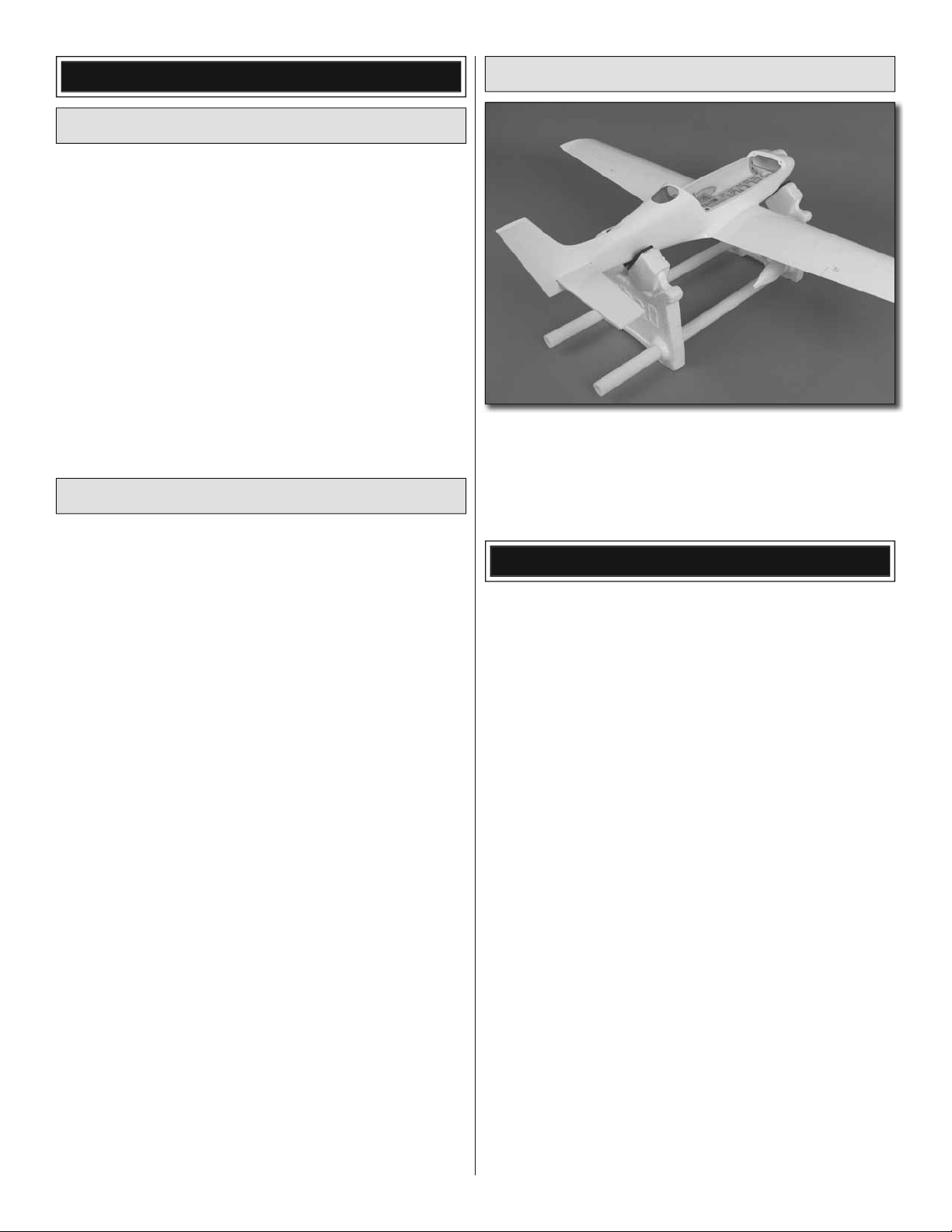
Building Stand
A building stand or cradle comes in handy during the build.
We use the Robart Super Stand II (ROBP1402) for all our
projects in R&D, and it can be seen in pictures throughout
this manual.
Here is a list of optional tools that will help you build the
Cirrus SR22 ARF:
1/2 oz. [15g] Medium Pro CA+ (GPMR6007)
❏
2 oz. [57g] spray CA activator (GPMR6035)
❏
4 oz. [113g] aerosol CA activator (GPMR6034)
❏
CA applicator tips (HCAR3780)
❏
CA debonder (GPMR6039)
❏
Pro 6-minute epoxy (GPMR6045)
❏
Pro 30-minute epoxy (GPMR6047)
❏
Epoxy brushes 6, (GPMR8060)
❏
Mixing sticks (GPMR8055)
❏
Mixing cups (GPMR8056)
❏
Pliers with wire cutter (HCAR0630)
❏
Rotary tool reinforced cut-off wheel (GPMR8020)
❏
Hobby Heat™ micro torch II (HCAR0755)
❏
Precision Magnetic Prop Balancer (TOPQ5700)
❏
AccuThrow™ Defl ection Gauge (GPMR2405)
❏
CG Machine™ (GPMR2400)
❏
Hobbico Flexible 18" Ruler Stainless Steel (HCAR0460)
❏
Top Flite MonoKote heat gun (TOPR2000)
❏
Hobbico Pin Vise 1/16 Collet w/6 Bits (HCAR0696)
❏
Great Planes Heat Shrink Tubing 3/8x3" (3) (GPMM1060)
❏
Woodland Scenics Low Temp Foam Glue Gun
❏
(WOOU1445)
Denatured alcohol (for epoxy clean up)
❏
IMPORTANT BUILDING NOTES
• When you see the term test fi t in the instructions, it means
that you should fi rst position the part on the assembly without
using any glue, then slightly modify or custom fi t the part as
necessary for the best fi t.
• Whenever the term “glue” is written, you should rely upon
your experience to decide what type of glue to use. When
a specifi c type of adhesive works best for that step, the
instructions will make a recommendation.
• Photos and sketches are placed before the step they refer
to. Frequently you can study photos in following steps to get
another view of the same parts.
• The Cirrus SR22 is factory-covered with Top Flite Jet White
MonoKote fi lm (TOPQ0204). Should repairs ever be required,
MonoKote can be patched with additional MonoKote
purchased separately. MonoKote is packaged in six-foot rolls,
but some hobby shops also sell it by the foot. If only a small
piece of MonoKote is needed for a minor patch, perhaps a
fellow modeler would give you some. MonoKote is applied
with a model airplane covering iron, but in an emergency a
regular iron could be used. A roll of MonoKote includes full
instructions for application.
• The stabilizer and wing incidences and engine thrust angles
have been factory-built into this model. However, some
technically-minded modelers may wish to check these
measurements anyway. To view this information visit the web
site at www.greatplanes.com and click on “Technical Data.”
Due to manufacturing tolerances which will have little or no
effect on the way your model will fl y, please expect slight
deviations between your model and the published values.
4
KIT INSPECTION
Before starting to build, inspect the parts to make sure they
are of acceptable quality. If any parts are missing or are not of
acceptable quality, or if you need assistance with assembly,
contact Product Support. When reporting defective or
missing parts, use the part names exactly as they are written
in the Kit Contents list.
Great Planes Product Support
3002 N. Apollo Drive, Suite 1
Champaign, IL 61822
Telephone: (217) 398-8970, ext. 5
Fax: (217) 398-7721
E-mail: airsupport@greatplanes.com
Mail parts orders and payments by personal check to:
Hobby Services
3002 N. Apollo Drive, Suite 1
Champaign, IL 61822
Be certain to specify the order number exactly as listed in
the Replacement Parts List. Payment by credit card or
personal check only; no C.O.D.
If additional assistance is required for any reason, contact
Product Support by telephone at (217) 398-8970, or by
e-mail at productsupport@greatplanes.com.
REPLACEMENT PARTS LIST
Order No. Description
ORDERING REPLACEMENT PARTS
Replacement parts for the Great Planes Cirrus SR22 ARF
are available using the order numbers in the Replacement
Parts List that follows. The fastest, most economical service
can be provided by your hobby dealer or mail-order company.
To locate a hobby dealer, visit the Great Planes web site
at www.greatplanes.com. Choose “Where to Buy” at the
bottom of the menu on the left side of the page. Follow the
instructions provided on the page to locate a U.S., Canadian
or International dealer.
Parts may also be ordered directly from Hobby Services
by calling (217) 398-0007, or fax at (217) 398-7721, but full
retail prices and shipping and handling charges will apply.
Illinois and Nevada residents will also be charged sales tax.
If ordering via fax, include a Visa® or MasterCard® number
and expiration date for payment.
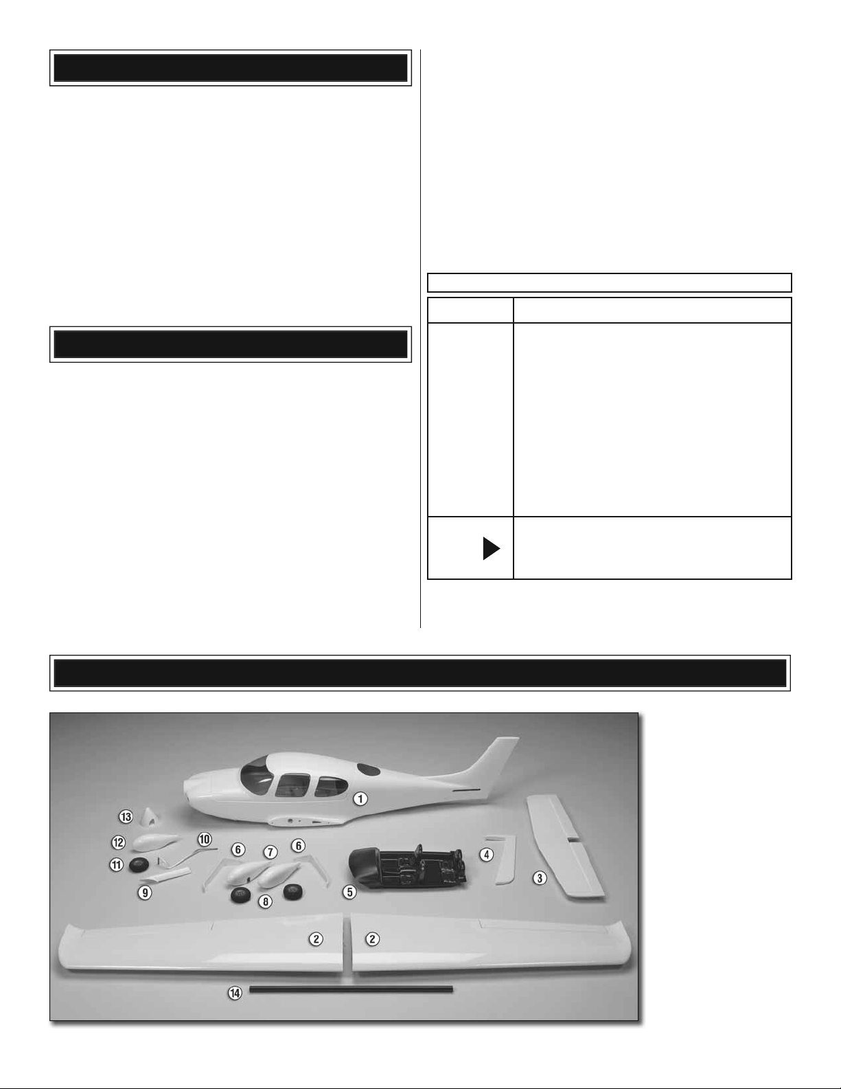
KIT CONTENTS
GPMA4035
GPMA4036
GPMA4037
GPMA4038
GPMA4039
GPMA4040
GPMA4041
GPMA4042
GPMA4043
GPMA4044
GPMA4045
NOTE
FUSELAGE
WING
TAIL SURFACES
HATCH
WHEELPANTS
NOSE GEAR FAIRING
MAIN GEAR SET
NOSE GEAR
DECALS
WING JOINER ROD
SPINNER
Full-size plans are not available.
You can download a copy of this
manual at www.greatplanes.com.
1. Fuselage, canopy hatch
2. Wing
3. Horizontal stabilizer
(stab) with elevators
4. Rudder
5. Cockpit interior
6. Main landing gear
7. Main gear wheel pants
8. Main wheels
9. Nose gear fairing
10. Nose gear
11. Nose wheel
12. Nose wheel pant
13. Spinner
14. Wing tube
5
BUILDING INSTRUCTIONS
Preparations
1. If you have not done so already, remove the major
❏
parts of the kit from the box and inspect for damage. If any
parts are damaged or missing, contact Product Support at
the address or telephone number listed in the “Kit Inspection”
section on page 5.
2. Carefully remove the tape and separate all the control
❏
surfaces. Use a covering iron with a covering sock on high
heat to tighten the covering if necessary. Apply pressure over
sheeted areas to thoroughly bond the covering to the wood.
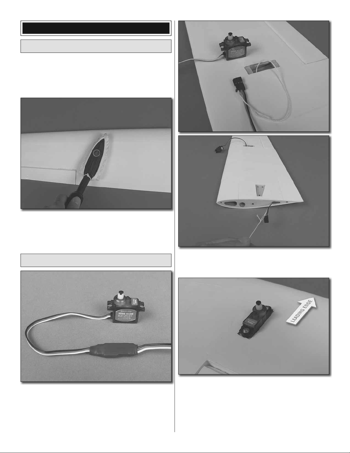
Assemble the Wing Panels
1. Attach a 12" [305mm] servo extension to each aileron
❏
servo. Secure the connections using tape, heat shrink tubing
(not included) or special clips designed for that purpose.
2. Locate the strings taped inside the aileron servo bays
❏
and tie the ends of the strings to the servo extensions. Use
the string to pull the servo leads through the wing ribs.
3. Install the rubber grommets and eyelets included with
❏
the servos. Position the servos in the aileron servo bays in
the orientation shown. Drill 1/16" [1.6mm] holes through
the servo mounting tabs. Thread a servo mounting screw
(included with the servos) into each hole and back it out.
Apply a drop of thin CA to each hole to harden the wood.
When the glue has dried, install the servos using the screws
included with the servos.
6
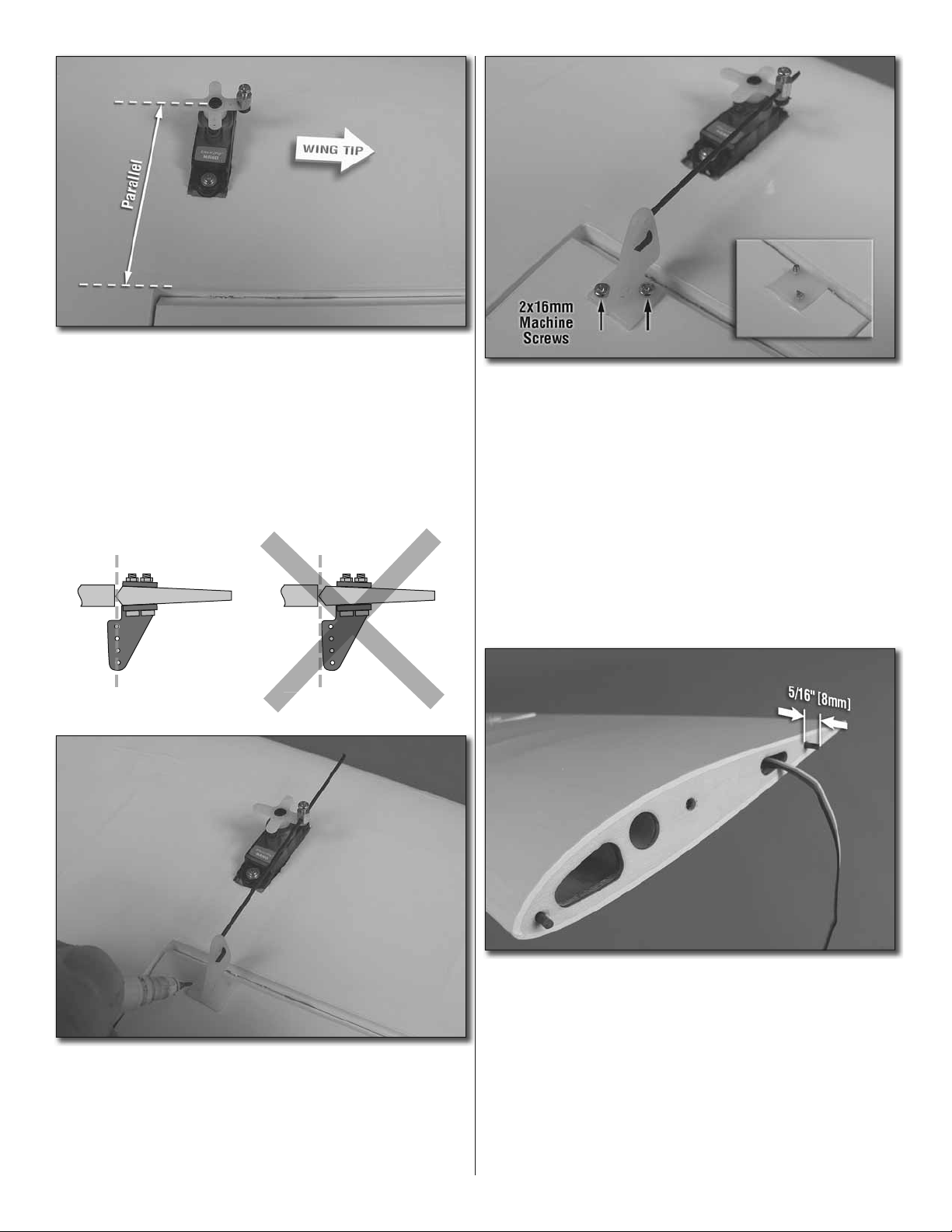
4. Install a screw lock pushrod connector into the outer
❏
hole of the long servo arm as shown with a nylon screw
lock retainer. Loosely thread a 2x4mm machine screw into
the connector. Center the servos with your radio system and
install the servo arm onto the servo parallel to the aileron
hinge line as shown with the connector toward the wing
tip. Be sure to reinstall the servo arm screw into the servo.
Repeat this step for the other aileron servo.
CORRECT INCORRECT
Hinge Line Hinge Line
6. Drill 5/64" [2mm] holes at the marks you made through
❏
the ailerons. Apply a couple drops of thin CA glue to each
hole to harden the wood surrounding the holes. When the
glue has dried, install the control horns onto the ailerons
using four 2x16mm machine screws and control horn
backplates. The ends of the screws can be cut off beyond
the control horns.
7. Position the aileron in the neutral position and tighten
❏
the screw in the screw lock pushrod connector against the
pushrod with threadlocking compound. The excess pushrod
beyond the pushrod connector can be cut off.
5. Connect the Z-bend end from a 90mm aileron pushrod
❏
into the second outer hole of a control horn. Insert the
other end into the screw lock pushrod connector. Align the
pushrod perpendicular to the hinge line and align the holes
in the control horns directly over the aileron hinge line. Mark
the location of the control horn mounting holes. Repeat this
step for the other aileron servo.
8. Use medium or thick CA to glue the carbon anti-rotation
❏
pins into the wing root ribs. The pins should protrude beyond
the ribs approximately 5/16" [8mm].
7
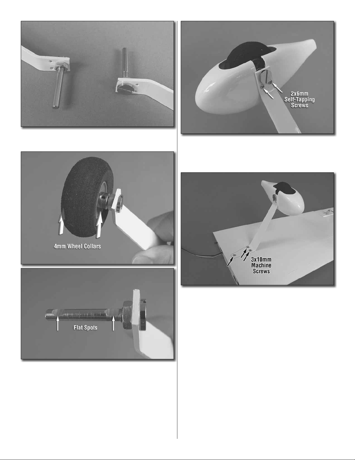
9. Install the axles onto the landing gear legs using the
❏
included landing gear nuts and threadlocking compound.
12. Thread a 2x6mm self-tapping screw into each hole in
❏
the wheel pants and back it out. Apply a drop of thin CA to
each hole and allow the glue to dry. Install the wheel pants
onto the landing gear with four 2x6mm self-tapping screws.
13. Bolt the landing gear legs to the wing panels using
❏
six 3x10mm machine screws and threadlocking compound.
10. Slide a 4mm wheel collar onto each axle followed
❏
by a main wheel and another 4mm wheel collar. Mark the
location of the screw holes in the wheel collars onto the
axles. Remove the wheel collars and wheels and use a fi le
or rotary tool to grind fl at spots onto the axles at the marks
you made.
11. Install the wheel collars and main wheels onto the
❏
axles. Secure the collars onto the axles with 3mm set screws
and threadlocking compound. Be sure that the wheels rotate
freely. Oil them if necessary.
8
 Loading...