

Great Planes GPMA1160 User Manual
WARRANTY
Great Planes
®
Model Manufacturing Co. guarantees this kit to be free from defects in both material and workmanship at the date of
purchase.This warranty does not cover any component parts damaged by use or modification. In no case shall Great Planes’ liability
exceed the original cost of the purchased kit. Further, Great Planes reserves the right to change or modify this warranty without notice.
In that Great Planes has no control over the final assembly or material used for final assembly, no liability shall be assumed nor
accepted for any damage resulting from the use by the user of the final user-assemb led product.By the act of using the user-assembled
product, the user accepts all resulting liability.
If the buyer is not prepared to accept the liability associated with the use of this product, the buyer is advised to return this
kit immediately in new and unused condition to the place of purchase.
To make a warranty claim send the defective part or item to Hobby Services at the address below:
Hobby Services
3002 N. Apollo Dr. Suite 1
Champaign IL 61822 USA
Include a letter stating your name, return shipping address, as much contact information as possible (daytime telephone number, fax
number, e-mail address), a detailed description of the problem and a photocopy of the purchase receipt. Upon receipt of the package
the problem will be evaluated as quickly as possible.
READ THROUGH THIS MANUAL BEFORE STARTING
CONSTRUCTION. IT CONTAINS IMPORTANT WARNINGS
AND INSTRUCTIONS CONCERNING THE ASSEMBLY
AND USE OF THIS MODEL.
GPMZ0201 for GPMA1160 V1.0© Copyright 2004
Champaign, Illinois
(217) 398-8970, Ext 5
airsupport@greatplanes.com
INSTRUCTION MANUAL
Wingspan: 48 in [1220mm]
Wing Area: 383 sq in [24.7 dm2]
Weight: 3-1/4 lb [1470 g]
Wing Loading: 19.5 oz/sq ft [60 g/dm
2
]
Length: 39 in [990mm]
Radio: 4-channel with three mini servos
Motor: 550 size
Electronic Speed Control: 30 amp
INTRODUCTION................................................................2
SAFETY PRECAUTIONS..................................................2
BATTERY CHARGER OPTIONS ......................................3
ADDITIONAL ITEMS REQUIRED.....................................3
Hardware and Accessories ..........................................3
Adhesives and Building Supplies.................................3
Optional Supplies and Tools ........................................4
IMPORTANT BUILDING NOTES.......................................4
COMMON ABBREVIATIONS............................................4
KIT INSPECTION...............................................................5
KIT CONTENTS .................................................................5
ORDERING REPLACEMENT PARTS...............................6
PREPARATIONS................................................................7
ASSEMBLE THE WING.....................................................7
Install the Ailerons .......................................................7
Join the Wing Halves...................................................8
ASSEMBLE THE FUSELAGE...........................................9
Mount the Wing............................................................9
Mount the Stabilizer and Fin ........................................9
RADIO INSTALLATION...................................................12
Install the Control Horns............................................12
Install the Servos.......................................................12
MOUNT THE COWL AND PROP....................................15
MOUNT THE LANDING GEAR.......................................16
FINISH THE MODEL........................................................17
Install the Canopy......................................................17
Install the Battery Hatch ............................................18
Apply the Decals ........................................................19
GET THE MODEL READY TO FLY..................................19
Check the Control Directions.....................................19
Set the Control Throws..............................................20
Balance the Model (C.G.)..........................................20
Balance the Model Laterally......................................21
PREFLIGHT.....................................................................21
Identify Your Model.....................................................21
Charge the Batteries ..................................................21
Balance Propellers....................................................21
PROPER CARE OF YOUR MOTOR ...............................21
PERFORMANCE TIPS....................................................22
Ground Check...........................................................22
Range Check.............................................................22
MOTOR SAFETY PRECAUTIONS .................................22
AMA SAFETY CODE......................................................22
CHECK LIST ...................................................................23
FLYING............................................................................23
Takeoff.........................................................Back Cover
Flight...........................................................Back Cover
Landing.......................................................Back Cover
The Great Planes Super Sportster kits have been a favorite
among pilots since 1984. For many pilots the Super
Sportster was their first low wing plane. Now, Great Planes
brings you the Super Sportster tradition in an electric
version. Following the lines of the Super Sportster 20, the
Super Sportster EP has been lightened to accommodate
electric power without sacrificing performance. If you’re
ready to continue the Super Sportster tradition without the
fuss and mess of a glow engine, the Super Sportster EP is
just what you need.
For the latest technical updates or manual corrections to the
Super Sportster EP ARF visit the Great Planes web site at
www.greatplanes.com. Open the “Airplanes” link, then
select the Super Sportster EP ARF.If there is new technical
information or changes to this model a “tech notice” box will
appear in the upper left corner of the page.
We urge you to join the AMA (Academy of Model Aeronautics)
and a local R/C club.The AMA is the governing body of model
aviation and membership is required to fly at AMA clubs.
Though joining the AMA provides many benefits, one of the
primary reasons to join is liability protection. Coverage is not
limited to flying at contests or on the club field. It even applies
to flying at public demonstrations and air shows. Failure to
comply with the Safety Code (excerpts printed in the back of
the manual) may endanger insurance coverage. Additionally,
training programs and instructors are available at AMA club
sites to help you get started the right way. There are over
2,500 AMA chartered clubs across the countr y. Contact the
AMA at the address or toll-free phone number below:
Academy of Model Aeronautics
5151 East Memorial Drive
Muncie, IN 47302-9252
Tele.(800) 435-9262
Fax (765) 741-0057
Or via the Internet at:
http://www.modelaircraft.org
IMPORTANT!!! Two of the most important things you can do
to preserve the radio controlled aircraft hobby are to avoid
flying near full-scale aircraft and avoid flying near or over
groups of people.
1. Your Super Sportster EP should not be considered a toy,
but rather a sophisticated, working model that functions very
much like a full-size airplane. Because of its performance
capabilities, the Super Sportster EP, if not assembled and
operated correctly, could possibly cause injury to yourself or
spectators and damage to property.
PRO TECT YOUR MODEL,Y OURSELF
& OTHERS...FOLLOW THESE
IMPORTANT SAFETY PRECAUTIONS
AMA
INTRODUCTION
TABLE OF CONTENTS
2
2. You must assemble the model according to the
instructions. Do not alter or modify the model, as doing so
may result in an unsafe or unflyable model. In a few cases
the instructions may differ slightly from the photos.In those
instances the written instructions should be considered
as correct.
3. You must take time to build straight, true and strong.
4. You must use an R/C radio system that is in firstclass condition.
5. Y ou m ust correctly install all R/C and other components so
that the model operates correctly on the ground and in the air.
6. You must check the operation of the model before every
flight to insure that all equipment is operating and that the
model has remained structurally sound. Be sure to check
clevises or other connectors often and replace them if they
show any signs of wear or fatigue.
7. If you are not an experienced pilot or have not flown this
type of model before, we recommend that you get the
assistance of an experienced pilot in your R/C club for your
first flights.If you’re not a member of a club, your local hobb y
shop has information about clubs in your area whose
membership includes experienced pilots.
8. WARNING: The cowl and wheel pants included in this
kit are made of fiberglass, the fibers of which may cause
eye, skin and respiratory tract irritation. Never blow into a
part (wheel pant, cowl) to remove fiberglass dust, as the
dust will blow back into your eyes. Always wear safety
goggles, a particle mask and rubber gloves when grinding,
drilling and sanding fiberglass parts. Vacuum the parts and
the work area thoroughly after working with fiberglass parts.
Remember:Take y our time and f ollo w the instructions to
end up with a well-built model that is straight and true.
A fully charged battery pack will provide an initial “surge” of
power during the first 15 to 30 seconds of the motor run.
Then the power output stays f airly steady for the ne xt se ver al
minutes before dropping off quickly. If you do not “peakcharge” your battery, it will not deliver that initial surge
necessary for a good takeoff and climb-out.There are three
easy ways to peak-charge your battery pack.
1. The easiest way is with a “peak-detecting” battery
charger.This type of charger will charge your batter y until it
is fully charged, then automatically shut off. Using a peakdetecting charger reduces the chances of damaging the
batteries from over-charging. We recommend the Great
Planes Triton™ DC Peak Charger (GPMM3150) to keep
your batteries in good condition.
2. The second method of charging your motor batteries is
to monitor the voltage of your battery pack with a voltmeter
while charging. This method is only recommended for
NiCd batteries. Your charger may have sockets into which
you may plug a voltmeter. If not, you may insert the probes
from the voltmeter into the rear of the battery plug, making
contact with the metal contacts.As your battery charges, the
voltage will gradually increase. When the battery is fully
charged, the voltage will start to drop. At this point your
battery is fully charged. We recommend the Hobbico®905
AC/DC Multi-Charger (HCAP0150).
3. The third (and least reliable) method of peak-charging
your battery pack is by checking its temperature. This
method is only recommended for NiCd batteries. As the
battery charges it will remain cool until it is fully charged.
When it reaches the fully charged state, it will rapidly build
up heat. You can feel this heat with your hand. As soon as
the pack starts to noticeably warm up, disconnect it from the
charger. Do not continue charging if the battery pack is
hot! Overcharging will damage your battery pack and can
result in an explosion.
In addition to the items listed in the “BATTERY CHARGER
OPTIONS” section, the following is the list of hardware and
accessories required to finish the Super Sportster EP ARF.
Order numbers are provided in parentheses.
❏ 4-channel radio with three mini ser vos
❏ 6" [150mm] ser vo extension (HCAM2701 for Futaba
®
)
In addition to common household tools and hobby tools, this
is the “short list”of the most important items required to build
the Super Sportster EP.
Great Planes Pro™CA and Epoxy
glue are recommended.
❏ 1/2 oz. [15g] Thin Pro CA (GPMR6001)
❏ Pro 30-minute epoxy (GPMR6047)
❏ Drill bits: 1/32" [.8mm], 1/16" [1.6mm], 5/64" [2mm], 3/32"
[2.4mm], 1/8" [3.2mm]
❏ #1 Hobby knife (HCAR0105)
Adhesives and Building Supplies
Hardware and Accessories
ADDITIONAL ITEMS REQUIRED
BATTERY CHARGER OPTIONS
We, as the kit manuf acturer, provide y ou with a top quality,
thoroughly tested kit and instructions, but ultimately the
quality and flyability of your finished model depends on
how you build it; therefore, we cannot in any way
guarantee the performance of your completed model, and
no representations are expressed or implied as to the
performance or safety of your completed model.
3
❏ #11 blades (5-pack, HCAR0211)
❏ Medium T-pins (100, HCAR5150)
❏ Builder’s Triangle Set (HCAR0480)
❏ 36" metal ruler (HCAR0475)
❏ Denatured alcohol (for epoxy clean up)
Here is a list of optional tools mentioned in the manual that
will help you build the Super Sportster EP.
❏ Stick-on segmented lead weights (GPMQ4485)
❏ Top Flite
®
MonoKote®sealing iron (TOPR2100)
❏ Top Flite Hot Sock
™
iron cover (TOPR2175)
❏ Top Flite MonoKote heat gun (TOPR2000)
❏ Pro 6-minute epoxy (GPMR6045)
❏ 2 oz. [57g] spray CA activator (GPMR6035)
❏ R/C-56 canopy glue (JOZR5007)
❏ CA applicator tips (HCAR3780)
❏ CA debonder (GPMR6039)
❏ Epoxy brushes (6, GPMR8060)
❏ Mixing sticks (50, GPMR8055)
❏ Mixing cups (GPMR8056)
❏ Cur ved-tip canopy scissors for trimming plastic
parts (HCAR0667)
❏ Robar t Super Stand II (ROBP1402)
❏ Masking tape (TOPR8018)
❏ K & S #801 Kevlar thread (for stab alignment)
❏ CG Machine
™
(GPMR2400)
❏ Precision Magnetic Prop Balancer™ (TOPQ5700)
❏ AccuThrow
™
Deflection Gauge (GPMR2405)
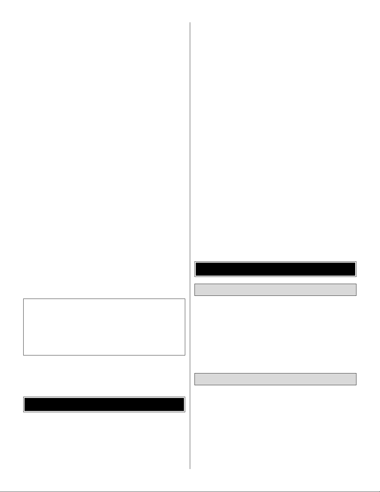
• There are two types of screws used in this kit:
Sheet metal screws are pointed
and have a coarse thread.
Machine screws have a squared
off end and a fine thread.
Both screws are designated by a number, the diameter, and
the length. For example a 3 x 8mm screw has a diameter of
3mm and a length of 8mm.
• When you see the term
test fit
in the instructions, it means
that you should first position the part on the assembly
without using any glue, then slightly modify or
custom fit
the part as necessar y for the best fit.
• Whenever the term
glue
is written you should rely upon
your experience to decide what type of glue to use.When a
specific type of adhesive works best for that step, the
instructions will make a recommendation.
• Whenever just
epoxy
is specified you may use
either
30-minute (or 45-minute) epoxy or6-minute epoxy. When
30-minute epoxy is specified it is highly recommended that
you use only 30-minute (or 45-minute) epoxy, because you
will need the working time and/or the additional strength.
• Photos and sketches are placed before the step they
refer to. Frequently you can study photos in following steps
to get another view of the same parts.
• The stabilizer and wing incidences and motor thrust angles
have been factory-built into this model. However, some
technically-minded modelers may wish to check these
measurements anyway.To vie w this inf ormation visit the web
site at www.greatplanes.com and click on “Technical Data.”
Due to manufacturing tolerances which will have little or no
effect on the way your model will fly, please expect slight
deviations between your model and the published values.
Fuse = Fuselage
Stab = Horizontal Stabilizer
Fin = Vertical Fin
LE = Leading Edge
TE = Trailing Edge
LG = Landing Gear
Ply = Plywood
" = Inches
mm = Millimeters
SHCS = Socket Head Cap Screw
COMMON ABBREVIATIONS
IMPORTANT BUILDING NOTES
Adhesives and Building Supplies
4
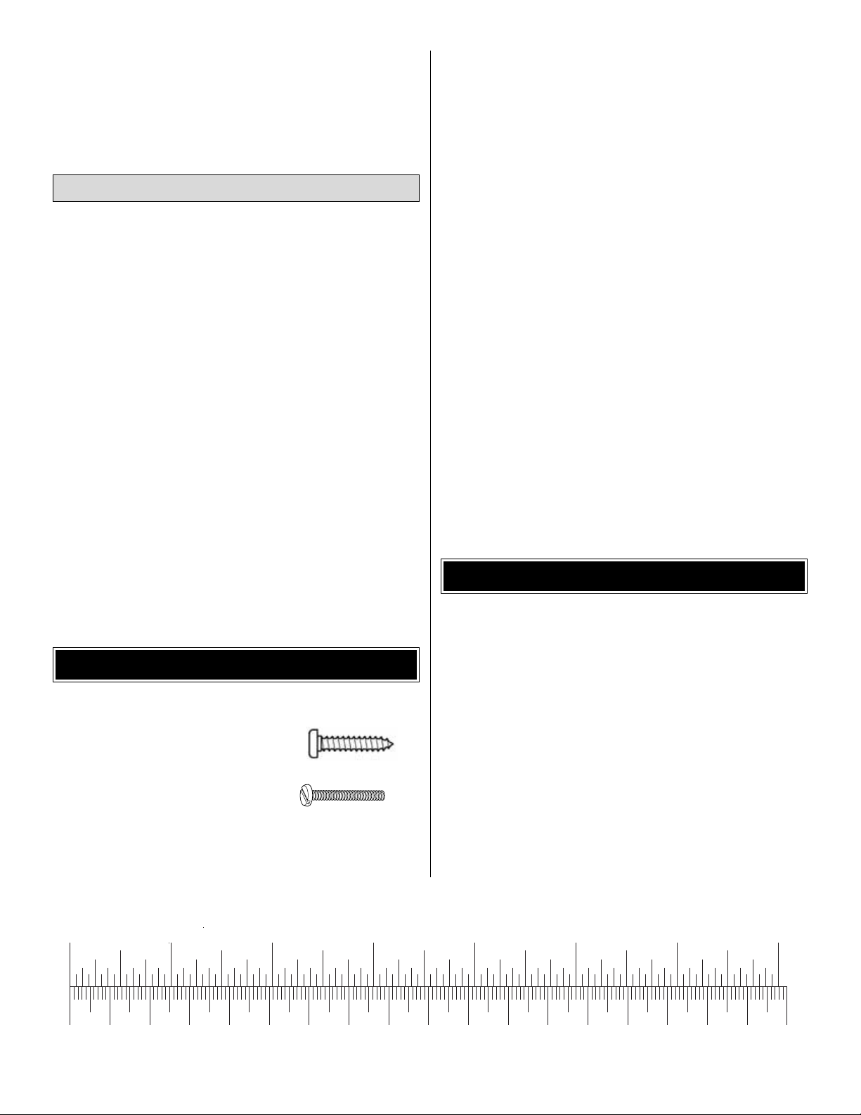
0" 1" 2" 3" 4" 5" 6" 7"
0 10 20 30 40 50 60 70 80 90 100 110 120 130 140 150 160 170 180
Inch Scale
Metric Scale
To convert inches to millimeters, multiply inches by 25.4
5
Before starting to build, take an inventory of this kit to make sure it is complete, and inspect the parts to make sure they
are of acceptable quality.If any parts are missing or are not of acceptable quality, or if y ou need assistance with assemb ly,
contact Product Support. When repor ting defective or missing parts, use the part names exactly as they are written in
the Kit Contents list.
Great Planes Product Support:
3002 N Apollo Drive, Suite 1
Champaign, IL 61822
Telephone: (217) 398-8970, ext. 5
Fax: (217) 398-7721
E-mail:
airsupport@greatplanes.com
KIT INSPECTION
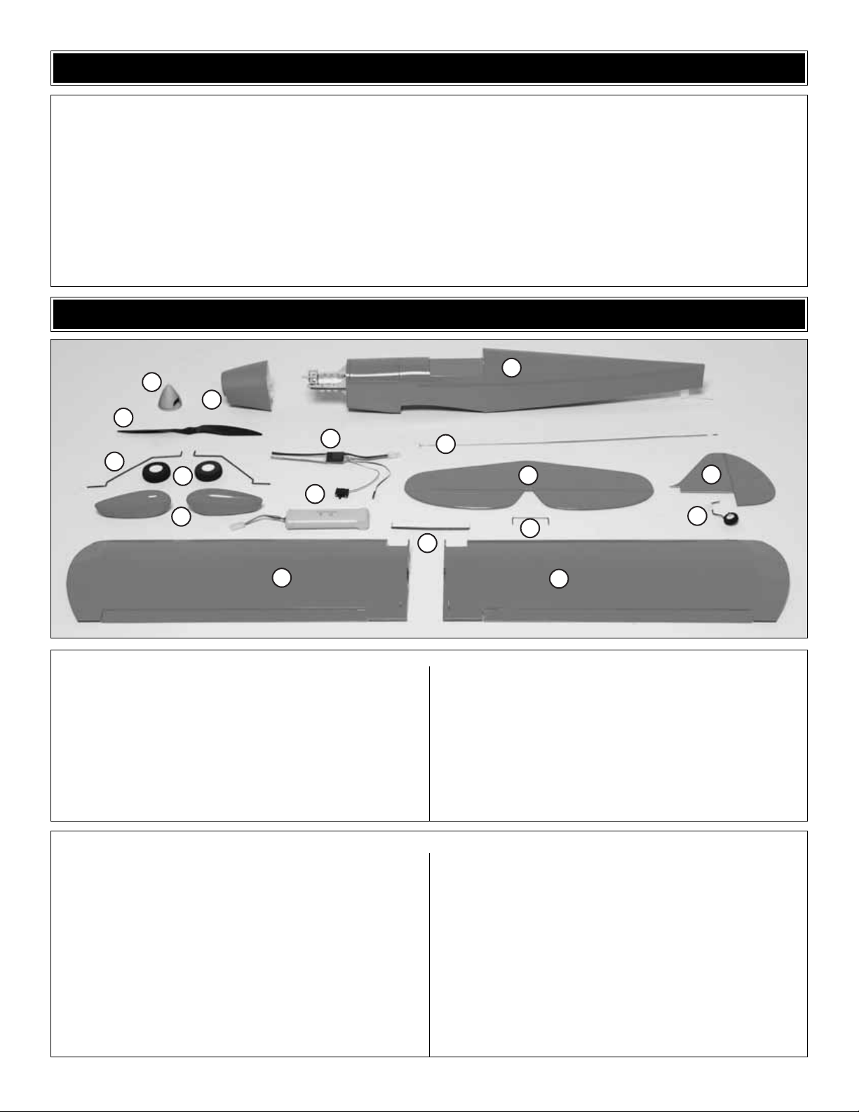
1 Fuselage
2 Left Wing Panel
3 Right Wing Panel
4 Stabilizer and Elevator
5 Fin and Rudder
6 Elevator Joiner Wire
7 Tail Gear Assembly
8 Wing Joiners (2)
9 Cowl
10 Spinner
11 Prop
12 Electronic Speed Control
13 Main Landing Gear
14 Wheels (2)
15 Wheel Pants (2)
16 Motor Battery
17 Pushrods (2)
Kit Contents (Photographed)
Canopy (1)
Control Horn (2)
Collet Wire (1)
3x10mm Sheet Metal Screw (4)
Nylon Landing Gear Strap (2)
Plywood Wheel Pant Mounting Plate (2)
Plywood Wheel Pant Retainer (2)
2.5x8mm Sheet Metal Screw (8)
3mm Wheel Collar (4)
3x4mm Machine Screw (4)
3x30mm Machine Screw (2)
3mm Washer (2)
Plywood Aileron Servo Tray (1)
Hook & Loop Material (1)
Nylon Torque Rod Horns (2)
Nylon Clevis (2)
2-56x4" [100mm] Aileron Pushrods (2)
Hinge Strap (1)
2x10mm Machine Screw (4)
1.7mm Wheel Collar (2)
2.5mm Set Screw (2)
Hex Wrench (1)
Rubber Bands (2)
Kit Contents (Not Photographed)
KIT CONTENTS
1
10
9
11
12
13
14
16
15
17
4
6
8
5
7
2
3
6
ORDERING REPLACEMENT PARTS
Replacement parts for the Great Planes Super Sportster EP ARF are available using the order numbers in the
Replacement Parts List that follows.The fastest, most economical ser vice can be provided by your hobby dealer or mailorder company.
To locate a hobby dealer, visit the Great Planes web site at www.greatplanes.com.Choose “Where to Buy” at the bottom of
the menu on the left side of the page.Follow the instructions provided on the page to locate a U .S ., Canadian or International
dealer. If a hobby shop is not available, replacement parts may also be ordered from Tower Hobbies at
www.towerhobbies.com, or by calling toll free (800) 637-6050.
Parts may also be ordered directly from Hobby Services by calling (217) 398-0007, or via facsimile at (217) 398-7721, but
full retail prices and shipping and handling charges will apply. Illinois and Nevada residents will also be charged sales tax.
If ordering via fax, include a Visa
®
or MasterCard®number and expiration date for payment.
Mail parts orders and payments by personal check to:
Hobby Services
3002 N Apollo Drive, Suite 1
Champaign IL 61822
Be certain to specify the order number exactly as listed in the Replacement Parts List.Payment b y credit card or personal
check only; no C.O.D.
If additional assistance is required for any reason contact Product Support by e-mail at productsupport@greatplanes.com,
or by telephone at (217) 398-8970.
Replacement Parts List
Order Number Description How to Purchase
Missing pieces ................................................Contact Product Support
Instruction manual...........................................Contact Product Support
Full-size plans.................................................Not available
Kit parts listed below .......................................Hobby Supplier
GPMA2750............Wing Kit
GPMA2751............Fuselage Kit
GPMA2752............Tail Set
GPMA2753............Landing Gear
GPMA2754............Cowl
GPMA2755............Canopy
GPMA2756............Wheel Pants
GPMA2759............Decal Sheet
GPMA2344............SC2100 7-Cell Batter y
GPMQ4790 ...........Spinner
GPMQ1681 ...........Propeller
GPMG0234 ...........Gearbox
GPMG0706 ...........Motor
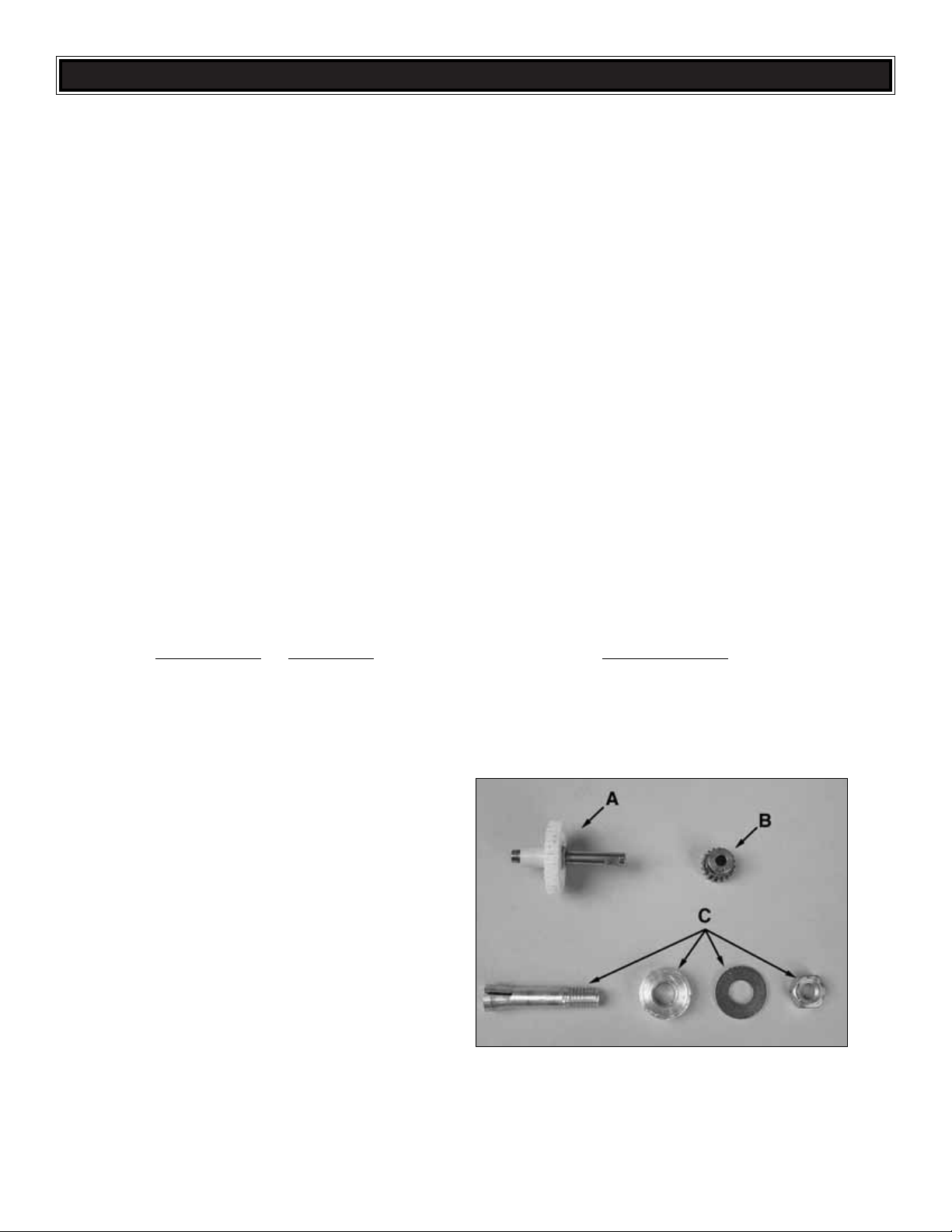
GPMG0862 ...........Spur Gear/Shaft (A)
GPMG0239 ...........Pinion Gear (B)
GPMQ4622 ...........Prop Adapter (C)
❏ 1. If you have not done so already, remove the major
parts of the kit from the box (wing, fuselage, tail parts, etc.)
and inspect them for damage. If any parts are damaged or
missing, contact Product Support at the address or
telephone number on the front cover.
❏ 2. Remove the masking tape and separate the ailerons
from the wing, the rudder from the fin and the elevator from
the stabilizer. If necessary, use a covering iron set on
medium/high to tighten the covering. Apply pressure over
sheeted areas to thoroughly bond the covering to the wood.
❏ 1. From the 2" x 9" [50mm x 230mm]
CA hinge strip, cut six 3/4" x 1" [19mm x
25mm] hinges. Cut off the corners to
make insertion easier.
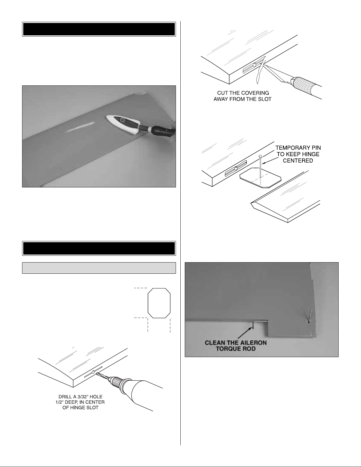
❏❏2. Dr ill a 3/32" [2.4mm] hole, 1/2" [13mm] deep in the
center of each hinge slot to allow the CA to “wick”in.Followup with a #11 blade to clean out the slots. Hint: If you have
one, use a high-speed rotary tool to drill the holes.
❏❏3. Use a sharp #11 blade to cut a strip of covering
from all the hinge slots in the wing half and aileron.
❏❏4. Test fit the ailerons to the wing with the hinges. If
the hinges don’t stay centered, stick a pin through the
middle of the hinges to hold them in position.
❏❏5.Clean the aileron torque rod with denatured alcohol
to remove any contaminants.
❏❏6. Mix up a small amount of epoxy. Using a tooth pick,
apply epoxy in the aileron torque rod hole and along the
groove in the leading edge of the aileron. Before the epoxy
cures, join the aileron to the wing. Remove any pins you may
have inserted into the hinges. Adjust the aileron so there is a
very small gap between the LE of the aileron and the wing.
The gap should be small – just enough to see light through or
to slip a piece of paper through. Clean up any excess epoxy
using a paper towel dampened with denatured alcohol.
Install the Ailerons
ASSEMBLE THE WING
PREPARATIONS
7
1"
[25mm]
3/4"
[20mm]

❏❏7. Apply six drops of thin CA to the top and bottom of
each hinge. Do not use CA accelerator. After the CA and
epoxy have fully hardened, test the hinges by pulling on
the ailerons.
❏ 8. Now join the other aileron and wing half using the
same procedure.
❏ 1. Use epoxy to glue the two plywood wing joiners
together. Wipe off the excess epoxy with a paper towel
dampened with denatured alcohol. Use clamps to hold the
two joiners together until the epoxy cures.
❏ 2. Use a bar sander with coarse sandpaper to true the
edges and remove any excess hardened epoxy from the
wing joiner. Without using any glue, temporarily join the
wings with the joiner. Make adjustments as necessary for a
good fit. Note: The dihedral angle is factory-set and
determined by the angle of the joiner and the joining ribs on
the ends of the wing halves. However, you may confirm the
dihedral by placing one wing panel flat on the workbench
and measuring the distance between the bottom of the rib
on the end of the other panel and the bench. The distance
should be 1" [25mm], but a small variance is acceptable. If
the wing doesn’t fit well or if you can’t get close enough to
the dihedral specified, there may be excess glue inside the
wing or irregularities on the joiner.Use coarse sandpaper to
true the edges and bevel the corners of the joiner and/or use
a hobby knife to remove any glue from the joiner openings
in the ribs on the end of the wing halves.
❏ 3. Prepare 1/2 oz. of 30-minute epoxy. Working quickly,
thoroughly coat the inside of both wing halves where the
joiner fits and one half of the joiner with epoxy. Making
certain the joiner is upright, insert the coated end into one of
the wing halves.Coat the other end of the joiner and the root
ribs with the remainder of the epoxy. Join the wing halves
tightly, holding them together. Use a paper towel dampened
with denatured alcohol to wipe away the excess epoxy that
comes out of the wing. Tightly hold the wing together with
several strips of masking tape, making certain both halves
are in full contact and the leading and trailing edges are
aligned. Let the wing set until the epoxy has cured.
❏ 4. Position the plywood aileron servo tray, centered over
the opening in the top of the wing. Use a fine-tip marker to
trace around the inside and outside of the tray.
Join the Wing Halves
8
1" [25.4mm]
 Loading...