

Page 1
WARRANTY
Great Planes
®
Model Manufacturing Co. guarantees this kit to be free from defects in both material and workmanship at the date of
purchase.This warranty does not cover any component parts damaged by use or modification. In no case shall Great Planes’ liability
exceed the original cost of the purchased kit. Further, Great Planes reserves the right to change or modify this warranty without notice.
In that Great Planes has no control over the final assembly or material used for final assembly, no liability shall be assumed nor
accepted for any damage resulting from the use by the user of the final user-assemb led product.By the act of using the user-assembled
product, the user accepts all resulting liability.
If the buyer is not prepared to accept the liability associated with the use of this product, the buyer is advised to return this
kit immediately in new and unused condition to the place of purchase.
To make a warranty claim send the defective part or item to Hobby Services at the address below:
Hobby Services
3002 N. Apollo Dr. Suite 1
Champaign IL 61822 USA
Include a letter stating your name, return shipping address, as much contact information as possible (daytime telephone number, fax
number, e-mail address), a detailed description of the problem and a photocopy of the purchase receipt. Upon receipt of the package
the problem will be evaluated as quickly as possible.
READ THROUGH THIS MANUAL BEFORE STARTING
CONSTRUCTION. IT CONTAINS IMPORTANT WARNINGS
AND INSTRUCTIONS CONCERNING THE ASSEMBLY
AND USE OF THIS MODEL.
GPMZ0177 for GPMA1159 V1.0© Copyright 2005
Champaign, Illinois
(217) 398-8970, Ext 5
airsupport@greatplanes.com
INSTRUCTION MANUAL
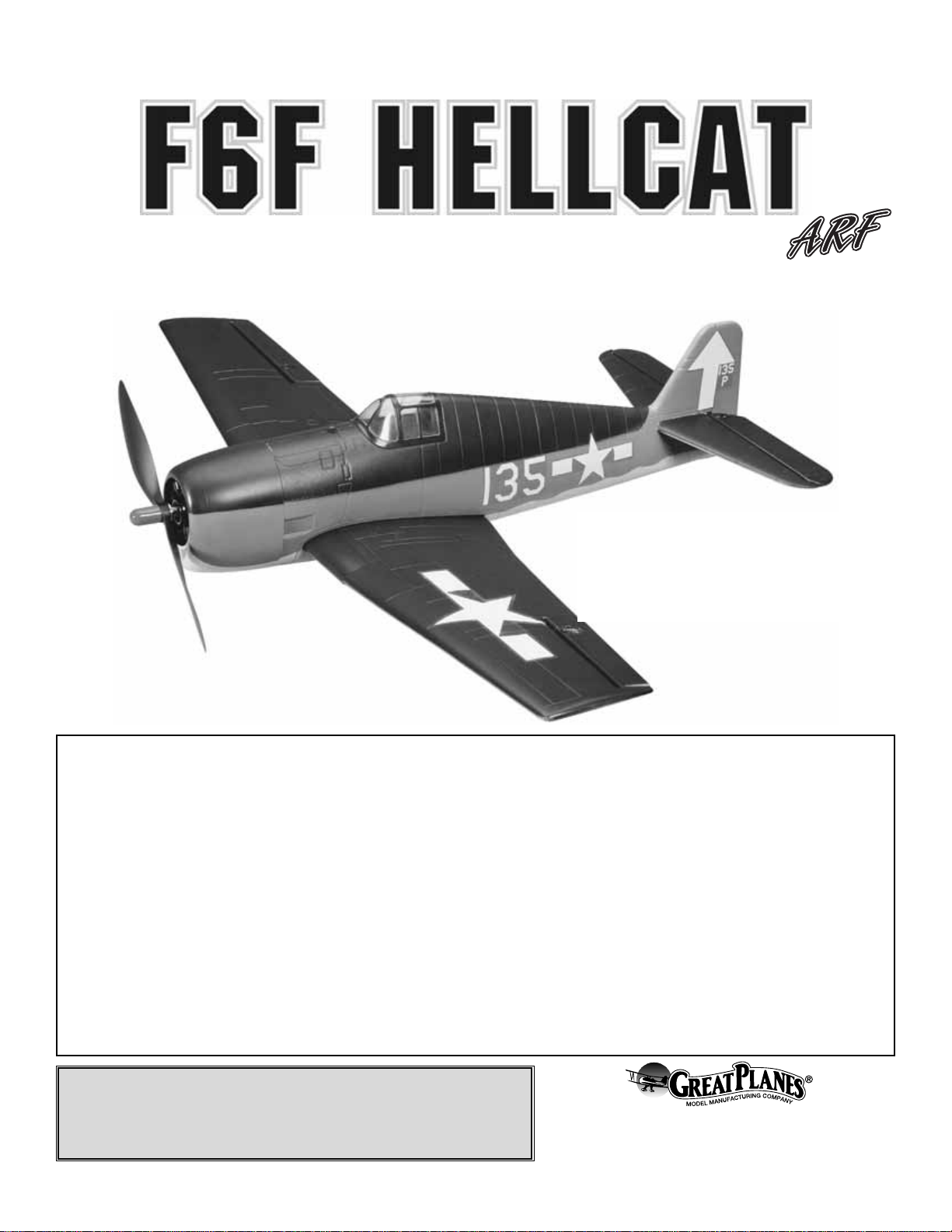
Wingspan: 32 in [810mm]
Wing Area: 190 sq in [12.3 dm2]
Weight: 16 oz [454g]
Wing Loading: 11 oz/ft2[34 g/dm2]
Length: 25 in [635mm]
Radio: 3 Channel w/ 2 micro (9g) servos and 10 Amp ESC
Power System: Included S280BB Motor with Gearbox
Page 2
INTRODUCTION................................................................2
SAFETY PRECAUTIONS..................................................3
ADDITIONAL ITEMS REQUIRED.....................................3
Required Radio Gear ...................................................3
Charger........................................................................3
Adhesives and Building Supplies.................................3
Optional Supplies and Tools ........................................4
IMPORTANT BUILDING NOTES.......................................4
COMMON ABBREVIATIONS............................................4
KIT INSPECTION...............................................................5
KIT CONTENTS .................................................................5
ORDERING REPLACEMENT PARTS...............................6
BUILDING INSTRUCTIONS..............................................7
Aileron Installation .......................................................7
Elevator Installation......................................................9
Motor Installation .......................................................10
Radio and Battery Installation....................................11
FINAL PREPARATIONS..................................................12
Propeller Installation ..................................................12
Main Wing Installation................................................12
Apply the Decals ........................................................13
GET THE MODEL READY TO FLY ................................13
Check the Control Directions.....................................13
Set the Control Throws..............................................13
Balance the Model (C.G.)..........................................13
Balance the Model Laterally......................................14
PREFLIGHT.....................................................................14
Identify Your Model.....................................................14
Charge the Batteries ..................................................14
Balance Propellers.....................................................14
Range Check.............................................................15
MOTOR SAFETY PRECAUTIONS..................................15
AMA SAFETY CODE ......................................................15
CHECK LIST ....................................................................15
FLYING.............................................................................16
Hand Launch .............................................................16
Flight..........................................................................16
Landing......................................................................16
Thank you for purchasing the Great Planes Hellcat Park
Flyer ARF! The Hellcat was one of the most important
aircraft to the US Navy during World War II. This fighter and
the F4U corsair became the most infamous pair among
Japanese pilots in the Pacific resulting in a ratio of kills to
losses of 11:1. Now you too can fly this outstanding heavy
fighter from the WWII era.
For the latest technical updates or manual corrections to the
Great Planes Hellcat Park Flyer ARF, visit the ElectriFly web
site at www.electrifly.com. Then, select the Great Planes
Hellcat Park Flyer ARF. If there is new technical information
or changes to this model, a “tech notice” box will appear in
the upper left corner of the page
We urge you to join the AMA (Academy of Model Aeronautics)
and a local R/C club.The AMA is the governing body of model
aviation and membership is required to fly at AMA clubs.
Though joining the AMA provides many benefits, one of the
primary reasons to join is liability protection. Coverage is not
limited to flying at contests or on the club field. It even applies
to flying at public demonstrations and air shows. Failure to
comply with the Safety Code (excerpts printed in the back of
the manual) may endanger insurance coverage. Additionally,
training programs and instructors are available at AMA club
sites to help you get started the right way. There are over
2,500 AMA chartered clubs across the countr y. Contact the
AMA at the address or toll-free phone number below:
Academy of Model Aeronautics
5151 East Memorial Drive
Muncie, IN 47302-9252
Tele. (800) 435-9262
Fax (765) 741-0057
Or via the Internet at:
http://www.modelaircraft.org
IMPORTANT!!! T w o of the most important things you can do
to preserve the radio controlled aircraft hobby are to avoid
flying near full-scale aircraft and avoid flying near or over
groups of people.
AMA
INTRODUCTIONTABLE OF CONTENTS
2
Page 3

1. Your Great Planes Hellcat Park Flyer ARF should not be
considered a toy, but rather a sophisticated, working model that
functions very much like a full-size airplane. Because of its
performance capabilities, the Great Planes Hellcat Park Flyer
ARF, if not assembled and operated correctly, could possibly
cause injury to yourself or spectators and damage to property.
2. You must assemble the model according to the
instructions. Do not alter or modify the model, as doing so
may result in an unsafe or unflyable model. In a few cases
the instructions may differ slightly from the photos.In those
instances the written instructions should be considered
as correct.
3.You must take time to build straight, true and strong.
4. You must use an R/C radio system that is in firstclass condition.
5.You must correctly install all R/C and other components so
that the model operates correctly on the ground and in the air .
6.You must check the operation of the model before every
flight to insure that all equipment is operating and that the
model has remained structurally sound. Be sure to check
clevises or other connectors often and replace them if they
show any signs of wear or fatigue.
7. If you are not an experienced pilot or have not flown this
type of model before, we recommend that you get the
assistance of an experienced pilot in your R/C club for your
first flights.If you’re not a member of a club, your local hobb y
shop has information about clubs in your area whose
membership includes experienced pilots.
Remember:Take y our time and follow the instructions to
end up with a well-built model that is straight and true.
❏ 3-Channel Radio system
❏ (2) S3103 Micro servos (FUTM0037)
or
❏ (2) S3108 Micro servos (FUTM0042)
❏ (1) 6” [152mm] Servo Extension (HCAM2000)
❏ R114F-FM72MHZ Low (FUTL0442) or High band
(FUTL0443) Receiver
❏ Low band short FM receiver crystal (FUTL62**) or
high band (FUTL63**)
❏ Flight battery, either the 2-Cell 1500mAh LiPo pack
from Great Planes (GPMP0830) or 8-cell 650mAh
NiMH pack (GPMP0106)
❏ 10 Amp ESC such as the Great Planes C-10
Electronic Speed Control (GPMM2010)
❏ Deans Male Ultra Plug (WSDM1302)
(needed only for use with LiPo Battery)
If using the 2-cell 1500mAh LiPo pac k, a charger capable of
charging 2-cell (7.4V) LiPo batteries such as the Electrifly
PolyCharge 1-3 cell LiPo charger (GPMM3010) must be
used. If using another charger, it must be a LiPo charger or
have a LiPo charging mode. Never charge LiPo batteries
with chargers not intended for LiPo batteries or chargers on
NiMH or NiCd settings. Overcharging or explosion may
result. In addition to the PolyCharge, the ElectriFly Triton
™
(GPMM3150) or Accu-Cycle Elite™(HCAP0280) are also
suitable chargers. The Triton and Accu-Cycle Elite are
suitable for charging NiMH and NiCd batteries used to fly
the Great Planes Hellcat Park Flyer ARF.
This is the list of Adhesives and Building Supplies that are
required to finish the Great Planes Hellcat Park Flyer ARF.
Due to the foam construction, only foam safe glues and epoxy
can be used for assembly. Regular CA is not recommended as
it will aggressively attack the foam parts used in this model. In
addition to being foam compatible, the foam-safe CA is also
suitable for gluing together all of the rest of the materials (balsa,
carbon, etc...) included in this ARF.
❏ 1oz Great Planes CA Medium Foam Safe (GPMR6069)
❏ 1oz Great Planes CA Thick Foam Safe (GPMR6072)
Adhesives and Building Supplies
Charger
Required Radio Gear
ADDITIONAL ITEMS REQUIRED
We, as the kit manuf acturer, provide you with a top quality ,
thoroughly tested kit and instructions, but ultimately the
quality and flyability of your finished model depends on
how you build it; therefore, we cannot in any way
guarantee the performance of your completed model, and
no representations are expressed or implied as to the
performance or safety of your completed model.
PRO TECT YOUR MODEL,YOURSELF
& OTHERS...FOLLOW THESE
IMPORTANT SAFETY PRECAUTIONS
3
Page 4
Here is a list of optional tools mentioned in the manual that
will help you build the Great Planes Hellcat park flyer.
❏ Great Planes Pro
™
Epoxy 6 Minute Formula
4oz (GPMR6042)
❏ Great Planes Pro Epoxy 30 Minute Formula
4oz (GPMR6043)
❏ Great Planes Double-Sided Servo Tape 1/2”X3’
[13 x 914mm] (GPMQ4440)
❏ Hobbico
®
#1 Hobby knife (HCAR0105)
❏ Great Planes 2 oz. [57g] spray CA
activator (GPMR6035)
❏ Great Planes CA debonder (GPMR6039)
❏ Hobbico Pliers with wire cutter (HCAR0630)
❏ Robart Super Stand II (ROBP1402)
❏ Great Planes Threadlocker thread locking
cement (GPMR6060)
❏ Great Planes CG Machine
™
(GPMR2400)
❏ 1/16" Drill bit
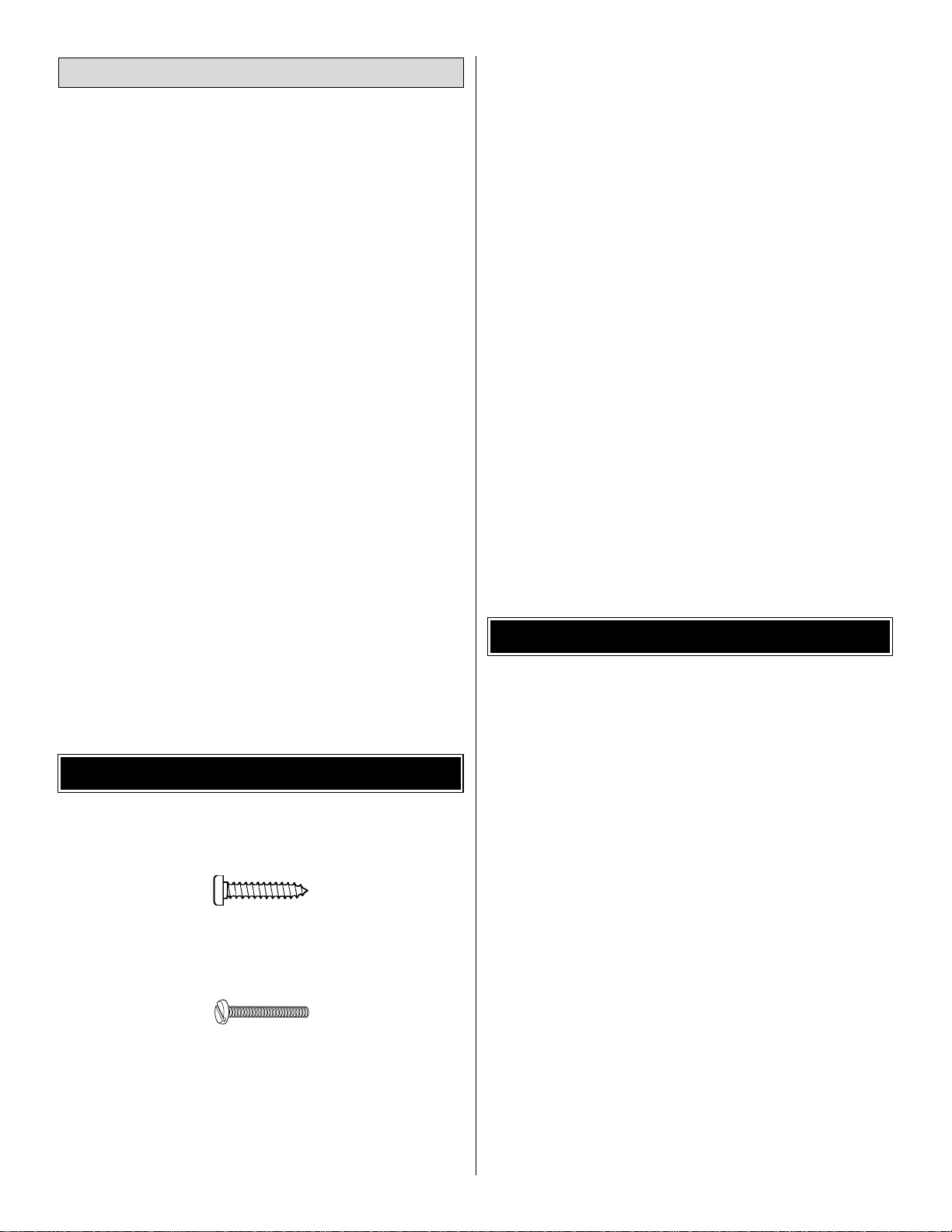
• There are two types of screws used in this kit:
Sheet metal screws are designated by a number and
a length.
For example #6 x 3/4”[19mm]
This is a number six screw that is 3/4”[19mm] long.
Machine screws are designated by a number, threads
per inch, and a length.
For example 4-40 x 3/4”[19mm]
This is a number four screw that is 3/4”[19mm] long with
forty threads per inch
.
• When you see the term
test fit
in the instructions, it means
that you should first position the part on the assembly without
using any glue, then slightly modify or
custom fit
the part as
necessary for the best fit.
• Whenever the term
glue
is written you should rely upon
your experience to decide what type of glue to use.When
a specific type of adhesive works best for that step, the
instructions will make a recommendation.
• Whenever just
epoxy
is specified you may use
either
30minute (or 45-minute) epoxy or6-minute epoxy. When 30minute epoxy is specified it is highly recommended that
you use only 30-minute (or 45-minute) epo xy, because you
will need the working time and/or the additional strength.
• Photos and sketches are placed before the step they
refer to .Frequently you can study photos in following steps
to get another view of the same parts.
• The stabilizer and wing incidences and motor thrust angles
have been factory-built into this model. However, some
technically minded modelers may wish to check these
measurements anyway. To view this information visit the
web site at www.greatplanes.com and click on “Technical
Data.” Due to manufacturing tolerances which will have
little or no effect on the way your model will fly, please
expect slight deviations between your model and the
published values.
Fuse = Fuselage
Fin = Ver tical Fin
LE = Leading Edge
TE = Trailing Edge
LG = Landing Gear
Ply = Plywood
Stab = Horizontal Stabilizer
" = Inches
SHCS = Socket Head Cap Screw
mm = Millimeters
COMMON ABBREVIATIONS
IMPORTANT BUILDING NOTES
Optional Supplies and Tools
4
Page 5
5
Before starting to build, take an inventory of this kit to make sure it is complete, and inspect the parts to make sure they
are of acceptable quality. If any parts are missing or are not of acceptable quality, or if you need assistance with assembly,
contact Product Support. When repor ting defective or missing parts, use the part names exactly as they are written in
the Kit Contents list.
Great Planes Product Support:
3002 N Apollo Drive, Suite 1
Champaign, IL 61822
Telephone: (217) 398-8970, ext. 5
Fax: (217) 398-7721
E-mail:
airsupport@greatplanes.com
KIT INSPECTION
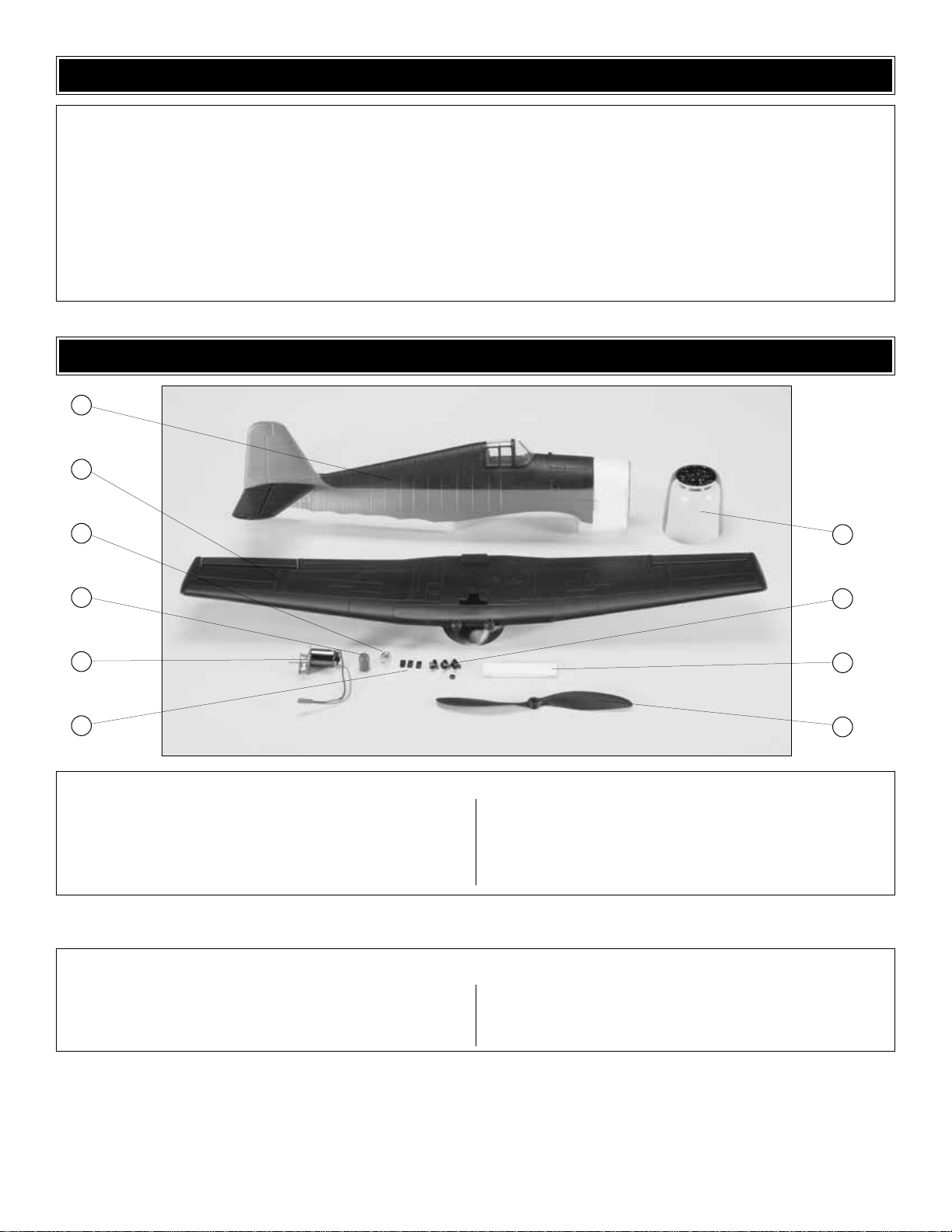
1 Fuselage
2 Wing
3 Prop Adapter
4 Nose Cone
5 Motor and Gear Drive
6 Control Hor n Keepers
7 Cowl
8 Control Hor ns
9 Hook and Loop
10 Propeller
Kit Contents (Photographed)
Control Horns (3)
Control Horn Retainers (3)
Pushrod Snap Keepers (3)
Aileron Pushrods (2)
Elevator Pushrod (1) + guide
3 x 20mm Wood Screw (1)
2x13mm Sheet Metal Screw (3)
Quick Connectors (2)
Kit Contents (Not Photographed)
KIT CONTENTS
1
2
3
4
5
6
7
8
9
10
Page 6

6
ORDERING REPLACEMENT PARTS
Replacement parts for the Great Planes Hellcat Park Flyer ARF are av ailab le using the order numbers in the Replacement
Parts List that follows.The fastest, most economical service can be provided by your hobb y dealer or mail-order compan y.
To locate a hobby dealer, visit the Hobbico web site at www.hobbico.com. Choose “Where to Buy” at the bottom of the
menu on the left side of the page.Follow the instructions provided on the page to locate a U.S., Canadian or International
dealer. If a hobby shop is not available, replacement parts may also be ordered from Tower Hobbies®at
www.towerhobbies.com, or by calling toll free (800) 637-6050.
Parts may also be ordered directly from Hobby Services by calling (217) 398-0007, or via facsimile at (217) 398-7721, but
full retail prices and shipping and handling charges will apply. Illinois and Nevada residents will also be charged sales tax.
If ordering via fax, include a Visa
®
or MasterCard®number and expiration date for payment.
Mail parts orders and payments by personal check to:
Hobby Services
3002 N Apollo Drive, Suite 1
Champaign IL 61822
Be certain to specify the order number exactly as listed in the Replacement Parts List.Payment b y credit card or personal
check only; no C.O.D.
If additional assistance is required for any reason contact Product Support by e-mail at productsupport@greatplanes.com,
or by telephone at (217) 398-8970.
REPLACEMENT PARTS LIST
ORDER NUMBER DESCRIPTION HOW TO PURCHASE
GPMA2631............................WING SET HELLCAT EP........................Hobby Supplier
GPMA2632.................FUSELAGE SET HELLCAT EP W/TAIL.............Hobby Supplier
GPMA2633...............................COWL HELLCAT EP ...........................Hobby Supplier
GPMA2634.............................CANOPY HELLCAT EP.........................Hobby Supplier
GPMA2635...........................DECAL SET HELLCAT EP ......................Hobby Supplier
GPMG0260 ...................GEAR DRIVE CORSAIR/HELLCAT................Hobby Supplier
GPMG0261 ....................MAIN GEAR CORSAIR/HELLCAT.................Hobby Supplier
GPMG0262 ...................PINION GEAR CORSAIR/HELLCAT...............Hobby Supplier
GPMG0311...........................................Motor .......................................Hobby Supplier
Missing pieces....................Contact Product Suppor t
Instruction manual.................Contact Product Support
Full-size plans .............................Not available
To convert inches to millimeters, multiply inches by 25.4
Page 7
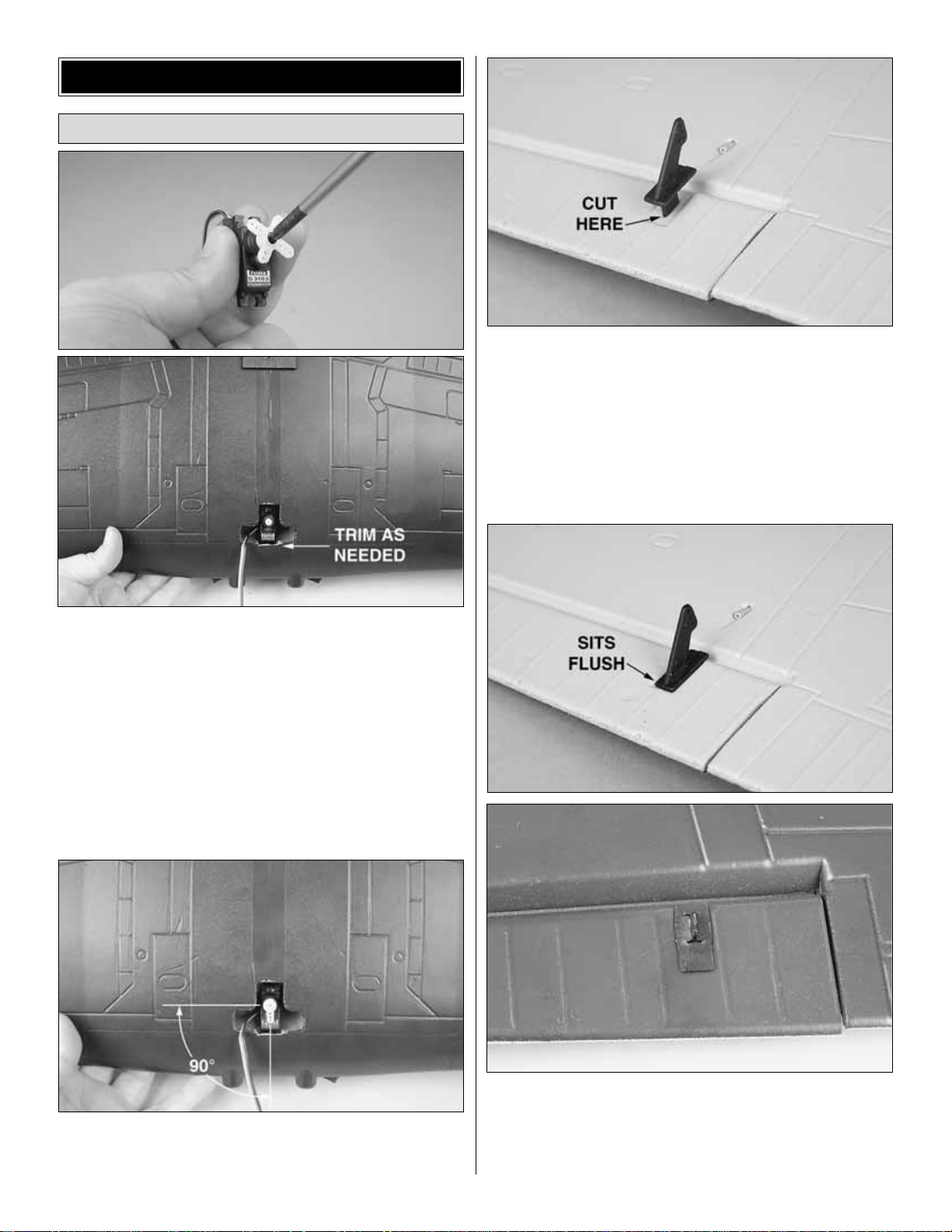
❏ 1. Remove the servo arm before inserting the aileron
servo as shown. If necessary, trim the foam slightly to allow
the servo to clear the wing opening. The servo lead should
exit the servo bay through the notch in the servo tray.
❏ 2. Glue the servo in place using thick, foam safe CA.
Epoxy may be used to glue the servo, but CA is easier to
remove should the servo need replacing in the future.
❏ 3. Temporarily connect the aileron servo to your radio
system. Be sure all sticks and trims are centered when you
turn on the radio. This will center the aileron ser vo.
❏ 4. Attach a servo arm to the servo as shown and cut off
the unused arms. The arm should point straight towards the
LE with the servo centered.
❏❏5. Locate one of the black nylon control horns.
Make a small cut through the aileron in the area marked for
the control horn.
❏❏6. Apply a drop or two of thick, foam safe CA to the
control horn and push it through the cut. The horn should sit
flush on the aileron. Press a black nylon back plate onto
the control horn as shown. Glue the back plate in place
using thin, foam safe CA.
Aileron Installation
BUILDING INSTRUCTIONS
7
Page 8

❏❏7.Locate one 14" [356mm] bent aileron pushrod wire.
Slide the wire into the pushrod guide tube located near the
control horn as shown.
❏❏8. Inser t the bent end of the pushrod into the middle
hole on the control horn. Attach a black nylon control horn
keeper to the pushrod as shown. Secure the snap keeper
to the pushrod with a drop of thin foam safe CA.
❏ 9. Repeat steps 4 through 8 for the other side of the wing.
❏ 10.Locate one of the pushrod quick connectors. Remove
the servo arm and attach the quick connector as shown. Use
a sharp hobby knife to enlarge the hole in the arm to allow the
connector to rotate freely. Add a drop of Threadlocker to the
bottom screw to prevent it from backing out.
❏ 11. Slide both aileron pushrods through the hole in the
quick connect as shown and reattach the servo arm.
❏ 12. Center both ailerons and then tighten the long screw on
the quick connector to secure the aileron pushrods.
8
Page 9

❏ 1. Remove the battery hatch from the fuselage by pulling
straight up on the tab as shown.The hatch is held in place by
a magnet.
❏ 2.Slide the elevator pushrod guide into the hole in the
rear of the fuselage as shown. Leave 1/4" [6mm] extending
out of the fuselage. Add a couple drops of thick, foam safe
CA to secure the tube in place.
❏ 3.Install the elevator servo as shown. Be sure to remove
the servo arm prior to gluing the servo in place. Install a
quick connector in the outer hole on the servo arm and
reattach it to the servo.
❏ 4. Insert the 20-3/4" [527mm] elevator pushrod wire
into the pushrod guide. When the wire enters the radio
compartment, guide it into the ser vo quick connector. Do
not tighten the quick connector yet.
❏ 5. Align the elevator control horn with the pushrod as
shown. Align the holes in the control hor n with the hinge
line. As before, cut a small slot in the elev ator and install the
control horn as shown.
Elevator Installation
9
Page 10

❏ 6. Insert the pushrod into the middle hole on the control
horn. Attach a snap keeper to the pushrod and secure it to
the pushrod with a drop of thin foam safe CA.
❏ 7. Temporarily connect the elevator servo to your radio
system and center it.
❏ 8. Center the elevator. Add a drop of Threadlocker to the
quick connect long screw and tighten it to secure
the pushrod.
❏ 9. With the elevator at neutral, glue the pushrod guide
tube to the fuselage at the point shown.
❏ 10.Trim off excess pushrod wire.
❏ 1.Locate the motor and gearbox assembly.
❏ 2. Remove the cowl and slide the motor assembly into
the firewall as shown. The motor leads route into the radio
compartment from below.
❏ 3. Using three 2 x 13mm
sheet metal screws, attach
the gearbox to the firewall.
There are holes predrilled in the
firewall as a guide. Remove the
screws and harden the holes
with thin CA. Allow the CA to
fully harden before reinstalling
the screws.
Motor Installation
10
Page 11
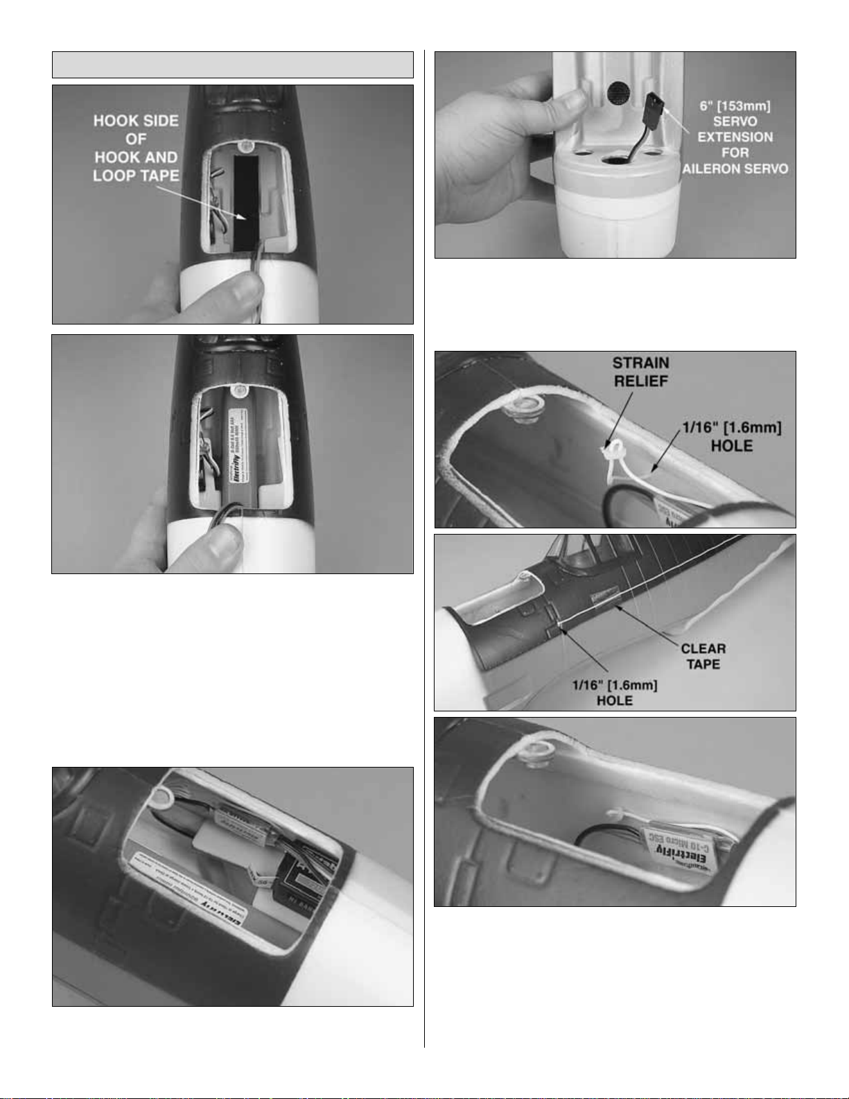
❏ 1. Attach the “Hook,” or rough side, of the supplied hook
and loop tape to the battery tray inside the radio
compartment. Attach the “loop,”or soft side, of the hook and
loop tape to the underside of the battery. Install the batter y
as shown.
❏ 2. Using leftover hook and loop tape, or double sided
servo tape, mount the receiver in the radio compartment.
❏ 3. Connect the electronic speed control (ESC) and
elevator servo to the receiver.
❏ 4.Connect a 6" [153mm] servo extension to the aileron
channel on your receiver. Route the extension below the
radio tray and out the middle hole in the leading edge of the
wing saddle as shown in the photo.
❏ 5. Drill a 1/16" [1.6mm] hole in the side of the fuse near
the receiver. The exact location is not important. Route the
antenna out of this hole and along the fuse side. Make sure
you have a strain relief on the antenna where it exits the
fuselage to keep the pressure off of the solder joints in the
receiver . Secure the antenna to the fuselage with clear tape.
❏ 6.Reinstall the batter y hatch.
Radio and Battery Installation
11
Page 12

❏ 1. Attach the cowling to the fuselage. Add a very small
drop of thin foam safe CA to each side of the fuselage where
the cowl slides on. This will help hold it on while in the air,
but also allow it to come off later for access to the motor.
❏ 2. Slide the prop and prop adapter onto the gearbox
shaft. Install the prop washer with the flange forward.
Tighten the prop adapter nut to secure it to the shaft.
❏ 3.Snap the nose cone onto the prop adapter.
❏ 1. Connect the aileron servo lead to the extension
coming from the fuselage. Slide the wing in place slowly
while feeding the wires back into the fuselage.
❏ 2. Align the wing LE with the holes in the fuselage former
and slide it into place.
❏ 3. Secure the wing to
the fuselage using the
3 x 20mm wood screw.
Do not overtighten!
Main Wing Installation
Propeller Installation
FINAL PREPARATIONS
12
Page 13

❏ 1. Use scissors or a sharp hobby knife to cut the decals
from the sheet.
❏ 2. Be cer tain the model is clean and free from finger prints,
oil and dust.Prepare a dishpan or small bucket with a mixture of
liquid dish soap and warm water—about one teaspoon of soap
per gallon of water.Submerse the decal in the soap and water
and peel off the paper backing.
Note: Even though the decals have a “sticky-back” and are not
the water transfer type , submersing them in soap & water allows
accurate positioning and reduces air bubbles underneath.
❏ 3. Position decal on the model where desired. Holding the
decal down, use a paper towel to wipe most of the water away.
❏ 4. Use a piece of soft balsa or something similar to squeegee
remaining water from under the decal. Apply the rest of the
decals the same way.
❏ 1. Tur n on the transmitter and receiver and center the
trims. If necessary, remove the servo arms from the servos
and reposition them so they are centered. Reinstall the
screws that hold on the servo arms.
❏ 2. With the transmitter and receiver still on, check all the
control surfaces to see if they are centered.If necessary, adjust
the clevises on the pushrods to center the control surfaces.
❏ 3. Make certain that the control surfaces and the throttle
respond in the correct direction as shown in the diagram.If any
of the controls respond in the wrong direction, use the servo
reversing in the transmitter to reverse the servos connected to
those controls. Be cer tain the control surfaces have remained
centered. Adjust if necessary.
Use a Great Planes AccuThrow™(or a ruler) to accurately
measure and set the control throw of each control surface as
indicated in the chart that follows.If your radio does not hav e
dual rates, we recommend setting the throws at the low
rate setting.
NOTE:The throws are measured at the widest part of the
elevators and ailerons.
These are the recommended control surface throws:
At this stage the model should be in ready-to-fly condition
with all of the systems in place including the motor, battery
and the radio system.
More than any other factor, the C.G. (balance point) can
have the greatest effect on how a model flies, and may
determine whether or not your first flight will be
successful. If you value this model and wish to enjoy it for
many flights, DO NOT OVERLOOK THIS IMPORTANT
PROCEDURE. A model that is not properly balanced will
be unstable and possibly unflyable.
Balance the Model CG
IMPORTANT: The Great Planes Hellcat Park Flyer ARF
has been extensively flown and tested to arrive at the
throws at which it flies best. Flying your model at these
throws will provide you with the greatest chance for
successful first flights. If, after you have become
accustomed to the way the Great Planes Hellcat Park
Flyer ARF flies, you would lik e to change the throws to suit
your taste, that is fine. However, too much control throw
could make the model difficult to control, so remember,
“More is not always better.”
High Rate Low Rate
ELEVATOR 3/8" [10mm] up 3/16" [5mm] up
3/8" [10mm] down 3/16" [5mm] down
AILERONS 3/8" [10mm] up 1/4" [6mm] up
5/16" [8mm] down 1/8" [3mm] down
Set the Control Throws
4-CHANNEL
TRANSMITTER
TRANSMITTER
4-CHANNEL
TRANSMITTER
4-CHANNEL
MOTOR FULL THROTTLE
Check the Control Directions
GET THE MODEL READY TO FLY
Apply the Decals
13
Page 14

❏ 1. Use a felt-tip pen or 1/8" [3mm]-wide tape to accurately
mark the C.G. on the top of the wing on both sides of the
fuselage. The C.G. is located 2" [51mm] back from the
leading edge of the wing at the root.
❏ 2. With the wing attached to the fuselage and all parts of
the model installed (ready to fly), place the model upsidedown on a Great Planes CG Machine, or lift it upside-down
at the balance point you marked.
❏ 3. If the tail drops, the model is “tail heavy” and the
battery pack and/or receiver must be shifted forward or
weight must be added to the nose to balance. If the nose
drops, the model is “nose heavy” and the battery pack
and/or receiver must be shifted aft or weight must be added
to the tail to balance. If possible, relocate the battery pack
and receiver to minimize or eliminate any additional ballast
required. If additional weight is required, nose weight may
be easily added by using Great Planes (GPMQ4485)
“stick-on” lead. A good place to add stick-on nose weight is
to the firewall (don’t attach weight to the cowl—it is not
intended to support weight). Begin by placing incrementally
increasing amounts of weight on the bottom of the fuse over
the firewall until the model balances. Once you have
determined the amount of weight required, it can be
permanently attached.
IMPORTANT: If you found it necessary to add any weight,
recheck the C.G.after the weight has been installed.
❏ 1.With the wing level, have an assistant help you lift the
model by the motor propeller shaft and the bottom of the
fuse under the TE of the fin.Do this several times.
❏ 2. If one wing always drops when you lift the model, it means
that side is heavy. Balance the airplane by adding weight to the
other wing tip. An airplane that has been laterally balanced
will track better in loops and other maneuvers.
No matter if you fly at an AMA sanctioned R/C club site or if
you fly somewhere on your own, you should always have
your name, address, telephone number and AMA number
on or inside your model. It is required at all AMA R/C club
flying sites and AMA sanctioned flying events.
Follow the battery charging instructions that came with your
radio control system to charge the batteries. You should
always charge your transmitter and airplane batteries the
night before you go flying, and at other times as
recommended by the radio manufacturer.
Carefully balance your propeller and spare propellers before
you fly. An unbalanced prop can be the single most significant
cause of vibration that can damage your model.Vibration may
also damage your radio receiver and battery. We use a Top
Flite Precision Magnetic Prop Balancer™(TOPQ5700) in the
workshop and keep a Great Planes Fingertip Prop Balancer
(GPMQ5000) in our flight box.
Balance Propellers
CAUTION: Unless the instructions that came with your
radio system state differently, the initial charge on new
transmitter and receiver batteries should be done for 15
hours using the slow-charger that came with the radio
system.This will “condition” the batteries so that the next
charge may be done using the fast-charger of your
choice. If the initial charge is done with a fast-charger the
batteries may not reach their full capacity and you may be
flying with batteries that are only partially charged.
Charge the Batteries
Identify your Model
PREFLIGHT
Balance the Model Laterally
This is where your model should balance for the first
flights. Later, you may wish to experiment by shifting the
C.G. up to 1/4" [6.4mm] forward or 1/4" [6.4mm] back to
change the flying characteristics.Moving the C.G.forward
may improve the smoothness and stability, but the model
may then require more speed for tak eoff and make it more
difficult to slow for landing.Moving the C.G.aft makes the
model more maneuverable, but could also cause it to
become too difficult to control. In any case, start at the
recommended balance point and do not at any time
balance the model outside the specified range.
14
Page 15

Ground check the operational range of your r adio before the
first flight of the day. With the transmitter antenna collapsed
and the receiver and transmitter on, you should be able to
walk at least 100 feet away from the model and still have
control. Have an assistant stand by your model and, while
you work the controls, tell you what the control surfaces are
doing. Repeat this test with the motor running at various
speeds with an assistant holding the model, using hand
signals to show you what is happening. If the control
surfaces do not respond correctly, do not fly! Find and
correct the problem first. Look for loose servo connections
or broken wires, corroded wires on old servo connectors,
poor solder joints in your battery pack or a defective cell, or
a damaged receiver crystal from a previous crash.
Get help from an experienced pilot when learning to operate
electric motors.
Use safety glasses when starting or running motors.
Do not run the motor in an area of loose gravel or sand;the
propeller may throw such material in your face or eyes.
Keep your f ace and body as well as all spectators aw ay from the
plane of rotation of the propeller as you start and run the motor.
Keep these items away from the prop: loose clothing, shir t
sleeves, ties, scarfs, long hair or loose objects such as
pencils or screwdrivers that may fall out of shirt or jacket
pockets into the prop.
The motor gets hot! Do not touch it during or right
after operation.
Do not use hands, fingers or any other body part to try to
stop the motor.Do not throw anything into the propeller of a
running motor.
Read and abide by the following e xcerpts from the Academy
of Model Aeronautics Safety Code.For the complete Safety
Code refer to
Model Aviation
magazine, the AMA web site
or the Code that came with your AMA license.
GENERAL
1) I will not fly my model aircraft in sanctioned events, air
shows, or model flying demonstrations until it has been
proven to be airworthy by having been previously,
successfully flight tested.
2) I will not fly my model aircraft higher than approximately
400 feet within 3 miles of an airport without notifying the
airport operator. I will give right-of-way and avoid flying in
the proximity of full-scale aircraft. Where necessary, an
observer shall be utilized to supervise flying to avoid having
models fly in the proximity of full-scale aircraft.
3) Where established, I will abide by the safety rules for the
flying site I use, and I will not willfully and deliberately fly my
models in a careless, reckless and/or dangerous manner.
5) I will not fly my model unless it is identified with my name
and address or AMA number, on or in the model.Note:This
does not apply to models while being flown indoors.
7) I will not operate models with pyrotechnics (any device
that explodes, burns, or propels a projectile of any kind).
RADIO CONTROL
1) I will have completed a successful radio equipment ground
check before the first flight of a new or repaired model.
2) I will not fly my model aircraft in the presence of
spectators until I become a qualified flyer, unless assisted
by an experienced helper.
3) At all flying sites a straight or curved line(s) must be
established in front of which all flying takes place with the
other side for spectators.Only personnel involved with flying
the aircraft are allowed at or in the front of the flight line.
Intentional flying behind the flight line is prohibited.
4) I will operate my model using only radio control
frequencies currently allowed by the Federal
Communications Commission.
5) I will not knowingly operate my model within three
miles of any pre-existing flying site except in
accordance with the frequency sharing agreement
listed [in the complete AMA Safety Code].
9) Under no circumstances may a pilot or other person
touch a powered model in flight;nor should any part of the
model other than the landing gear, intentionally touch
the ground, except while landing.
❏ 1. Check the C.G. according to the measurements
provided in the manual.
❏ 2. Be certain the battery and receiver are securely
mounted in the fuse. Simply stuffing them into place
with foam rubber is not sufficient.
❏ 3. Extend your receiver antenna and make sure it has a
strain relief inside the fuselage to keep tension off the
solder joint inside the receiver.
❏ 4. Balance your model
laterally
as explained in the instructions.
During the last few moments of preparation your mind ma y be
elsewhere anticipating the excitement of the first flight.
Because of this, you may be more likely to overlook certain
checks and procedures that should be performed before the
model is flown.To help avoid this, a check list is provided to
make sure these important areas are not overlooked. Many
are covered in the instruction manual, so where appropriate,
refer to the manual f or complete instructions.Be sure to check
the items off as they are completed.
CHECK LIST
AMA SAFETY CODE (
EXCERPTS
)
Failure to follow these safety precautions may result
in severe injury to yourself and others.
MOTOR SAFETY PRECAUTIONS
Range Check
15
Page 16

❏ 5. Use threadlocking compound to secure critical fasteners
such as quick connect pushrod connectors, etc.
❏ 6. Reinforce holes for wood screws with thin CA where
appropriate (gearbox mounting screws, etc.).
❏ 7. Confirm that all controls operate in the correct direction
and the throws are set up according to the manual.
❏ 8. Make sure that all servo arms are secured to the
servos with the screws included with your radio.
❏ 9.Make sure any servo extension cords you may have
used do not interfere with other systems (servo arms,
pushrods, etc.).
❏ 10. Balance your propeller (and spare propellers).
❏ 11. Tighten the propeller nut and ensure the nose cone
is securely attached.
❏ 12. Place your name, address, AMA number and
telephone number on or inside your model.
❏ 13. Cycle your battery pack (if necessary) and make
sure it is fully charged.
❏ 14. If you wish to photograph your model, do so before
your first flight.
❏ 15. Range check your radio when y ou get to the flying field.
The Great Planes Hellcat is a great-flying model that flies
smoothly and predictably. The Great Planes Hellcat does not,
howev er, possess the self-recov ery characteristics of a primary
R/C trainer and should be flown only by e xperienced R/C pilots.
For the first flight, it is a good idea to have an assistant launch
the airplane for you. This allows you to k eep your hands on the
controls and correct any trim problems that become apparent.
Have your assistant hold the bottom of the fuse just behind the
wing. Throttle up to full power and have your assistant give the
Hellcat a firm, but not hard, toss straight ahead. Apply a small
amount of up elevator and gently climb out to a comfortable
altitude. Be careful not to climb too f ast as you will lose airspeed
and the Hellcat may stall.
For reassurance and to keep an eye on other traffic, it is a
good idea to have an assistant on the flight line with you.Tell
him to remind you to throttle back once the plane gets to a
comfortable altitude.While full throttle is usually desirable for
takeoff, most models fly more smoothly at reduced speeds.
T ak e it easy with the Great Planes Hellcat for the first f ew flights,
gradually getting acquainted with it as you gain confidence.
Adjust the trims to maintain straight and level flight. After flying
around for a while, and while still at a saf e altitude with plenty of
battery power remaining, practice slow flight and execute
practice landing approaches by reducing the throttle to see how
the model handles at slower speeds.Add power to see how the
Hellcat climbs as well.Continue to fly around, executing v arious
maneuvers and making mental notes (or having your assistant
write them down) of what trim or C.G.changes may be required
to fine tune the model so it flies the way you like. Mind your
battery power, but use this first flight to become f amiliar with your
model before landing.
Because this model is very lightweight, it does not retain energy
well. Performing a nice, gentle, gliding landing may be difficult.
Instead, we recommend landing the Hellcat under power. You
will want to bring the Hellcat in at reduced throttle, modulating
your descent using the throttle. When you are just above the
deck, use a quick “blip”on the power to flare the Hellcat and rest
it gently on its belly.
One final note about flying your model.Have a goal or flight plan
in mind for every flight.This can be learning a new maneuv er(s),
improving a maneuver(s) you already kno w , or learning how the
model behaves in certain conditions (such as on high or low
rates).This is not necessarily to improve your skills (
though it is
never a bad idea!)
, but more importantly so you do not surprise
yourself by impulsively attempting a maneuver and suddenly
finding that you’ve run out of time, altitude or airspeed. Every
maneuver should be deliberate, not impulsive. For example, if
you’re going to do a loop, check your altitude, mind the wind
direction (anticipating rudder corrections that will be required to
maintain heading), remember to throttle back at the top, and
make certain you are on the desired rates (high/low rates). A
flight plan greatly reduces the chances of crashing your model
just because of poor planning and impulsive moves.
Remember to think.
Have a ball! But always sta y in control and fly in a safe manner .
Landing
Flight
Hand Launch
CAUTION (THIS APPLIES TO ALL
R/C AIRPLANES): If,
while flying, you notice an alarming or unusual sound such
as a low-pitched “buzz,” this may indicate control surface
flutter.
Flutter occurs when a control surface (such as an
aileron or elevator) or a flying surface (such as a wing or
stab) rapidly vibrates up and down (thus causing the noise).
In extreme cases, if not detected immediately, flutter can
actually cause the control surface to detach or the flying
surface to fail, thus causing loss of control followed by an
impending crash. The best thing to do when flutter is
detected is to slow the model immediately by reducing
power, then land as soon as safely possible. Identify which
surface fluttered (so the problem may be resolved) by
checking all the servo grommets for deterioration or signs
of vibration. Make cer tain all pushrod linkages are secure
and free of play. If it fluttered once, under similar
circumstances it will probably flutter again unless the
problem is fixed. Some things which can cause flutter are;
Excessive hinge gap; Not mounting control horns solidly;
Poor fit of clevis pin in horn; Side-play of wire pushrods
caused by large bends;Excessive free play in servo gears;
Insecure servo mounting; and one of the most prevalent
causes of flutter; Flying an over-powered model at
excessive speeds.
FLYING
 Loading...