

Page 1

WARRANTY
Great Planes
®
Model Manufacturing Co. guarantees this kit to be free from defects in both material and workmanship at the date of
purchase.This warranty does not cover any component parts damaged by use or modification. In no case shall Great Planes’ liability
exceed the original cost of the purchased kit. Further, Great Planes reserves the right to change or modify this warranty without notice.
In that Great Planes has no control over the final assembly or material used for final assembly, no liability shall be assumed nor
accepted for any damage resulting from the use by the user of the final user-assemb led product.By the act of using the user-assembled
product, the user accepts all resulting liability.
If the buyer is not prepared to accept the liability associated with the use of this product, the buyer is advised to return this
kit immediately in new and unused condition to the place of purchase.
To make a warranty claim send the defective part or item to Hobby Services at the address below:
Hobby Services
3002 N. Apollo Dr. Suite 1
Champaign IL 61822 USA
Include a letter stating your name, return shipping address, as much contact information as possible (daytime telephone number, fax
number, e-mail address), a detailed description of the problem and a photocopy of the purchase receipt. Upon receipt of the package
the problem will be evaluated as quickly as possible.
READ THROUGH THIS MANUAL BEFORE STARTING
CONSTRUCTION. IT CONTAINS IMPORTANT WARNINGS
AND INSTRUCTIONS CONCERNING THE ASSEMBLY
AND USE OF THIS MODEL.
GPMZ0200 for GPMA1156 V1.0© Copyright 2004
Champaign, Illinois
(217) 398-8970, Ext 5
airsupport@greatplanes.com
INSTRUCTION MANUAL
Wingspan: 39.5 in [1000mm]
Wing Area: 276 sq in [17.8 dm2]
Weight: 22-24 oz [620-680 g]
Wing Loading: 11-13 oz/sq ft [34-40 g/dm2]
Length: 30 in [760mm]
Radio: 4-channel with three micro servos (not included)
Motor: 400 size
Electronic Speed Control: Electrifly C-20 (not included)
Page 2
INTRODUCTION................................................................2
SAFETY PRECAUTIONS..................................................3
DECISIONS YOU MUST MAKE ........................................3
Battery Charger Options..............................................3
Connector Replacement..............................................3
ADDITIONAL ITEMS REQUIRED.....................................4
Hardware and Accessories ..........................................4
Adhesives and Building Supplies.................................4
Optional Supplies and Tools ........................................4
IMPORTANT BUILDING NOTES.......................................4
COMMON ABBREVIATIONS............................................4
KIT INSPECTION...............................................................5
KIT CONTENTS .................................................................5
ORDERING REPLACEMENT PARTS...............................6
PREPARATIONS................................................................7
ASSEMBLE THE WING.....................................................7
Install the Ailerons .......................................................7
Join the Wing Halves...................................................7
ASSEMBLE THE FUSELAGE...........................................8
Mount the Wing............................................................8
Mount the Stabilizer and Fin ........................................8
MOUNT THE MOT OR......................................................10
RADIO INSTALLATION...................................................11
Install the Control Horns............................................11
Install the Servos.......................................................12
MOUNT THE LANDING GEAR.......................................14
FINISH THE MODEL........................................................15
Mount the Canopy .....................................................15
Mount the Battery ......................................................15
Apply the Decals ........................................................16
GET THE MODEL READY TO FLY..................................16
Check the Control Directions.....................................16
Set the Control Throws..............................................17
Mount the Propeller ...................................................17
Balance the Model (C.G.)..........................................18
Balance the Model Laterally......................................18
PREFLIGHT.....................................................................18
Identify Your Model.....................................................18
Charge the Batteries ..................................................18
Balance Propellers.....................................................19
PROPER CARE OF YOUR MOTOR ................................19
PERFORMANCE TIPS.....................................................19
Ground Check............................................................19
Range Check.............................................................19
MOTOR SAFETY PRECAUTIONS..................................20
AMA SAFETY CODE ......................................................20
CHECK LIST ....................................................................20
FLYING.............................................................................21
Takeoff .......................................................................21
Flight..........................................................................21
Landing......................................................................21
The Great Planes Super Sportster has been a favorite
among pilots since1984.For many pilots the Super Sportster
was their first low-wing plane. Now, Great planes brings you
the Super Sportster tradition in an electric park flyer version.
Following the lines of the Super Sportster, the Mini Super
Sportster EP has been lightened to accommodate electric
power without sacrificing performance. If you’re ready to
continue the Super Sportster tradition without the fuss and
mess of a glow engine, the Mini Super Sportster EP is just
what you need.
For the latest technical updates or manual corrections to the
Mini Super Sportster EP visit the Great Planes web site at
www.g reatplanes.com.Open the “Airplanes” link, then select
the Mini Super Sportster EP. If there is new technical
information or changes to this model a “tech notice” box will
appear in the upper left corner of the page.
We urge you to join the AMA (Academy of Model Aeronautics)
and a local R/C club.The AMA is the governing body of model
aviation and membership is required to fly at AMA clubs.
Though joining the AMA provides many benefits, one of the
primary reasons to join is liability protection. Coverage is not
limited to flying at contests or on the club field. It even applies
to flying at public demonstrations and air shows. Failure to
comply with the Safety Code (excerpts printed in the back of
the manual) may endanger insurance coverage. Additionally,
training programs and instructors are available at AMA club
sites to help you get started the right way. There are over
2,500 AMA chartered clubs across the countr y. Contact the
AMA at the address or toll-free phone number below:
Academy of Model Aeronautics
5151 East Memorial Drive
Muncie, IN 47302-9252
Tele.(800) 435-9262
Fax (765) 741-0057
Or via the Internet at:
http://www.modelaircraft.org
IMPORTANT!!! Two of the most important things you can do
to preserve the radio controlled aircraft hobby are to avoid
flying near full-scale aircraft and avoid flying near or over
groups of people.
AMA
INTRODUCTIONTABLE OF CONTENTS
2
Page 3

1.Your Mini Super Sportster EP should not be considered a
toy, but rather a sophisticated, working model that functions
very much like a full-size airplane.Because of its performance
capabilities, the Mini Super Sportster EP ARF, if not
assembled and operated correctly, could possibly cause
injury to yourself or spectators and damage to property.
2. You must assemble the model according to the
instructions. Do not alter or modify the model, as doing so
may result in an unsafe or unflyable model. In a few cases
the instructions may differ slightly from the photos.In those
instances the written instructions should be considered
as correct.
3.You must take time to build straight, true and strong.
4. You must use an R/C radio system that is in firstclass condition.
5.You must correctly install all R/C and other components so
that the model operates correctly on the ground and in the air.
6.You must check the operation of the model before every
flight to insure that all equipment is operating and that the
model has remained structurally sound. Be sure to check
clevises or other connectors often and replace them if they
show any signs of wear or fatigue.
7. If you are not an experienced pilot or have not flown this
type of model before, we recommend that you get the
assistance of an experienced pilot in your R/C club for your
first flights.If you’re not a member of a club, your local hobb y
shop has information about clubs in your area whose
membership includes experienced pilots.
8. WARNING: The wheel pants included in this kit are made
of fiberglass, the fibers of which may cause eye, skin and
respiratory tract irritation.Never blow into a part (wheel pant)
to remove fiberglass dust, as the dust will blow back into
your eyes. Always wear safety goggles, a particle mask and
rubber gloves when grinding, drilling and sanding fiberglass
parts. Vacuum the parts and the work area thoroughly after
working with fiberglass parts.
Remember:Take y our time and f ollo w the instructions to
end up with a well-built model that is straight and true.
A fully charged battery pack will provide an initial “surge” of
power during the first 15 to 30 seconds of the motor run.
Then the power output stays f airly steady for the ne xt se ver al
minutes before dropping off quickly. If you do not “peakcharge” your battery, it will not deliver that initial surge
necessary for a good takeoff and climb-out.There are three
easy ways to peak-charge your battery pack.
1. The easiest way is with a “peak-detecting” battery charger.
This type of charger will charge your battery until it is fully
charged, then automatically shut off. Using a peak-detecting
charger reduces the chances of damaging the batteries from
over-charging. We recommend the Great Planes Triton™DC
Peak Charger (GPMM3150) to keep your batteries in good
condition or the ElectriFly Peak 400 (GPMM3001).
2.The second method of charging your motor batteries is to
monitor the voltage of your battery pack with a voltmeter
while charging. This method is only recommended for
NiCd batteries. Your charger may have sockets into which
you may plug a voltmeter. If not, you may insert the probes
from the voltmeter into the rear of the battery plug, making
contact with the metal contacts.As your battery charges, the
voltage will gradually increase. When the battery is fully
charged, the voltage will start to drop. At this point your
battery is fully charged. We recommend the Hobbico®905
AC/DC Multi-Charger (HCAP0150).
3. The third (and least reliable) method of peak-charging
your battery pack is by checking its temperature. This
method is only recommended for NiCd batteries. As the
battery charges it will remain cool until it is fully charged.
When it reaches the fully charged state, it will rapidly build
up heat. You can feel this heat with your hand. As soon as
the pack starts to noticeably warm up, disconnect it from the
charger. Do not continue charging if the battery pack is
hot! Overcharging will damage your battery pack and can
result in an explosion.
The Mini Super Sportster EP comes with a BEC type
connector to allow you to change the connector on the
electronic speed control, if needed, to match the connector
supplied on the motor battery, or you may also prefer to use
the connectors of your choice. The one requirement of the
connectors is they must be able to handle a current of at
least 12 Amps.Changing the connectors will require that the
connectors be soldered to the wires from the ESC and the
battery .If you do not have soldering experience, find a fellow
modeler who does and have them help with the soldering.
Connector Replacement
Battery Charger Options
DECISIONS YOU MUST MAKE
We, as the kit manuf acturer, provide y ou with a top quality,
thoroughly tested kit and instructions, but ultimately the
quality and flyability of your finished model depends on
how you build it; therefore, we cannot in any way
guarantee the performance of your completed model, and
no representations are expressed or implied as to the
performance or safety of your completed model.
PRO TECT YOUR MODEL,Y OURSELF
& OTHERS...FOLLOW THESE
IMPORTANT SAFETY PRECAUTIONS
3
Page 4
In addition to the items listed in the “Battery Charger
Options” section, following is the list of hardware and
accessories required to finish the Mini Super Sportster EP.
Order numbers are provided in parentheses.
❏ 4-channel radio w/3 micro servos (Futaba
®
S3107, FUTM0025)
❏ ElectriFly
™
C-20 speed control (GPMM2020)
❏ 6" [150mm] ser vo extension (HCAM2701 for Futaba)
❏ 1100 mAh 9.6 volt battery (GPMP0251)
In addition to common household tools and hobby tools, this
is the “short list”of the most important items required to build
the Mini Super Sportster EP.
Great Planes Pro™CA and
Epoxy glue are recommended.
❏ 1/2 oz. [15g] Thin Pro CA (GPMR6001)
❏ Pro 30-minute epoxy (GPMR6047)
❏ Drill bits: 1/32" [.8mm], 1/16" [1.6mm], 5/64" [2mm],
7/64" [3mm]
❏ #1 hobby knife (HCAR0105)
❏ #11 blades (5-pack, HCAR0211)
❏ Medium T-pins (100, HCAR5150)
❏ Builder’s triangle set (HCAR0480)
❏ 36" metal ruler (HCAR0475)
❏ Denatured alcohol (for epoxy clean up)
Here is a list of optional tools mentioned in the manual that
will help you build the Mini Super Sportster EP.
❏ Pro
™
6-minute epoxy (GPMR6045)
❏ Stick-on segmented lead weights (GPMQ4485)
❏ Top Flite
®
MonoKote®sealing iron (TOPR2100)
❏ Top Flite Hot Sock
™
iron cover (TOPR2175)
❏ Top Flite MonoKote heat gun (TOPR2000)
❏ 2 oz. [57g] spray CA activator (GPMR6035)
❏ CA applicator tips (HCAR3780)
❏ CA debonder (GPMR6039)
❏ Epoxy brushes (6, GPMR8060)
❏ Mixing sticks (50, GPMR8055)
❏ Mixing cups (GPMR8056)
❏ Cur ved-tip canopy scissors for trimming plastic
parts (HCAR0667)
❏ Robar t Super Stand II (ROBP1402)
❏ Masking tape (TOPR8018)
❏ K & S #801 Kevlar thread (for stab alignment)
❏ CG Machine
™
(GPMR2400)
❏ Precision Magnetic Prop Balancer
™
(TOPQ5700)
❏ AccuThrow
™
Deflection Gauge (GPMR2405)
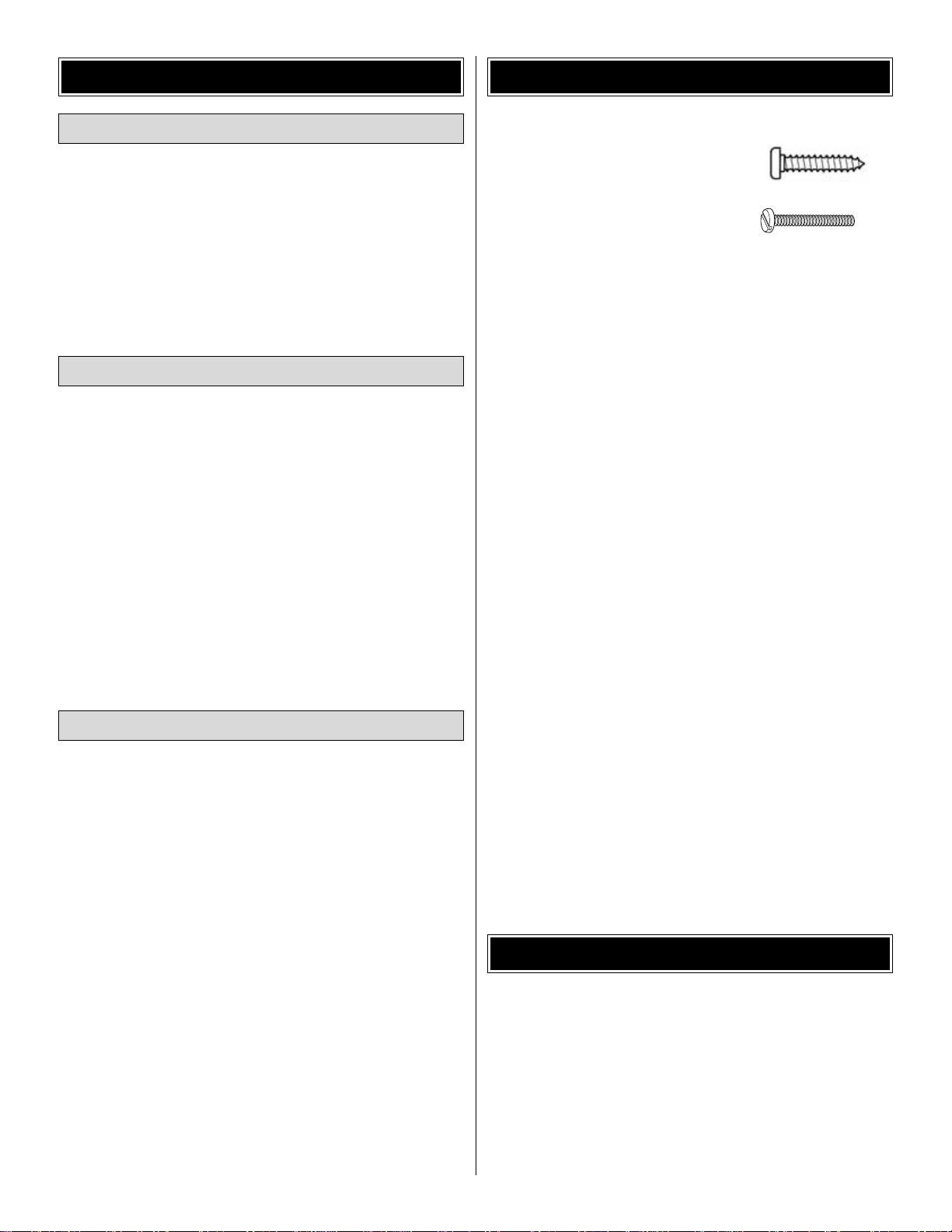
• There are two types of screws used in this kit:
Sheet metal screws are pointed
and have a coarse thread.
Machine screws have a squared
off end and a fine thread.
Both screws are designated by a number , the diameter, and
the length. For example, a 3 x 8mm screw has a diameter
of 3mm and a length of 8mm.
• When you see the term
test fit
in the instructions, it means
that you should first position the part on the assembly
without using any glue, then slightly modify or
custom fit
the part as necessar y for the best fit.
• Whenever the term
glue
is written you should rely upon
your experience to decide what type of glue to use.When
a specific type of adhesive works best for that step, the
instructions will make a recommendation.
• Whenever just
epoxy
is specified you may use
either
30-minute (or 45-minute) epoxy or6-minute epoxy. When
30-minute epoxy is specified it is highly recommended that
you use only 30-minute (or 45-minute) epoxy, because you
will need the working time and/or the additional strength.
• Photos and sketches are placed before the step they
refer to .Frequently you can study photos in following steps
to get another view of the same parts.
• The stabilizer and wing incidences and motor thrust angles
have been factory-built into this model. However, some
technically-minded modelers may wish to check these
measurements anyway.To view this information visit the web
site at www.greatplanes.com and click on “Technical Data.”
Due to manufacturing tolerances which will have little or no
effect on the way your model will fly, please expect slight
deviations between your model and the published values.
Fuse = Fuselage
Stab = Horizontal Stabilizer
Fin = Vertical Fin
LE = Leading Edge
TE = Trailing Edge
LG = Landing Gear
Ply = Plywood
" = Inches
mm = Millimeters
SHCS = Socket Head Cap Screw
COMMON ABBREVIATIONS
IMPORTANT BUILDING NOTES
Optional Supplies and Tools
Adhesives and Building Supplies
Hardware and Accessories
ADDITIONAL ITEMS REQUIRED
4
Page 5
5
Before starting to build, take an inventory of this kit to make sure it is complete, and inspect the parts to make sure they
are of acceptable quality.If any parts are missing or are not of acceptable quality, or if y ou need assistance with assemb ly,
contact Product Support. When repor ting defective or missing parts, use the part names exactly as they are written in
the Kit Contents list.
Great Planes Product Support:
3002 N Apollo Drive, Suite 1
Champaign, IL 61822
Telephone: (217) 398-8970, ext. 5
Fax: (217) 398-7721
E-mail:
airsupport@greatplanes.com
KIT INSPECTION
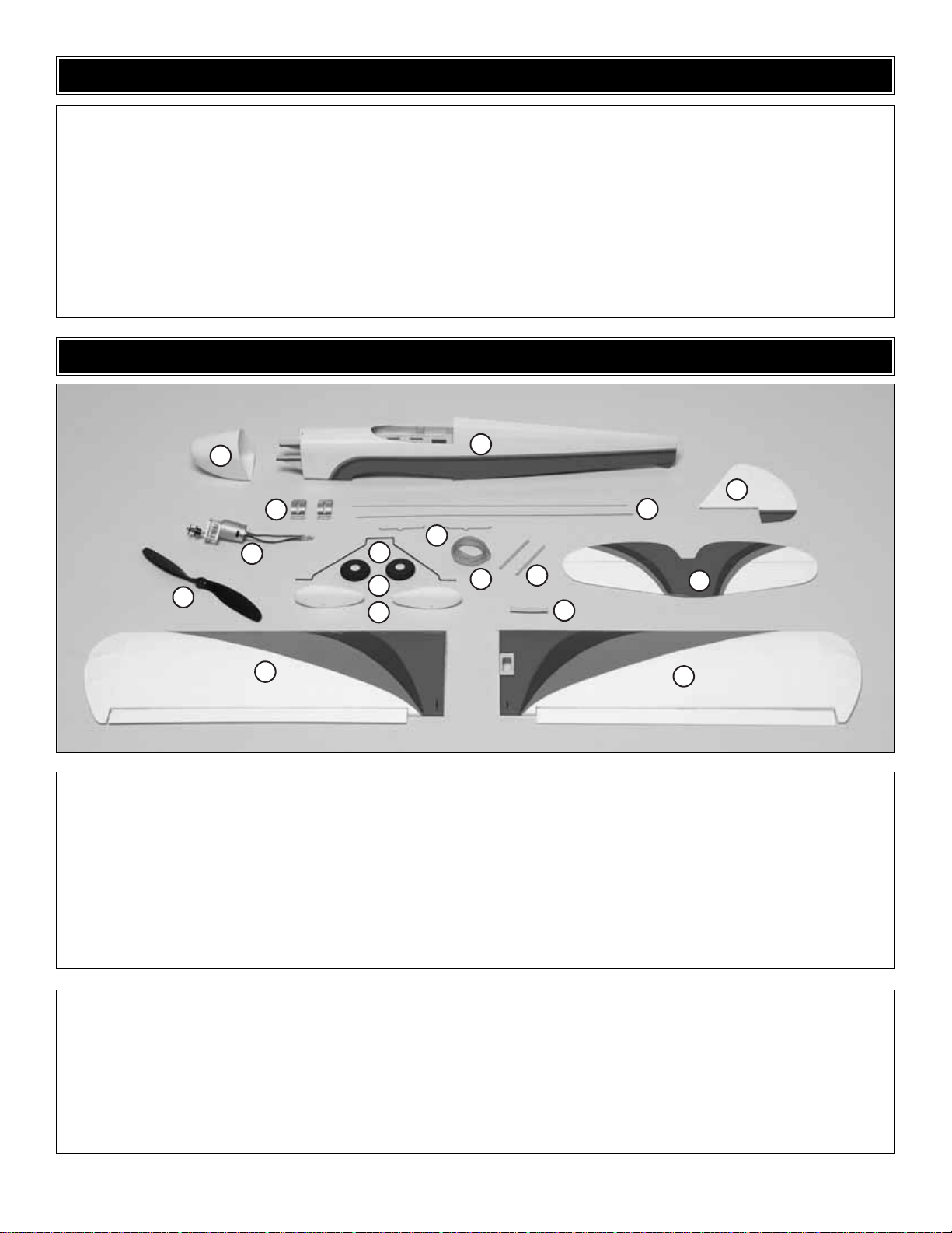
1 Fuselage
2 Left Wing Panel
3 Right Wing Panel
4 Stabilizer and Elevator
5 Fin and Rudder
6 Wheel Pants (2)
7 Wing Joiner
8 Wheels (2)
9 Main Landing Gear
10 Propeller
11 Motor and Gear Dr ive
12 Motor Mount (2)
13 Rudder and Elevator Pushrods
14 Aileron Pushrods (2)
15 Rubber Bands (4)
16 Wing Dowels (2)
17 Cowl
Kit Contents (Photographed)
Control Horns (2)
Landing Gear Strap (2)
2x4mm Sheet Metal Screw (4)
2.3x12mm Tube (1)
Hook & Loop Material (1)
Female Bullet Connector (2)
2x7mm Sheet Metal Screw (9)
CA Hinges (9)
2x9mm Machine Screw (4)
Pushrod Connector (2)
2mm Washer (2)
2mm Nut (2)
3mm Set Screw (2)
Torque Rod Horns (2)
Kit Contents (Not Photographed)
KIT CONTENTS
17
10
11
1
5
12
14
9
8
6
2
15
16
7
13
4
3
Page 6
6
ORDERING REPLACEMENT PARTS
Replacement parts for the Great Planes Mini Super Sportster EP ARF are available using the order numbers in the Replacement
Parts List that follows.The fastest, most economical service can be provided by your hobby dealer or mail-order company.
To locate a hobby dealer, visit the Great Planes web site at www.greatplanes.com. Choose “Where to Buy”at the bottom of the
menu on the left side of the page.Follow the instructions provided on the page to locate a U.S., Canadian or International dealer .
If a hobby shop is not available, replacement parts may also be ordered from Tower Hobbies at www.towerhobbies.com, or by
calling toll free (800) 637-6050.
Parts may also be ordered directly from Hobby Services by calling (217) 398-0007, or via facsimile at (217) 398-7721, but
full retail prices and shipping and handling charges will apply. Illinois and Nevada residents will also be charged sales tax.
If ordering via fax, include a Visa
®
or MasterCard®number and expiration date for payment.
Mail parts orders and payments by personal check to:
Hobby Services
3002 N Apollo Drive, Suite 1
Champaign IL 61822
Be certain to specify the order number exactly as listed in the Replacement Parts List.Payment b y credit card or personal
check only; no C.O.D.
If additional assistance is required for any reason contact Product Support by e-mail at productsupport@greatplanes.com,
or by telephone at (217) 398-8970.
Replacement Parts List
Or
der Number Description Ho
w to Purchase
Missing pieces ................................................Contact Product Support
Instruction manual...........................................Contact Product Support
Full-size plans.................................................Not available
Kit parts listed below .......................................Hobby Supplier
GPMA2765............Wing Kit
GPMA2766............Fuse Kit
GPMA2767............Tail Set
GPMA2768............Cowl
GPMA2769............Canopy
GPMA2770............Landing Gear
GPMA2771............Wheel Pants
GPMQ1680 ...........Propeller
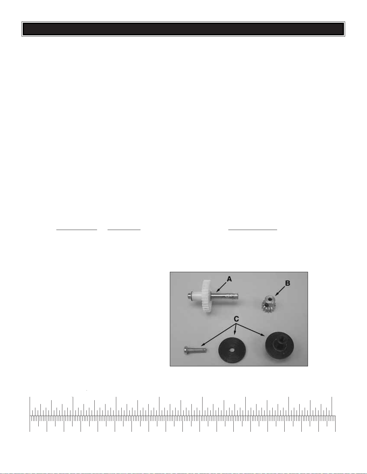
GPMG0181 ...........Gear Box
GPMG0308 ...........Motor
GPMG0861 ...........Spur Gear/Shaft (A)
GPMG0238 ...........Pinion Gear (B)
GPMQ4621 ...........Prop Adapter (C)
0" 1" 2" 3" 4" 5" 6" 7"
0 10 20 30 40 50 60 70 80 90 100 110 120 130 140 150 160 170 180
Inch Scale
Metric Scale
To convert inches to millimeters, multiply inches by 25.4
Page 7
❏ 1. If you have not done so already, remove the major
parts of the kit from the box (wing, fuselage, tail parts, etc.)
and inspect them for damage. If any parts are damaged or
missing, contact Product Support at the address or
telephone number on the front cover.
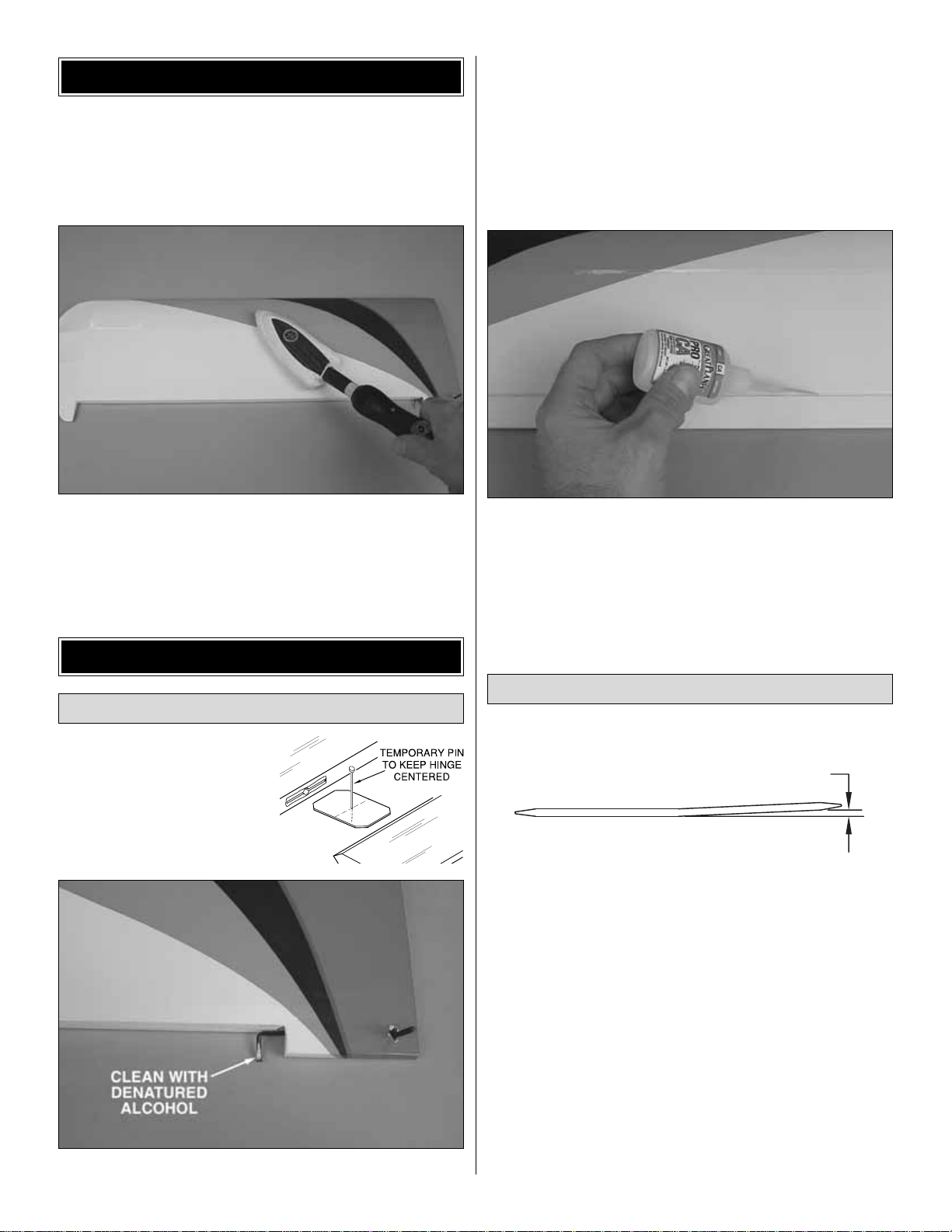
❏ 2. Remove the masking tape and separate the ailerons
from the wing and the rudder from the fin. If necessary, use
a covering iron set on medium/high to tighten the covering.
Apply pressure over sheeted areas to thoroughly bond the
covering to the wood.
❏❏1. Test fit the ailerons to
the wing with the supplied CA
hinges. If the hinges don’t stay
centered, stick a pin through
the middle of the hinges to hold
them in position.
❏❏2.Clean the aileron torque rods with denatured alcohol.
❏❏3. Mix a small amount of epoxy. Using a tooth pick,
apply epoxy in the aileron torque rod hole and along the
groove in the leading edge of one of the ailerons.Before the
epoxy sets, join the aileron to the wing. Remove any pins
you may have inserted into the hinges. Adjust the aileron so
there is a very small gap between the LE of the aileron and
the wing. The gap should be small–just enough to see light
through or to slip a piece of paper through.
❏❏4. Apply six drops of thin CA to the top and bottom of
each hinge. Do not use CA accelerator. After the CA
and epoxy have fully hardened, test the hinges by pulling on
the ailerons.
❏ 5. Go back to step 1 and repeat the hinge installation for
the other aileron.
❏ 1. Without using any glue, temporarily join the wings
with the plywood wing joiner. Make adjustments as
necessary for a good fit.Note: The dihedral angle is factoryset and determined by the angle of the joiner and the joining
ribs on the ends of the wing halves. However, you may
confirm the dihedral by placing one wing panel flat on the
workbench and measuring the distance between the bottom
of the rib on the end of the other panel and the bench. The
distance should be 1-7/16" [37mm], but a small variance is
acceptable.If the wing doesn’t fit well or if you can’t get close
enough to the dihedral specified, there may be excess glue
inside the wing or irregularities on the joiner. Use coarse
sandpaper to true the edges and bevel the corners of the
joiner and/or use a hobby knife to remove any glue from the
joiner openings in the ribs on the end of the wing halves.
Join the Wing Halves
Install the Ailerons
ASSEMBLE THE WING
PREPARATIONS
7
1-7/16" [37mm]
Page 8
❏ 2. Prepare 1/2 oz. of 30-minute epoxy. Working quickly,
thoroughly coat the inside of both wing halves where the
joiner fits and one half of the joiner with epoxy. Making certain
the joiner is upright, insert the coated end into one of the
wing halves.Coat the other end of the joiner and the root ribs
with the remainder of the epoxy. Join the wing halves tightly,
holding them together. Use a paper towel dampened with
denatured alcohol to wipe away the e xcess epo xy that comes
out of the wing. Tightly hold the wing together with several
strips of masking tape on the top and bottom, making certain
both halves are in full contact and the leading and trailing
edges are aligned. Let the wing set until the epoxy has set.
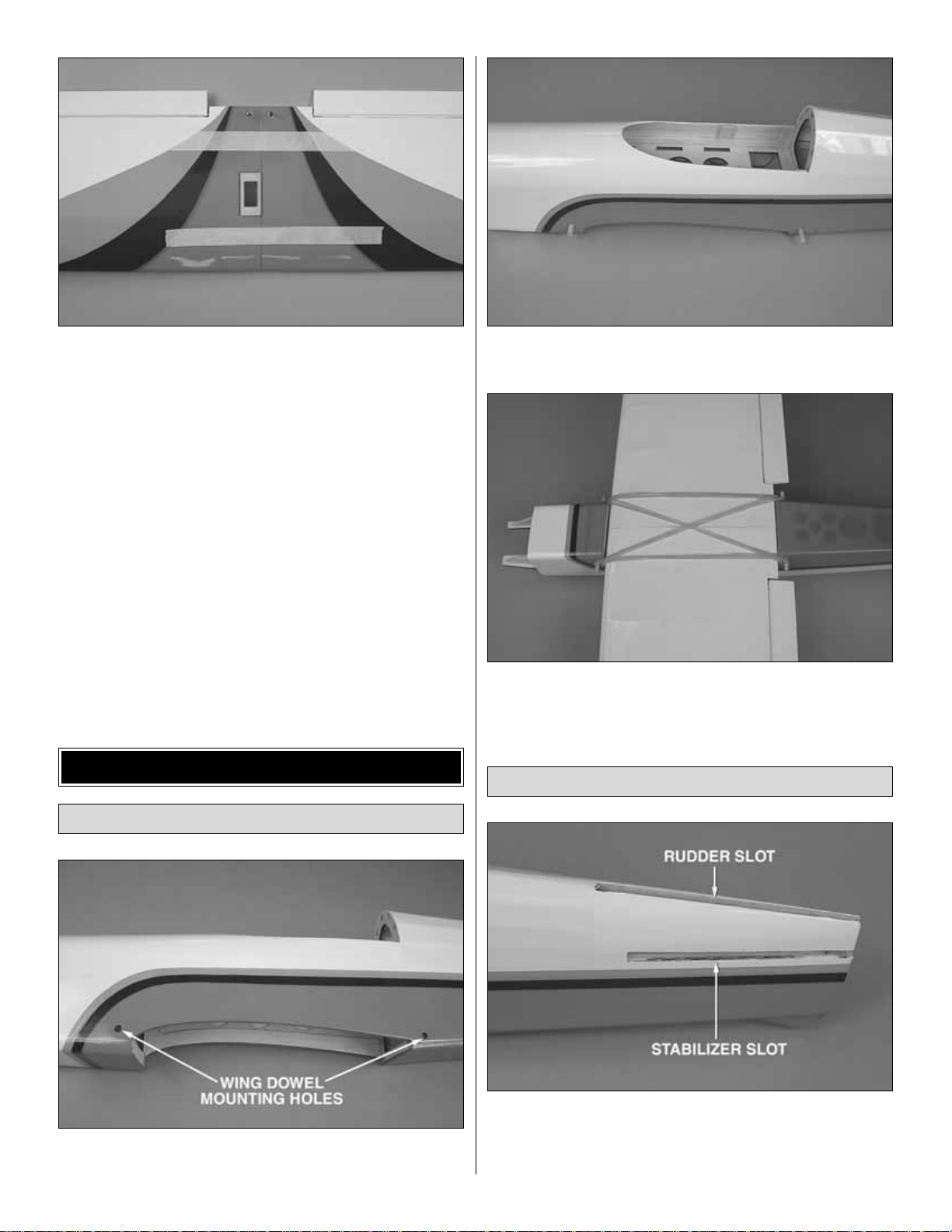
❏ 1. Cut the covering from the four wing mounting dowel
holes on the sides of the fuselage.
❏ 2. Center the two 4mm x 80mm hardwood wing mounting
dowels in the holes.Use thin CA to glue the dowels in place.
❏ 3.Install the wing on the fuselage using four rubber bands.
❏ 1. Using a shar p hobby knife, remove the covering from
the stabilizer slot at the aft end of the fuselage and from the
rudder slot in the top of the fuselage. Also remove the
temporary balsa block from the stabilizer slot.
Mount the Stabilizer and Fin
Mount the Wing
ASSEMBLE THE FUSELAGE
8
Page 9

❏ 2. Mark the center of the trailing edge of the stabilizer.
Insert the stabilizer into the slot, centering the mark you made
on the TE of the stabilizer with the aft end of the fuselage.
❏ 3. Stick a T-pin into the center of the top of the firewall.
Tie a small loop in one end of a 36" [910mm] piece of nonelastic string such as K&S #801 Kevlar thread.Slip the loop
in the string over the T-pin.
❏ 4. Fold a piece of masking tape over the other end of the
string and draw an arrow on it.With the stab centered on the
fuselage, slide the tape along the string and align the arrow
with one tip of the stab. Swing the string over to the same
position at the other end of the stab. If the arrow doesn’t
align with the tip, adjust the stab and the arrow slightly and
check both tips again.Adjust the stab until the stabilizer tips
and the trailing edge are centered.
❏ 5.View the stab from approximately 10' [3m] behind the
plane.Check that the stab is parallel with the wing.If it is not,
lightly sand the stab saddle until the stab is parallel with
the wing.
❏ 6. Use a fine-point felt-tip pen to mark the outline of the
fuselage onto the bottom and top of the stab.
❏ 7. Remove the stab from the fuselage. Use a sharp #11
hobby knife or the Expert Tip that follows to cut the covering
from the stab just inside the lines you marked. Use care to
cut only the covering and not the wood. Cutting the wood
will weaken the stab and it may break in flight.
9
Page 10

HOW TO CUT COVERING FROM BALSA
Use a 25 watt soldering iron to cut the covering from the stab.
The tip of the soldering iron doesn’t have to be sharp, but a
fine tip does work best.Allow the iron to heat fully .Use a metal
straightedge to guide the soldering iron at a rate that will just
melt the covering and not burn into the wood.The hotter the
soldering iron, the faster it must travel to melt a fine cut.Allow
the heat to melt the covering.Do not apply much pressure or
the wood may be damaged.Peel off the covering.
❏ 8. Apply a light coat of 30-minute epoxy in the stabilizer
slot and the top and bottom of the stabilizer. Slide the
stabilizer into position. Make sure the stabilizer is centered
from side-to-side using the string method to re-align the stab
with the fuselage. Inser t the fin into the fin slot, but do not
insert it completely. The fin is used to space the fin slot
correctly while the epoxy sets. Wipe off the excess epoxy
with a paper towel dampened with denatured alcohol. Allow
the epoxy to set completely before installing the fin.
❏ 9. Fit the fin all the way into the fin slot.Again, use a felt-
tip pen to mark the fuselage onto the fin. Remove the fin
from the fuselage and remove the covering from the fin.
❏ 10. Glue the fin into position using epoxy. Use a builder’s
square to make sure the fin is perpendicular to the stab.
Wipe off the excess epoxy with a paper towel dampened
with denatured alcohol. Masking tape can be used to hold
the fin in position until the epoxy sets.
❏ 11. Use a sharp hobby knife to trim the covering from the
notch in the leading edge of the rudder.
❏ 12. Join the rudder to the fin using three CA hinges. Use
thin CA to glue the CA hinges in the rudder and fin following
the same procedure used for the ailerons.
❏ 1. Position one of the aluminum motor brackets 1/4"
[6mm] back from the forward edge of the mounting rails.Set
the motor on the motor bracket so that the aft edge of the
motor is 3/16" [5mm] from the firewall.
MOUNT THE MOTOR
10
Page 11

❏ 2. Place the second motor bracket over the motor and
drill a 1/32" [.8mm] pilot hole at each mounting hole in the
motor bracket. Secure the motor brackets to the mounting
rail with 2x7mm sheet metal screws. Rotate the
motor/geardrive so that the gear drive is aligned with the
firewall.Then tighten the screws.
❏ 3. Use the hex wrench to loosen the set screw in the prop
adapter and remove the prop adapter from the gear drive.
Tape a piece of paper to each side of the fuselage e ven with
the front of the fuselage.
❏ 4. Slide the cowl onto the fuselage and under the paper.
Reinstall the prop adapter on the gear drive. Tighten the set
screw on the flat of the gear drive output shaft.Tape the cowl to
the fuselage so that the prop adapter is centered in the hole in
the front of the cowl and the front of the cowl is approximately
1/16" [2mm] back from the flange on the prop adapter.
❏ 5.Drill two 1/32" [.8mm] holes through both sides of the
cowl and the fuselage 1/8" [3mm] behind the front edge of
the paper. Remove the cowl and the paper. Enlarge the
holes in the cowl only with a 1/16" [2mm] drill.Then, mount
the cowl with four 2x7mm washer-head screws.
❏ 6. Remove the screws and cowl.Apply a drop of thin CA
in each hole to harden the wood.Reinstall the cowl and prop
adapter after the CA has hardened.
Note: You will need to have your 8-cell motor battery
charged later in this section. Star t charging it now so
you do not have to wait for it to charge later.
Install the Control Horns
RADIO INSTALLATION
11
Page 12

❏ 1. Inser t the two wire pushrods into the outer pushrod
tubes inside the fuselage. Using a sharp hobby knife, cut a
small slot in the covering, where the pushrods press against
the covering, to allow the pushrods to exit the fuselage.
❏ 2.Remove and reinstall the pushrods so that the Z-bends
are at the aft end of the fuselage. On the right pushrod,
insert the Z-bend into the outer hole of a nylon control horn.
This pushrod will be for the elevator. On the left pushrod,
insert the Z-bend into the second hole from the end. Position
the control horn on the elevator so that the attachment holes
are aligned with the hinge line.
❏ 3. Mark the two control horn mounting holes on the
elevator. Remove the control horn and drill 5/64" [2mm]
holes through the elevator at the marks. Mount the control
horn with two 2x9mm machine screws and the nylon
mounting plate on the top of the elevator.
❏ 4. Install the rudder control horn following the same
procedure. Make sure that the control horn does not
interfere with the elevator.
❏ 1. Install a pushrod connector on the elevator servo arm,
1/4" [6mm] from the center of the servo arm. Install a second
pushrod connector on the rudder servo arm, 5/16" [8mm]
from the center of the servo arm. First insert the pushrod
connector though the horn, then install a 2mm washer and
a 2mm nut on the connector.Install a 3mm set screw in the
top of the pushrod connector.
Install the Servos
12
Page 13

❏ 2. Install the r udder and elevator servos in the servo tray.
Insert the pushrods through the pushrod connectors and
install the servo arms on the rudder and elevator servos.Align
the pushrod connectors with the pushrods.Use the hardware
included with the servos to mount the servos to the tray.
❏ 3. Cut a piece of soft hook-and-loop material and use CA
to glue it to the bottom of your receiver .Cut an opposite piece
of the hook-and-loop material and glue it to the bottom of the
battery tray, centered between the three slots. Connect the
rudder and elevator servos to the receiver and mount the
receiver to the battery tray. Optional: Use double-sided foam
tape (not included) to attach the receiver to the battery tray.
❏ 4.Trim the covering from the five cooling air exit holes aft
of the wing saddle. Route the receiver antenna out one of
the holes and tape it to the bottom of the fuselage.
❏ 5. Connect the electronic speed control (not included) to
the motor leads. If the ESC to be installed does not have
bullet connectors, you will need to install the included
connectors on the ESC. If the ESC has an on/off switch,
mount it through the side of the fuselage. Connect the ESC
to the throttle channel in the receiver.
❏ 6. Use a sharp kniffe to strip 3/16" [5mm] of the insulation
from the end of the ESC wire. Insert the wire in the bullet
connector and use pliers to crimp the connector around the
wire.Place a piece of clear heat shrink aound the connector
and use a heat gun to shrink it.
❏ 7. Switch on the transmitter, connect the charged motor
battery and switch on the ESC. Center the rudder and
elevator trims. If necessary, remove the servo arms and
reinstall them perpendicular to the centerline of the ser vo.
Reinstall the servo arm screws.
❏ 8. Center the elevator and rudder, then tighten the set
screws in the pushrod connectors. Trim off the excess
pushrod wires 1/4" [6mm] past the connectors.
13
Page 14
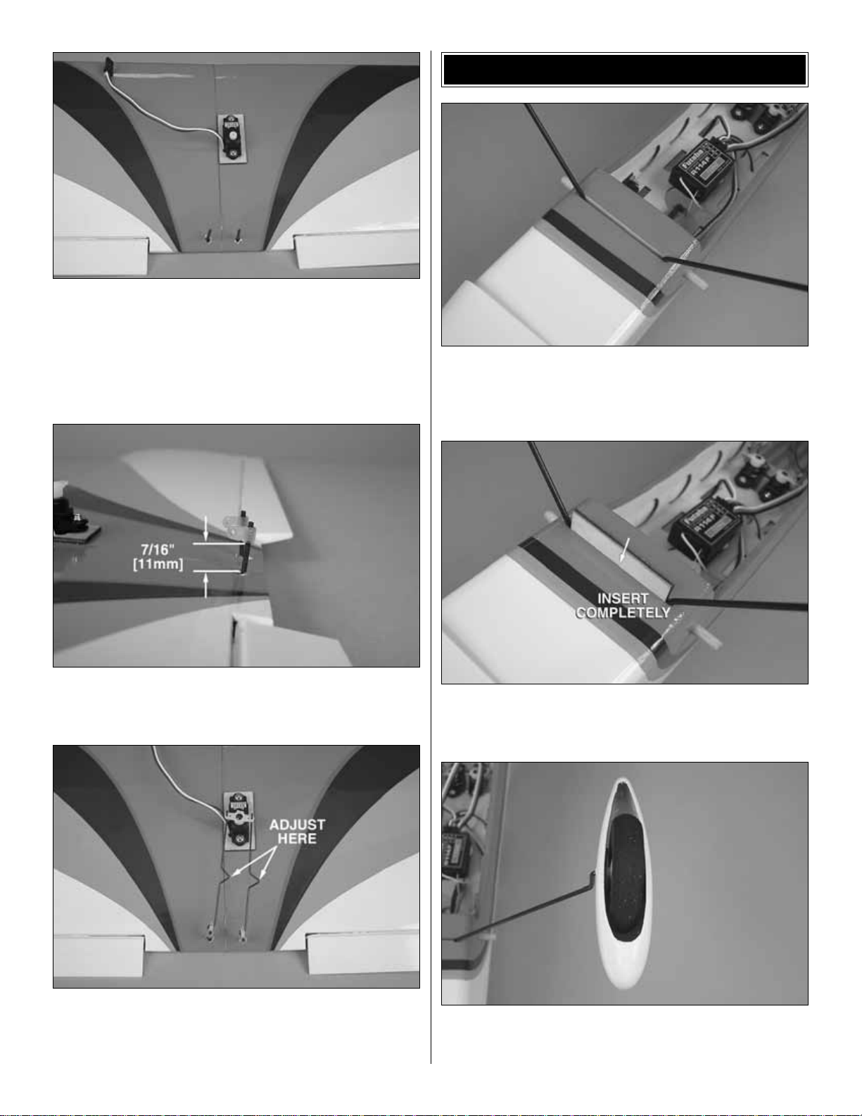
❏ 9. Mount the aileron servo in the wing. Connect a 6"
[150mm] aileron servo extension to the receiver. Connect
the aileron servo to the servo extension and switch on the
transmitter and ESC.Center the aileron servo trim.
❏ 10. Install a two-arm servo arm with both holes 5/16"
[8mm] from the center of the arm.
❏ 11. Thread the two nylon torque rod horns onto the
aileron torque rods. The bottom of the horn should be
approximately 7/16" [11mm] from the wing.
❏12.Insert one end of the aileron pushrods into the torque rod
horns. Insert the other end into the ser vo arm. Install the ser vo
arm on the aileron servo and install the servo arm screw. To
adjust the ailerons, open or close the V-bends in the pushrods.
❏ 1. Trim the covering from the main landing gear slot in the
bottom of the fuselage and insert the main landing gear wire.
❏ 2. Insert the plywood landing gear retainer in the slot. It
can either be glued in or held in place with clear tape.
❏ 3. Install both wheel pants and foam wheels by inserting
the landing gear in one side of the wheel pant, then through
the foam wheel and out the other side of the wheel pant.
MOUNT THE LANDING GEAR
14
Page 15

❏ 4. With the plane sitting on the bench, adjust the wheel
pant so that the bottom is 3/8" [9mm] from the bench.
❏ 5. Position one of the metal landing gear straps over the
main gear, against the wheel pant. Mar k the screw holes,
remove the strap and drill a 1/32" [.8 mm] pilot hole at each
mark. Mount the straps to the wheel pants with 2x4mm
sheet metal screws.
❏ 1. Use a scissors designed to cut plastic to carefully trim
the canopy along the molded cut lines.
❏ 2.Center the canopy on the fuselage.Cut a canopy hinge
strip from the decal sheet.Attach the canopy to the right side
of the fuselage with the decal hinge strip.
❏ 3. Use a piece of tape to hold the left side of the canopy
tight to the fuselage. Note the location of the plywood
doubler inside the cockpit side wall.Drill a 1/16" [2mm] hole
through the canopy and plywood doubler. Enlarge the hole
in the fuselage to 7/64" [3.5mm]. Apply a drop of thin CA to
the hole in the fuselage.After the CA has hardened, run the
drill back though the hole to clean it out.
❏ 4. Attach the 2.3 x 12mm tube to the inside of the canopy
with a 2x7mm sheet metal screw.
❏ 5.To close the canopy, insert the tube in the hole in the
side of the fuselage.
❏ 1. To make the battery strap, overlap the two pieces of
hook-and-loop material as shown.
Mount the Battery
Mount the Canopy
FINISH THE MODEL
15
Page 16

❏ 2.Insert the hook-and-loop strap through the middle slots
from the bottom of the battery tray. Position the strap over
the receiver to help hold it in place.
❏ 3. Insert the motor battery in the cockpit and trim the
hook-and-loop strap so that it holds the battery secure.
❏ 4.To prevent the battery from sliding around, glue a piece
of hook-and-loop material to the battery tray forward of the
strap. Once the plane has been balanced and the battery
location has been determined, glue a corresponding piece
of hook-and-loop material to the battery.
1.Use scissors or a sharp hobby knife to cut the decals from
the sheet.
2.Be certain the model is clean and free from oily fingerprints
and dust.Prepare a dishpan or small bucket with a mixture of
liquid dish soap and warm water–about one teaspoon of
soap per gallon of water.Submerse the decal in the soap and
water and peel off the paper backing.Note: Even though the
decals have a “sticky-back” and are not the water transfer
type, submersing them in soap and water allows accurate
positioning and reduces air bubbles underneath.
3. Position decal on the model where desired. Holding the
decal down, use a paper towel to wipe most of the water a way.
4. Use a piece of soft balsa or something similar to
squeegee remaining water from under the decal. Apply the
rest of the decals the same way.
Warning: Once the motor battery is connected to the
electronic speed control, stay clear of the propeller.
❏ 1. Switch on the transmitter and connect the motor
battery to the electronic speed control. Move the throttle
stick down to the off position. Switch on the speed control
and center the trims. If necessary, remove the servo arms
from the servos and reposition them so they are centered.
Reinstall the screws that hold on the servo arms.
❏ 2. With the transmitter and receiver still on, check all the
control surfaces to see if they are centered. If necessary,
adjust the pushrods at the pushrod connectors to center the
control surfaces.
❏ 3. Make certain that the control surfaces respond in the
correct direction as shown in the diagram. If any of the
Check the Control Directions
GET THE MODEL READY TO FLY
Apply the Decals
16
4-CHANNEL RADIO SETUP
(STANDARD MODE 2)
4-CHANNEL
TRANSMITTER
ELEVATOR MOVES UP
4-CHANNEL
TRANSMITTER
RIGHT AILERON MOVES UP
LEFT AILERON MOVES DOWN
RUDDER MOVES RIGHT
FULL THROTTLE
4-CHANNEL
TRANSMITTER
4-CHANNEL
TRANSMITTER
Page 17

controls respond in the wrong direction, use the servo
reversing in the transmitter to reverse the servos connected
to those controls. Be certain the control surfaces have
remained centered. Adjust if necessary.
❏ 4. To operate or “arm” the motor, follow the instructions
included with your electronic speed control.
Use a Great Planes AccuThrow (or a ruler) to accurately
measure and set the control throw of each control surface as
indicated in the chart that follows.If your radio does not hav e
dual rates, we recommend setting the throws at the low rate
setting.NOTE: The throws are measured at the widest part
of the elevators, rudder and ailerons.
❏ 1. Drag the edge of a hobby knife along the edge of the
propeller to remove the sharp edges.
❏ 2. Remove the prop washer and screw from the prop
adapter.Install the propeller on the prop adapter and secure
it with the prop washer and screw.
❏ 3.Check the rotation of the prop by switching on the radio
system and arming the ESC. Move the throttle stick to full
power. If the prop is turning the wrong direction (no air
blowing back towards the fuselage), switch the leads
between the motor and the ESC.
Mount the Propeller
IMPORTANT: The Mini Super Sportster EP has been
extensively flown and tested to arrive at the throws at
which it flies best. Flying your model at these throws will
provide you with the greatest chance for successful first
flights. If, after you have become accustomed to the way
the Mini Super Sportster EP flies, you would like to
change the throws to suit your taste, that is fine.However,
too much control throw could make the model difficult to
control, so remember, “more is not always better.”
These are the recommended control surface throws:
High Rate Low Rate
ELEVATOR: 5/16" [8mm] up 3/16" [5mm] up
5/16" [8mm] down 3/16" [5mm] down
RUDDER: 1" [25mm] right 3/4" [19mm] right
1" [25mm] left 3/4" [19mm] left
AILERONS: 1/4" [6mm] up 1/8" [3mm] up
1/4" [6mm] down 1/8" [3mm] down
Set the Control Throws
17
Page 18

At this stage the model should be close to ready-to-fly
condition with all of the systems in place including the motor,
landing gear, motor battery, and the radio system.
❏ 1.Use a felt-tip pen or 1/8" [3mm]-wide tape to accurately
mark the C.G. on the top of the wing on both sides of the
fuselage.The C.G. is located 2-3/16" [56mm] back from the
leading edge of the wing.
❏ 2.With the wing attached to the fuselage, all parts of the
model installed (ready to fly) and the motor battery installed,
place the model upside-down on a Great Planes CG Machine,
or lift it upside down at the balance point you marked.
❏ 3. If the tail drops, the model is “tail heavy” and the motor
battery and/or receiver must be shifted forward or weight m ust
be added to the nose to balance.If the nose drops, the model
is “nose hea vy”and the motor battery and/or receiver must be
shifted aft or weight must be added to the tail to balance. If
possible, move the motor battery and receiver forward or aft
to minimize or eliminate any additional ballast required. If
additional weight is required, use Great Planes [GPMQ4485]
“stick on”lead. A good place to add stick-on nose weight is to
the firewall (don’t attach weight to the cowl-it is not intended
to support weight). Begin by placing incrementally increasing
amounts of weight on the bottom of the fuse over the firewall
until the model balances. Once you have determined the
amount of weight required, it can be permanently attached. If
required, tail weight may be added by cutting open the bottom
of the fuse and gluing it permanently inside.
If moving the motor battery forward or aft will balance the
plane without adding additional weight, mark the battery tray
or the fuselage inside where the aft end of the battery
should be placed. This will allow you to position the battery
correctly before each flight.
❏ 4. IMPORTANT: If you found it necessary to add any
weight, recheck the C.G.after the weight has been installed.
❏1.With the wing level lift the model by the prop shaft and the
bottom of the fuse under the TE of the fin.Do this several times.
❏ 2. If one wing always drops when you lift the model,
it means that side is heavy. Balance the airplane by
adding weight to the other wing tip. An airplane that has
been laterally balanced will track better in loops and
other maneuvers.
No matter if you fly at an AMA sanctioned R/C club site or if you
fly somewhere on your own, you should always have your
name, address, telephone number and AMA number on or
inside your model.It is required at all AMA R/C club flying sites
and AMA sanctioned flying events. Fill out the identification tag
on page 23 and place it on or inside your model.
Follow the battery charging instructions that came with your
radio control system to charge the transmitter. You should
always charge your transmitter the night before you go flying
and at other times as recommended by the radio manuf acturer .
Charge the Batteries
Identify Y our Model
PREFLIGHT
Balance the Model Laterally
This is where your model should balance for the first
flights. Later, you may wish to experiment by shifting the
C.G. up to 3/16" [5mm] forward or 3/16" [5mm] back to
change the flying characteristics. Moving the C.G. forward
may improve the smoothness and stability, but the model
may then require more speed for tak eoff and mak e it more
difficult to slow for landing.Moving the C.G.aft makes the
model more maneuverable, but could also cause it to
become too difficult to control. In any case, start at the
recommended balance point and do not at any time
balance the model outside the specified range.
More than any other factor, the C.G. (balance point) can
have the greatest effect on how a model flies and may
determine whether or not your first flight will be
successful. If you value this model and wish to enjoy it for
many flights, DO NOT OVERLOOK THIS IMPORTANT
PROCEDURE. A model that is not proper ly balanced will
be unstable and possibly unflyable.
Balance the Model (C.G.)
18
2-3/16" [56mm]
Page 19

Carefully balance your propeller and spare propellers before
you fly. An unbalanced prop can be the single most
significant cause of vibration that can damage your model.
Not only will motor mounting screws and bolts loosen,
possibly with disastrous effect, but vibration may also
damage your radio receiver and battery.
We use a Top Flite Precision Magnetic Prop Balancer
™
[TOPQ5700] in the workshop and keep a Great Planes
Fingertip Prop Balancer [GPMQ5000] in our flight box.
1. The included motor will benefit from a shor t “break-in” by
running the motor at full throttle without the propeller for at
least 15 minutes. It is best to run the motor in 5 minute
intervals, allowing the motor to cool between runs.This will
seat the motor brushes on the commutator, insuring that the
motor will provide full power for your first flight and extend
the life of your motor. If you notice a decrease in motor
power after several flights, it may be due to carbon build-up
on the brushes or commutator. To remove this build-up,
repeat the above break-in procedure.
2.The bronze bushings in the motors are self lubricating, but
their life may be extended by applying a very small amount
of light machine oil to the point where the motor shaft
contacts the bushings after every hour or two of run time.
Note: A drop of oil is far too much.You should apply the oil
with a toothpick. Never oil the inside of the motor.
3. Using multiple battery packs to run the motor for
successive flights may cause the motor to become
excessively hot.We recommend at least a 10-minute motor
cool-down period between flights.
1.A new battery pack should be “cycled”for best results.You
should peak charge the battery, then discharge it almost
completely by actually running your motor with the propeller
attached until the auto cut-off stops the motor.To help cool
the battery, remove the battery from the plane. Do this 2 or
3 times on the ground before actually flying. Be sure you
remove the battery from the airplane between each cycle
and allow it and the motor to cool before recharging.
2. Examine your propeller for irregularities caused by the
injection molding process.Carefully remove the imperfections
with fine sandpaper.
After you break-in the motor on the model, inspect the
model closely to make sure all screws remained tight, the
hinges are secure, the prop is secure and all pushrods and
connectors are secure.
Ground check the operational range of your radio before the
first flight of the day. With the transmitter antenna collapsed
and the receiver and transmitter on, you should be able to
walk at least 100 feet [30m] away from the model and still
have control. Have an assistant stand by your model and,
while you work the controls, tell you what the control surf aces
are doing. Repeat this test with the motor running at
various speeds with an assistant holding the model, using
hand signals to show you what is happening. If the control
surfaces do not respond correctly, do not fly! Find and
correct the problem first.Look for loose servo connections or
broken wires, corroded wires on old servo connectors, poor
solder joints in your battery pack or a defective cell, or a
damaged receiver crystal from a previous crash.
Range Check
Ground Check
PERFORMANCE TIPS
PROPER CARE OF YOUR MOTOR
Balance Propellers
CAUTION: Unless the instructions that came with your
radio system state differently, the initial charge on new
transmitter and receiver batteries should be done for 15
hours using the slow-charger that came with the radio
system.This will “condition” the batteries so that the next
charge may be done using the fast-charger of y our choice.
If the initial charge is done with a fast-charger the
batteries may not reach their full capacity and you may be
flying with batteries that are only partially charged.
19
Page 20

Use safety glasses when running the motor.
Do not run the motor in an area of loose gravel or sand;the
propeller may throw such material in your face or eyes.
Keep your f ace and body as w ell as all spectators a wa y from
the plane of rotation of the propeller as you run the motor.
Keep these items away from the prop: loose clothing, shir t
sleeves, ties, scarfs, long hair or loose objects such as
pencils or screwdrivers that may fall out of shirt or jacket
pockets into the prop.
Read and abide by the following excerpts from the Academy
of Model Aeronautics Safety Code.For the complete Safety
Code refer to
Model Aviation
magazine, the AMA web site or
the Code that came with your AMA license.
1) I will not fly my model aircraft in sanctioned events, air
shows, or model flying demonstrations until it has been
proven to be airworthy by having been previously,
successfully flight tested.
2) I will not fly my model aircraft higher than approximately
400 feet within 3 miles of an airport without notifying the
airport operator .I will give right-of-way and avoid flying in the
proximity of full-scale aircraft.Where necessary, an observer
shall be utilized to supervise flying to avoid having models
fly in the proximity of full-scale aircraft.
3) Where established, I will abide by the safety rules for the
flying site I use, and I will not willfully and deliberately fly my
models in a careless, reckless and/or dangerous manner.
5) I will not fly my model unless it is identified with my name
and address or AMA number, on or in the model.Note:This
does not apply to models while being flown indoors.
7) I will not operate models with pyrotechnics (any device
that explodes, burns, or propels a projectile of any kind).
1) I will have completed a successful radio equipment ground
check before the first flight of a new or repaired model.
2) I will not fly my model aircraft in the presence of
spectators until I become a qualified flier, unless assisted b y
an experienced helper.
3) At all flying sites a straight or curved line(s) must be
established in front of which all flying takes place with the
other side for spectators.Only personnel involv ed with flying
the aircraft are allowed at or in the front of the flight line.
Intentional flying behind the flight line is prohibited.
4) I will operate my model using only radio control frequencies
currently allowed by the F ederal Communications Commission.
5) I will not knowingly operate my model within three
miles of any pre-existing flying site except in accor dance
with the frequency sharing agreement listed [in the
complete AMA Safety Code].
9) Under no circumstances may a pilot or other person touch
a powered model in flight; nor should any part of the
model other than the landing gear, intentionally touch
the ground, except while landing.
End of AMA Safety Code excerpts.
❏ 1. Check the C.G. according to the measurements
provided in the manual.
❏ 2. Be certain the motor battery and receiver are
securely mounted in the fuse.
❏ 3. Extend your receiver antenna and make sure it has a
strain relief inside the fuselage to keep tension off the
solder joint inside the receiver.
❏ 4. Balance your model
laterally
as explained in the
instructions.
❏ 5. Add a drop of oil to the axles so the wheels will
turn freely.
❏ 6. Make sure all hinges are securely glued in place.
During the last few moments of preparation your mind
may be elsewhere anticipating the excitement of the first
flight. Because of this, you may be more likely to overlook
certain checks and procedures that should be performed
before the model is flown.To help avoid this, a check list
is provided to make sure these important areas are not
overlooked. Many are covered in the instruction manual,
so where appropriate, refer to the manual for complete
instructions. Be sure to check the items off as they are
completed (that’s why it’s called a
check list!
).
CHECK LIST
Radio Control
General
AMA SAFETY CODE (E
XCERPTS
)
Failure to follow these safety precautions may result
in severe injury to yourself and others.
MOTOR SAFETY PRECAUTIONS
20
Page 21

❏ 7. Reinforce holes for wood screws with thin CA where
appropriate (servo mounting screws, cowl mounting
screws, etc.).
❏ 8. Confirm that all controls operate in the correct direction
and the throws are set up according to the manual.
❏ 9. Make sure that all servo arms are secured to the
servos with the screws included with your radio.
❏10. Secure connections between servo wires and Y-
connectors or servo extensions with vinyl tape, heat
shrink tubing or special clips suitable for that purpose.
❏11. Make sure any servo extension cords you may have
used do not interfere with other systems (servo arms,
pushrods, etc.).
❏12. Balance your propeller (and spare propellers).
❏13. Tighten the propeller nut and spinner.
❏14. Place your name, address, AMA number and
telephone number on or inside your model.
❏15. If you wish to photograph your model, do so before
your first flight.
❏16. Range check your radio when y ou get to the flying field.
The Mini Super Sportster EP is a great-flying model that flies
smoothly and predictably. The Mini Super Spor tster EP does
not, however, possess the self-recovery characteristics of a
primary R/C trainer and should be flown only by experienced
R/C pilots.
The Mini Super Sportster EP will ROG (rise off ground) very
easily from a smooth runway. Point the plane into the wind
and apply power. Once the plane gains some speed the
rudder can be used to control the direction. Because the
plane does not have a steerable tail wheel, taking off in a
cross-wind is very difficult and a hand launch is
recommended. Once the plane has gained speed,
gently
apply
up elevator , lifting the model into the air.Be smooth on
the elevator stick, allowing the model to establish a
gentle
climb to a safe altitude before turning into the traffic pattern.
If you do not have a smooth runwa y to tak e-off from, the Mini
Super Sportster EP can easily be hand launched. For the
first flight we recommend that the plane be hand launched
by an assistant. This will allow you to make quick control
corrections if the plane is out of trim.The plane only requires
a gentle level toss straight out.Do not throw the plane hard.
This usually results in a plane being thrown at a poor angle
requiring sudden drastic control corrections.Once the plane
has been trimmed to fly straight and level, it is very easy for
the pilot to hand launch the plane.
For reassurance and to keep an eye on other traffic, it is a
good idea to have an assistant on the flight line with you.Tell
him to remind you to throttle back once the plane gets to a
comfortable altitude.While full throttle is usually desirable for
takeoff, most models fly more smoothly at reduced speeds.
Tak e it easy with the Mini Super Sportster EP for the first few
flights, gradually getting acquainted with it as you gain
confidence. Adjust the trims to maintain straight and level
flight. After flying around for a while, and while still at a safe
altitude with plenty of battery power remaining, practice slow
flight and execute practice landing approaches by reducing
the throttle to see how the model handles at slower speeds.
Add power to see how she climbs as well. Continue to fly
around, executing various maneuvers and making mental
notes (or having your assistant write them down) of what trim
or C.G.changes may be required to fine tune the model so it
flies the way you like. Mind your battery power and use this
first flight to become familiar with your model before landing.
To initiate a landing approach, lower the throttle while on the
downwind leg.Allow the nose of the model to pitch downward
to gradually bleed off altitude. Continue to lose altitude, but
maintain airspeed by keeping the nose down as y ou turn onto
the crosswind leg. Make your final turn toward the runway
(into the wind) keeping the nose down to maintain airspeed
and control. Level the attitude when the model reaches the
Landing
Flight
Takeoff
CAUTION (THIS APPLIES TO ALL R/C AIRPLANES): If,
while flying, you notice an alarming or unusual sound
such as a low-pitched “buzz,” this may indicate control
surface
flutter
.Flutter occurs when a control surface (such
as an aileron or elevator) or a flying surface (such as a
wing or stab) rapidly vibrates up and down (thus causing
the noise). In extreme cases, if not detected immediately,
flutter can actually cause the control surface to detach or
the flying surface to fail, thus causing loss of control
followed by an impending crash. The best thing to do
when flutter is detected is to slow the model immediately
by reducing power, then land as soon as safely possible.
Identify which surface fluttered (so the problem may be
resolved) by checking all the servo grommets for
deterioration or signs of vibration. Make certain all
pushrod linkages are secure and free of play. If it fluttered
once, under similar circumstances it will probably flutter
again unless the problem is fixed.Some things which can
cause flutter are; Excessive hinge gap; Not mounting
control horns solidly; Poor fit of clevis pin in horn; Sideplay of wire pushrods caused by large bends; Excessive
free play in servo gears; Insecure servo mounting; and
one of the most prevalent causes of flutter;Flying an overpowered model at excessive speeds.
FLYING
21
Page 22

runway threshold, modulating the throttle as necessary to
maintain your glide path and airspeed. If you are going to
overshoot, smoothly advance the throttle (alw ays ready on the
right rudder to counteract torque) and climb out to make
another attempt. But, if your battery power is low do not
attempt to go around again. It is better to land long than risk
stalling the plane by flying too slow because the motor battery
is low on power .When you’re ready to make your landing flare
and the model is a foot or so off the deck, smoothly increase
up elevator until it gently touches down.
One final note about flying your model. Have a goal or flight
plan in mind for every flight. This can be learning a new
maneuver(s), improving a maneuver(s) y ou already kno w, or
learning how the model behaves in certain conditions (such
as on high or low rates). This is not necessarily to improve
your skills (
though it is never a bad idea!
), but more
importantly so you do not surprise yourself by impulsively
attempting a maneuver and suddenly finding that you’ve run
out of time, altitude or airspeed. Every maneuver should be
deliberate, not impulsive.For example, if you’re going to do
a loop, check your altitude, mind the wind direction
(anticipating rudder corrections that will be required to
maintain heading), remember to throttle back at the top, and
make certain you are on the desired rates (high/low rates).
A flight plan greatly reduces the chances of crashing your
model just because of poor planning and impulsive moves.
Remember to think.
Have a ball!
But always stay in control and fly in a safe manner.
GOOD LUCK AND GREAT FLYING!
22
OTHER ITEMS AVAILABLE FROM GREAT PLANES
ElectriFly™Slinger™ARF (GPMA1180)
Wingspan: 47.4 in
Wing Area: 463 sq in
Weight: 27 oz
Requires: 3-4 channel "mixing" radio (or radio and electronic mixer), 2 mini or micro servos, ESC W/BEC (15A min.),
8-cell battery and charger.
Sized for easy transport, the Slinger requires only quick final assembly before you're ready to fly. The wings are EPS foam,
precovered and ready to be taped to the plastic center section.Install the included Speed 400 motor and your radio gear,
and head for the field! A cockpit and simulated engine nacelles combine with the delta wing to mimic the B2 Bomber's
futuristic looks. Includes all hardware. A blast for intermediates and experts!
Page 23

23
ElectriFly™by Great Planes®Triton Peak Charger
(GPMM3150)
Computer-controlled for the ultimate in charging versatility and
precision.
Imagine a charger so versatile it can be used with lithium-ion and leadacid batteries as effectively as NiCd and NiMH cells.A unit that can peak
charge tiny park flyer packs and 24V car batteries alike. A charger that
can discharge as well as charge, cycle packs from 1 to 10 times
automatically, memorize peak and average battery voltages for each
cycle - and constantly display battery capacity, voltage, current and time
as each cycle progresses.Then, imagine that the charger, which can do
all this, is about the size of a thick paperback book, and weighs just over
a pound.The advanced computer technology in the Triton Peak Charger
makes it possible to accomplish all this and more, through controls and
menus so simple that programming is a breeze.For more information, log
on at www.electrifly.com - and be amazed. 1-year warranty.
OTHER ITEMS AVAILABLE FROM GREAT PLANES
Futaba®S3107 Micro Servo
(FUTM0025)
Dimensions: 0.9 x 0.4 x 0.8 in
(20 x 10 x 20mm)
Weight: 3 oz (85g)
Speed: @ 4.8V: 0.12 sec/60°
Torque: @ 4.8V: 16.7 oz/in
No matter what the application, there's
a quality Futaba servo with the right
size, strength and speed to master it.
For small aircraft, the S3107 micro
servo is a new fav orite, designed to fit
easily inside small spaces. It weighs
only 9 grams, yet delivers excellent
torque and speed!
ElectriFly™1100mAh 8-Cell NiMH Battery (GPMP0251)
Measuring 5.3" long x 1.1" wide x .50" high, this 1100mAh NiMH battery pack
provides long, reliable flight times.Conveniently preassembled, it comes shrinkwrapped with a two-pin connector already in place.
Page 24

BUILDING NOTES
Kit Purchased Date: _______________________
Where Purchased: _________________________
Date Construction Started: __________________
Date Construction Finished: _________________
Finished Weight: __________________________
Date of First Flight: ________________________
FLIGHT LOG
 Loading...