

Page 1
WARRANTY
Great Planes®Model Manufacturing Co. guarantees this kit to be free from defects in both material and workmanship at the date of purchase.This warranty does not cover
any component parts damaged by use or modification. In no case shall Great Planes’ liability exceed the original cost of the purchased kit. Fur ther, Great Planes
reserves the right to change or modify this warranty without notice.
In that Great Planes has no control over the final assembly or material used for final assembly, no liability shall be assumed nor accepted for any damage resulting from the
use by the user of the final user-assembled product.By the act of using the user-assembled product, the user accepts all resulting liability.
If the buyer is not prepared to accept the liability associated with the use of this product, the buyer is advised to return this kit immediately in new and unused condition to
the place of purchase.
To make a warranty claim send the defective part or item to Hobby Services at the address below:
Hobby Services
3002 N. Apollo Dr. Suite 1
Champaign IL 61822
USA
Include a letter stating your name, return shipping address, as much contact information as possible (daytime telephone number, fax number, e-mail address), a
detailed description of the problem and a photocopy of the purchase receipt.Upon receipt of the package the problem will be evaluated as quickly as possible.
READ THROUGH THIS MANU AL BEFORE ST ARTING
CONSTRUCTION. IT CONTAINS IMPORTANT
WARNINGS AND INSTRUCTIONS CONCERNING
THE ASSEMBLY AND USE OF THIS MODEL.
GPMZ0288 for GPMA1155 V1.0© Copyright 2003
Champaign, Illinois
(217) 398-8970, Ext 5
airsupport@greatplanes.com
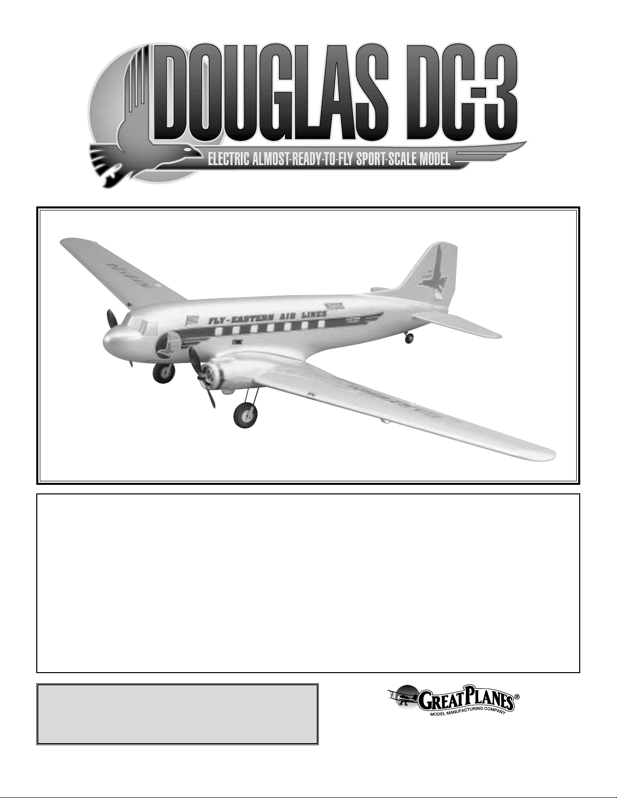
INSTRUCTION MANUAL
Wingspan: 59-3/8 in [1,510mm]
Wing Area: 393 sq in [25.3 dm2]
Weight: 3 lb [1,360 g]
Wing Loading: 17.6 oz/sq ft [53.7 g/dm2]
Length: 36-7/8 in [940mm]
Radio: 4-Channel
Motors: (2) Speed 400 Electric motors supplied
Page 2
INTRODUCTION................................................................2
SAFETY PRECAUTIONS..................................................2
DECISIONS YOU MUST MAKE ........................................3
Radio Equipment ................................................................3
Chargers.............................................................................3
ADDITIONAL ITEMS REQUIRED.....................................4
Adhesives and Building Supplies.......................................4
Optional Supplies and Tools...............................................4
IMPORTANT ASSEMBLY NOTES ....................................4
KIT CONTENTS .................................................................5
ORDERING REPLACEMENT PARTS...............................6
METRIC CONVERSIONS..................................................6
PREPARATIONS................................................................7
BUILD THE WING..............................................................7
Assemble the Wing............................................................7
Mount the Motors...............................................................8
Install the Motor Cowls .......................................................9
Install the Landing Gear.....................................................9
Install the Aileron Servos .................................................10
Fit the Wing to the Fuselage............................................10
WORKING WITH FIBERGLASS .....................................11
ASSEMBLE THE FUSELA GE.........................................11
Install the Formers ...........................................................11
Install the Servos..............................................................12
Install the Tail Surfaces ....................................................12
Install the Radio ...............................................................14
Apply the Decals..............................................................15
GET THE MODEL READY TO FLY..................................16
Check the Control Directions ...........................................16
Set the Control Throws.....................................................16
Balance the Model (C.G.).................................................17
Balance the Model Laterally.............................................17
PREFLIGHT.....................................................................17
Identify Your Model...........................................................17
Charge the Batteries........................................................17
Ground Check..................................................................18
Range Check...................................................................18
MOTOR SAFETY PRECAUTIONS .................................18
AMA SAFETY CODE......................................................18
General............................................................................18
Radio Control...................................................................18
CHECK LIST ...................................................................19
FLYING ............................................................................19
Takeoff .............................................................................19
Flight..................................................................Back Cover
Landing..............................................................Back Cover
Congratulations and thank you for purchasing the Great
Planes DC-3 EP ARF.The DC-3 EP ARF is a great flying, lowwing model that is about as simple-to-assemble as they get.In
just a few evenings you can have your DC-3 ready to fly.
The DC-3 EP ARF is a sport scale model of the full size DC-3.
It is relatively easy to fly and has no bad characteristics.
Howev er , if you hav e nev er flown an R/C model bef ore, learning
to fly the DC-3 EP ARF all by yourself is not recommended.As
with any airplane, you should find an experienced modeler to
help you with your first flights.Information about R/C clubs and
instructors is provided later in this manual.
For the latest technical updates or manual corrections to the
DC-3 EP ARF visit the Great Planes web site at
www.g reatplanes.com.Open the “Airplanes”link, then select
the DC-3 EP ARF. If there is new technical information or
changes to this model a “tech notice” box will appear in the
upper left corner of the page.
Attention: The product you have purchased is
powered by a rechargeable battery.At the end of its useful life,
under various state and local laws, it ma y be illegal to dispose
of this battery into the municipal waste system. Check with
your local solid waste officials for details in your area for
recycling options or proper disposal.This product contains a
chemical known to the state of California to cause cancer
and birth defects or other reproductive harm.
1. Your Great Planes DC-3 EP ARF should not be
considered a toy, but rather a sophisticated, working model
that functions very much like a full-size airplane.Because of
its performance capabilities, the Great Planes DC-3 EP
ARF, if not assembled and operated correctly, could possibly
cause injury to you or spectators and damage to property.
2. You must assemble the model according to the
instructions. Do not alter or modify the model, as doing so
may result in an unsafe or unflyable model. In a few cases
the instructions may differ slightly from the photos.In those
instances the written instructions should be considered
as correct.
3.You must take time to assemble straight, true and strong.
4. You must use an R/C radio system that is in first-class
condition. This model requires mini or micro servos and a
micro receiver.
PRO TECT YOUR MODEL,Y OURSELF
& OTHERS...FOLLOW THESE
IMPORTANT SAFETY PRECAUTIONS
INTRODUCTIONTABLE OF CONTENTS
2
Page 3
5. You must properly install all R/C and other components so
that the model operates properly on the ground and in the air.
6. You must test the operation of the model before every
flight to insure that all equipment is operating and that the
model has remained structurally sound. Be sure to check all
connectors often and replace them if they show signs of
wear or fatigue.
7. If you are not already an experienced R/C pilot, you
should fly the model only with the help of a competent,
experienced R/C pilot.
8. WARNING: The fuselage included in this kit is made of
fiberglass, the fibers of which may cause eye, skin and
respiratory tract irritation. Never blow into a part to remove
fiberglass dust, as the dust will blow back into your eyes.
Always wear safety goggles, a particle mask and rubber
gloves when grinding, drilling and sanding fiberglass parts.
Vacuum the parts and the work area thoroughly after
working with fiberglass parts.
Remember:Take your time and follow directions to end
up with a well-built model that is straight and true.
If you have not flown this type of model before, we
recommend that you get the assistance of an experienced
pilot in your R/C club for your first flights. If you’re not a
member of a club, your local hobby shop has information
about clubs in your area whose membership includes
experienced pilots.
In addition to joining an R/C club, we strongly recommend y ou
join the AMA (Academy of Model Aeronautics). AMA
membership is required to fly at AMA sanctioned clubs.There
are over 2,500 AMA chartered clubs across the country.
Among other benefits, the AMA provides insurance to its
members who fly at sanctioned sites and events .Additionally,
training programs and instructors are available at AMA club
sites to help you get started the right way. Contact the AMA at
the address or toll-free phone number below:
Academy of Model Aeronautics
5151 East Memorial Drive
Muncie, IN 47302-9252
Tele. (800) 435-9262
Fax (765) 741-0057
Or via the Internet at:
http://www.modelaircraft.org
This is a partial list of items required to finish the DC-3 EP
ARF that may require planning or decision making before
starting to build. Order numbers (in parentheses) are
provided for your convenience.
The DC-3 EP ARF requires a four-channel radio with a micro
receiver and four mini or micro servos.You will also need (2) 12"
servo extensions and a “Y”connector for the aileron servos.
Suggested servos:
• (HCAM0090) Hobbico®CS-5, 16.7 oz-in torque
• (HCAM0100) Hobbico CS-15, 15 oz-in torque
• (FUTM0037) Futaba®S3103, 16.6 oz-in torque
• (FUTM0025) Futaba S3107, 16.6 oz-in torque
Suggested receivers:
• (GPML0044) Great Planes 4-channel FM, low band
• (GPML0045) Great Planes 4-channel FM, high band
• (FUTL0442) Futaba 4-channel FM, low band
• (FUTL0443) Futaba 4-channel FM, high band
Low band - channels 11-35
High band - channels 36-60
Receiver crystal:
• (FUTL62**) for GPM low band
• (FUTL63**) for GPM high band
• (FUTL62**) for FUT low band
• (FUTL63**) for FUT high band
** desired channel
Recommended battery:
• (GPMA2431) Great Planes 8-cell 9.6 volt, 1800 mAh
rechargeable NiMH
The best type of charger to use is a peak charger, because
it charges the batteries until they are fully charged, then
automatically switches to a trickle charge mode.The Great
Planes ElectriFly™Peak Charger (GPMM3000) is suitable
for nigh batteries, NiCds and transmitter battery packs.The
Great Planes Triton™charger (GPMM3150) is also suitable.
If you have another type of charger that is not a peak
charger, you will have to calculate the length of time it takes
to charge the batteries yourself, then turn the charger off
when the batteries are fully charged. Overcharging the
batteries may damage them. Before you can calculate the
time it takes to charge a battery pack, you first have to know
the charge rate you are going to use.
Charger
Radio Equipment
DECISIONS YOU MUST MAKE
Note: We, as the kit manufacturer, provide you with a top
quality kit and great instructions, but ultimately the quality
and flyability of your finished model depends on how you
build it; therefore, we cannot in any way guarantee the
performance of your completed model and no
representations are expressed or implied as to the
performance or safety of your completed model.
3
Page 4
Charge rate/time recommendations:
• Charge a fully discharged 8-cell, 1100 mAh battery pack
at 1 Amp for 1 hour 10 minutes.
• Charge a fully discharged 8-cell, 1800 mAh battery pack
at 1.5 Amps for 1 hour 15 minutes.
Note:The period required to charge the batteries in the example
above is for discharged batteries. If the battery you are going to
charge is not discharged (and you are not using a peak
charger), connect it to the motors on your model.Run them until
the motors stop, thus discharging the battery.
CAUTION: Do not attempt to use Deans®Ultra Plugs with
the plug that is supplied on the electronic speed control.
They are not compatible and may be damaged if used.
In addition to the equipment listed in the “Decisions You
Must Make” section, following is the “short list” of the most
important items required to assemble the DC-3 EP ARF.
We
recommend Great Planes Pro™CA and Epoxy glue.
❏ 1/2 oz. Thin Pro CA (GPMR6001)
❏ 1/2 oz. Medium Pro CA+ (GPMR6007)
❏ Pro 6-Minute Epoxy (GPMR6045)
❏ Pro 30-Minute Epoxy (GPMR6047)
❏ Hobby Knife (HCAR0105)
❏ #11 Blades (HCAR0211)
❏ Small Phillips and Flat Blade Screwdrivers
❏ Pliers with Wire Cutter (HCAR0630)
❏ Sealing Iron (TOPR2100)
❏ Velcro
®
Hook & Loop Material (GPMQ4480)
❏ Electr ic Drill and 1/16" [1.6mm] Dr ill Bit
❏ Rubbing Alcohol (for epoxy clean up)
❏ 220-Gr it Sandpaper
❏ Pro Threadlocker (GPMR6060)
Here is a list of optional tools mentioned in the manual that
will help you assemble the DC-3 EP ARF.
❏ Great Planes CG Machine
™
(GPMR2400)
❏ Top Flite
®
Hot Sock™iron cover (TOPR2175)
❏ Straightedge with scale (HCAR0475)
❏ Masking Tape (TOPR8018)
❏ CA Debonder (GPMR6039)
❏ CA Applicator tips (GPMR6033)
❏Curved-tip canopy scissors f or trimming plastic (HCAR0667)
• When you see the term
test fit
in the instructions, it
means that you should first position the part on the
assembly without using any glue, then slightly modify or
custom fit
the part as necessar y for the best fit.
• Whenever the term
glue
is written you should rely upon
your experience to decide what type of glue to use.When a
specific type of adhesive works best for that step, the
instructions will make a recommendation.
• Whenever just
epoxy
is specified you may use
either
30-minute (or 45-minute) epoxy or6-minute epoxy. When
30-minute epoxy is specified it is highly recommended that
you use only 30-minute (or 45-minute) epoxy, because you
will need the working time and/or the additional strength.
• Photos and sketches are placed before the step they
refer to. Frequently you can study photos in following steps
to get another view of the same parts.
• The stabilizer and wing incidences and motor thrust
angles have been factory-built into this model. However,
some technically-minded modelers may wish to check these
measurements anyway.To vie w this inf ormation visit the web
site at
www.greatplanes.com
and click on “Technical Data.”
Due to manufacturing tolerances which will have little or no
effect on the way your model will fly, please expect slight
deviations between your model and the published values.
NOTE: The hardware supplied with this product is
metric; therefore the sizes and measurements in this
manual will be stated as metric sizes.
IMPORTANT BUILDING NOTES
Optional Items
Adhesives and Building Supplies
ADDITIONAL ITEMS REQUIRED
IMPORTANT: Monitor the temperature of the battery
frequently. If the battery becomes warm, disconnect it
from the charger.
4
Page 5
5
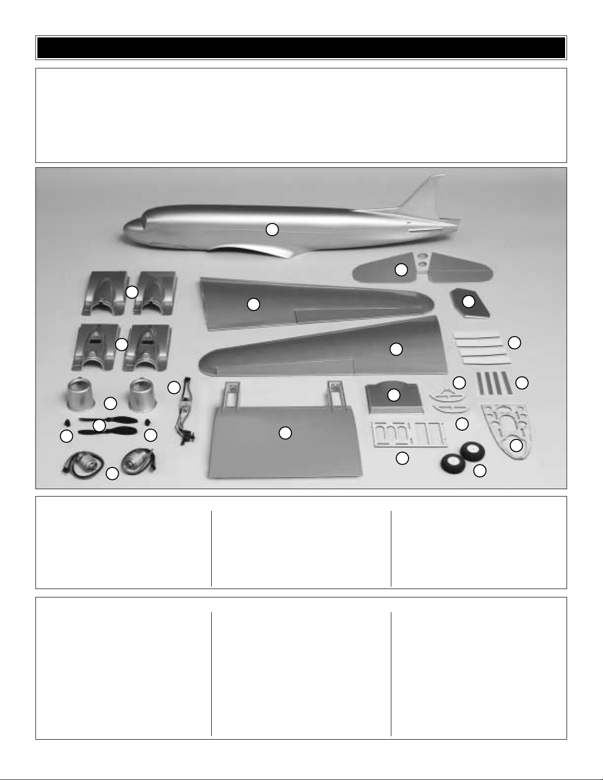
Before starting to build, use the Kit Contents list to take an inventory of this kit to make sure it is complete and inspect
the parts to make sure they are of acceptable quality. If any parts are missing or are not of acceptable quality, or if you
need assistance with assembly, contact Great Planes Product Support. When reporting defective or missing parts, use
the part names exactly as they are written in the Kit Contents list on this page.
3002 N. Apollo Drive, Suite 1, Champaign, IL 61822
Telephone: (217) 398-8970, Fax: (217) 398-7721
E-mail: airsupport@greatplanes.com
KIT INSPECTION
1. Fiberglass Fuselage
2. Right Wing Panel w/Aileron
3. Left Wing Panel w/Aileron
4. Horizontal Stabilizer w/Elevators
5. Rudder
6. Wing Center Section
7. Center Section Bottom Fairing
8. Cowl Top [2]
9. Cowl Bottom [2]
10. Cowl Front [2]
11. Propellers [2]
12. Propeller Adapters [2]
13. Speed 400 Motors [2]
14. Wiring Harness w/ ESC and Switch
15. 1/8" [3.2mm] Ply Servo Tray
16. 51.5mm Main Wheels [2]
17. 1/8" [3.2mm] Ply Mid Former (Servo Tray)
18. 1/8" [3.2mm] Ply Aft Former (Servo Tray)
19. 1/8" [3.2mm] Ply Wing Joiners [4]
20. Fiberglass Nose Hatch Strips [4]
21. 1/8" [3.2mm] Ply Forward Battery Tray
Kit Contents (Photographed)
5mm x 50mm Wooden Dowel
Velcro®Battery Straps [2]
2.0mm Elevator Joiner
1.7x99mm Aileron Pushrods [2]
2.5mm Washers (Motor Mount) [4]
2.5x11.5mm Flanged Phillips Screws
(Landing Gear Straps) [4]
2.5x7.5mm Phillips Screws (Motor
Mounts) [4]
Nylon Tie Strap
2.5x9.5mm Flanged Phillips Screws [6]
25mm Tail Wheel
75mm Main Landing Gear [4]
Decal
2mm Wheel Collar (Tailgear)
2x12mm Phillips Screws (Rudder/Elev ator) [4]
2x16mm Phillips Screws (Ailerons) [4]
3mm Set Screws [18]
3x34mm Axles [2]
4mm Washers (Wing Bolts) [2]
4x22mm Wing Bolt [2]
600mm Pushrod Outer Tubes [2]
700mm Pushrods w/Z-Bends [2]
Propeller Shaft Extensions [2]
CA Hinges [4]
Hinge Points [2]
Wing Bolt Blind Nuts (Installed in Fuse)[2]
Large Nylon Clevis [2] w/Retainers
Main LG Adapters [4]
Nylon LG Straps [2]
Plastic Spacers for Landing Gear [4]
Screw-Lock Connectors
Nylon Retainers (Screw-Lock Connectors) (2)
Small Nylon Control Horns [4]
Tailgear Wire
Kit Contents (Not Photographed)
1
4
8
9
14
10
11
12
13
12
2
6
5
3
17
7
18
15
16
19
20
21
Page 6
6
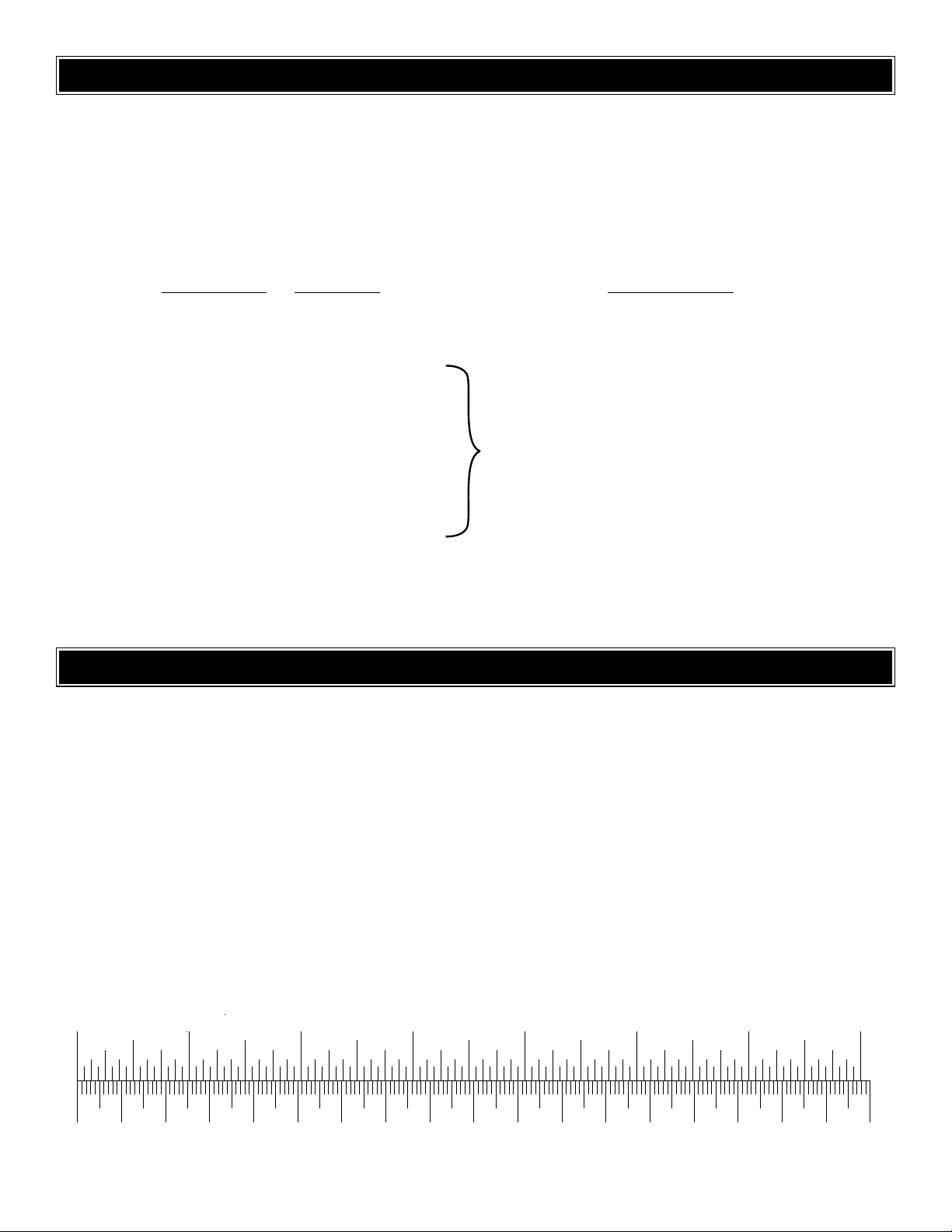
0" 1" 2" 3" 4" 5" 6" 7"
0 10 20 30 40 50 60 70 80 90 100 110 120 130 140 150 160 170 180
Inch Scale
Metric Scale
To convert inches to millimeters, multiply inches by 25.4
To order replacement par ts for the Great Planes DC-3 EP ARF, use the order numbers in the Replacement Parts List
that follows. Replacement parts are available only as listed. Not all par ts are available separately (an aileron cannot be
purchased separately, but is only available with the wing kit). Replacement parts are not available from Product Support,
but can be purchased from hobby shops or mail order/Internet order firms. Hardware items (screws, nuts, bolts) are also
available from these outlets. If you need assistance locating a dealer to purchase parts, visit www.greatplanes.com and
click on “Where to Buy.” If this kit is missing par ts, contact Product Support.
Replacement Parts List
Order Number Description How to Pur
chase
Missing pieces ................................................Contact Product Support
Instruction manual...........................................Contact Product Support
Full-size plans.................................................Not available
GPMA2590 ...........Fuse Kit
GPMA2591 ...........Wing Kit
GPMA2592 ...........Tail Set
GPMA2593 ...........Motors and Harness
GPMA2594 ...........ESC
GPMA2595 ...........Decal Sheet
GPMA2596 ...........Prop Set
GPMA2597 ...........Landing Gear
GPMA2598 ...........Cowls, Plastic Parts
ORDERING REPLACEMENT PARTS
Contact your hobby
supplier to purchase
these items.
1/64" = .4mm
1/32" = .8mm
1/16" = 1.6mm
3/32" = 2.4mm
1/8" = 3.2mm
5/32" = 4mm
3/16" = 4.8mm
1/4" = 6.4mm
3/8" = 9.5mm
1/2" = 12.7mm
5/8" = 15.9mm
3/4" = 19mm
1" = 25.4mm
2" = 50.8mm
3" = 76.2mm
6" = 152.4mm
12" = 304.8mm
15" = 381mm
18" = 457.2mm
21" = 533.4mm
24" = 609.6mm
30" = 762mm
36" = 914.4mm
METRIC CONVERSIONS
Page 7

Remove the major parts of the kit from the box (wings,
fuselage, tail parts, etc.) and inspect them for damage.If any
parts are damaged or missing, contact Product Suppor t at
the address or telephone number listed in this manual.
❏ 1. Where necessar y, use a covering iron with a covering
sock to tighten the covering that may have loosened during
storage. Apply pressure over sheeted areas to thoroughly
bond the covering to the wood.
❏ 2. Using a sharp hobby knife, cut the co vering a wa y in the
following areas on the top of the wing: wire outlets (4), L.E.
dowel hole (1), wing bolt holes (2).
❏ 3. Using a sharp hobby knife, cut the co vering a wa y in the
following areas on the bottom of the wing: wire outlets (2),
gear openings (2), wing bolt holes (2), servo openings (2)
(on left and right panels, not pictured).
❏ 4. There are two strings inside the wing center section
that have the ends taped to each root rib. Move the forward
string from the root rib and put it through the hole in the
bottom of the wing.Tape it to the wing as shown.
❏ 5. Use 6-minute epoxy to glue the four 3mm plywood
wing joiners together, making two pairs as shown in the
photo above. Use weights or clamps to hold the joiners in
place until the epoxy cures. Important: The joiners may be
marked with arrows to indicate which way is up and which
end points towards the tip. Be sure to orient the pieces as
shown in the photo. If your joiners are not marked with
arrows, mark them with a pencil.The wing tip end is narrower
(21mm) than the root end (23mm).
Assemble the Wing
BUILD THE WING
PREPARATIONS
7
Page 8

For the following steps start with the left wing panel
so your progress will match the photos.
❏❏6. Test fit the assembled wing joiner into the wing
panel, then the center section. Be certain the joiner is
installed upright with the arrow pointed up.The tapered end
with the horizontal arrow points toward the wing tip. Also
make sure that the joiner slides in all the way, allowing a
flush fit of the wing panel and the center section with no
gaps. If necessary, sand the joiner for a good fit.
❏❏7. Securely tie the strings for the aileron extensions
together as indicated in the above photo.
❏❏8. Remove the joiner. Using 30-minute epoxy,
thoroughly coat the inside of both pockets where the joiner
fits.Coat the joiner half that goes into the left wing panel.Then
insert the joiner into the left wing panel. Coat the protruding
end of the joiner, the root rib on the wing panel and the root
rib of the center section with epoxy. Join the left wing panel
and the center section together. Be sure to pull the strings
through as you slide the wing panel together with the center
section. Be careful not to get any epoxy on the strings.
❏❏9. Wipe away excess epoxy that squeezes out from
between the joint with paper towels saturated with alcohol.
Use masking tape on the top and bottom to hold the joint
tight as shown. Be cer tain the root ribs align accurately. Do
not disturb the wing until the epoxy has fully cured.
❏ 10. Repeat this process to glue the right wing panel in
place in the same manner.
❏ 1. Install the two motors onto the motor mount face
plates using the four supplied 2.5mm x 7.5mm screws and
2.5mm washers.
❏ 2. .This is a good time to test the motors. Do this before
installing the propellers. First make sure the transmitter and
ESC switches are turned OFF. Using the above picture,
connect the wires from the ESC to all of the labeled
components (motors, receiver, etc.). Switch on the
transmitter and make sure the throttle stick is at idle.Turn on
the ESC switch. Slowly advance the throttle stick to full
throttle. Move the throttle stick back to the idle position.The
system is now engaged and operational. Advance the
throttle stick and verify that both motors are working.
❏ 3. Tie the strings already installed in the wing onto the
connectors. Then place the wires into the center section
Mount the Motors
8
Page 9

directly behind the leading edge of the wing. Pull the wires
out of the center holes using the string as shown in the
above photo.The strings will help you guide the connectors
and wires through the holes in the wing ribs.
❏❏1. Trim the cowl par ts along the cut lines and mount
them into place.You have a number of options to complete
this;the method shown in the photos is to tape the cowls into
place using a clear tape.You can glue them if you wish, or
you can glue one portion such as the bottom half and tape
the remaining pieces.You could also mount them into place
with double-sided tape such as a good quality carpet tape.
❏❏2. Assemble the propeller shaft extension, propeller
and the propeller adapter as shown in the above photo.
Place the rubber propeller adapter into the propeller and
press it onto the shaft of the extension. Place the assembly
onto the motor shaft and secure it with two set screws on
each adapter.
Important: The rubber adapter must be placed on the
correct side of the prop. One side of the prop has a raised
flat area as shown in the photo above. The rubber adapter
must be inserted into this side.
❏❏1. Assemble the landing gear using the above photos
as a guide.Use (2) landing gear wires, (2) main LG adapters,
(6) 3mm set screws, (1) 3mm x 32mm axle, (2) plastic
spacers and (1) 51.5mm main wheel.Use threadlocker on all
the set screws.
Install the Landing Gear
Install the Motor Cowls
9
Page 10

❏❏2.After this assembly is completed, install it as shown
and secure it with a nylon landing gear strap and two
2.5mm x 11.5mm screws. Predr ill holes for the screws.Trim
the motor cowl as required.
❏ 3. Install the second landing gear in the same manner.
❏❏1. Test fit the aileron servos in the aileron servo
opening. If necessary, trim the opening in the wing to
accommodate the servo.
❏❏2.Connect a 12 inch extension to the servo lead wire and
secure with heat shrink tubing or tape.Inside the servo bay you
will find a string taped to the inside of the wing. Tie this string
securely to the servo extension connector and use the other
end of the string, in the wing center section, to pull it through.
Use the following photo for the next 3 steps.
❏❏3.Install the aileron servos using the grommets, brass
eyelets and screws supplied with the servos. Drill 1/16"
[1.6mm] holes for the screws; then screw them into place.
Remove the screws and harden the holes with a f e w drops of
thin CA.After the CA hardens, reinstall the servo and screws.
❏❏4. Mount the
nylon control horn
on the aileron with two
2mm x 16mm Phillips
head screws. Drill
5/64" [2mm] holes for
the screws.
❏❏5. Screw the clevis 12 full turns onto the 1.7mm x
99mm aileron pushrod. Attach the clevis to the aileron horn.
With the servo in the neutral position, use a felt-tip pen to
mark the pushrod where it crosses the hole in the servo arm.
Make a Z-bend in the pushrod at the mark. Cut the excess
pushrod off and use this to drill the hole in the servo arm.Slide
a silicone retainer over the clevis.
❏ 6. Return to step 1 and install the other aileron servo.
❏ 7. Join both aileron extensions into a “Y” connector.
❏ 1. Test fit the 5mm x 50mm dowel into the front of the
wing.The dowel should protrude approximately 3/8" [9.5mm].
When you are satisfied with the fit, glue it into place as shown
in the above photo.
Fit the Wing to the Fuselage
Install the Aileron Servos
10
Correct
Hinge Line
Incorrect
Page 11

❏ 2. Place the wing onto the fuselage and secure it in place
with two 4mm x 22mm wing bolts and 4mm flat washers.
Trial fit the wing fairing into place as shown.When satisfied
with the fit, glue the fairing into place using thin CA.
❏ 1. Locate the 1/8" [3.2mm] ply servo tray, aft former and
mid former. Glue the aft and mid formers to the servo tray
as shown above.
❏2.Locate the rear of the servo tray 12 inches from the nose
of the fuselage as shown in the photo above. Mark the
locations where the tray will be glued to the fuselage.Remove
the tray and sand the locations with 220-grit sandpaper .Clean
the area with a paper towel and rubbing alcohol. Glue the
servo tray into position with epoxy or medium CA.
❏ 3. Trial fit the battery tray into place as far forward as
possible in the nose of the fuselage.The tray should be 1-3/4"
[44.5mm] below the hatch opening at the rear edge. When
satisfied with the fit, glue the tray into place with epoxy.
Important: The battery tray should fit into the fuselage
without pushing the sides outwards. Carefully check that the
battery tray does not cause the fuselage sides to flex
outwards as it is inserted into place.Sand the sides of the tray
if necessary. If the sides flex outwards, the battery hatch will
not fit properly.
Install the Formers
ASSEMBLE THE FUSELAGE
IMPORTANT NOTES ABOUT
WORKING WITH FIBERGLASS
If you have never worked with fiberglass there are a few
basic things you should be aware of:
• When you are cutting into fiberglass, be sure you are
cutting the correct place. Unlike wood, you are not able to
go back and easily fix a mistake.
• Whenever y ou are gluing a part to the inside of fiberglass
it is important to roughen the inside surface of the fiberglass
with 220-grit sandpaper and then wipe the area with
rubbing alcohol. The molding process leaves a waxy
residue that can prevent a good bond between the glue and
the parts being glued.
Warning:The fuselage included in this kit is made of
fiberglass, the fibers of which may cause eye, skin
and respiratory tract irritation. Never blow into a part
to remove fiberglass dust, as the dust will blow back
into your eyes.Always wear safety goggles, a particle
mask and rubber gloves when grinding, drilling or
sanding fiberglass parts. Vacuum the parts and the
work area thoroughly after working with fiberglass.
11
Page 12

❏ 1. Using 220-grit sandpaper, sand or rough-up the outer
portion of the two pushrod outer plastic tubes. Locate the
nylon tie strap supplied in the parts bag and tie it
approximately 1/2 the length of the two pushrod outer tubes.
Insert the steel pushrods from the rear of the fuselage and
run them inside the two outer tubes. Note that these tubes
should be X’d at the nylon tie strap.
❏ 2.Work the outer tubes back and through the exit slots in
the rear of the fuselage.
❏ 3. Place the forward end of the tubes into the holes in the
servo tray as shown in the photo and glue them into place.Also
glue the outer tubes at the exit points at the rear of the fuselage.
❏ 4. Assemble the elevator and rudder servos as shown in
the above photo using the grommets, brass eyelets and
screws supplied with the servos. Install a screw lock
connector on each servo arm with a thumb nut with a drop
of thread lock.Note that the servo arms have been modified
so that only one arm remains.
❏ 5.Mount the two servos into the servo tra y in the manner
shown in the above photo.Temporarily place the push rods
into the screw lock connectors and tighten the set screws on
the top of the connectors.
❏ 1. Using a sharp hobby knife, cut the covering away from
both rudder hinge slots. Test fit the hinge points into the
Install the Tail Surfaces
Install the Servos
12
Page 13

rudder as illustrated in the above photo.When satisfied with
the fit and placement, glue the hinge points into place with
epoxy. Be careful not to get glue into the moving portion of
the hinges.
❏ 2. Trial fit the rudder into the fin.When satisfied with the
fit, glue the hinge points into the fin with epoxy. Be careful
not to get glue into the moving portion of the hinges.
❏ 3. Notice that the horizontal stab already has the covering
removed in the areas where it will be glued to the fuselage.
Insert the stab into the slots molded into the fuselage sides.
Use a tape measure or piece of string to verify that the stab
is positioned squarely into the fuselage. Measure the
distance from both ends of the stab to a marked location on
the front of the fuselage, moving the stab slightly until both
ends are the same distance.Mark the stab at the leading and
trailing edges with a fine tip marking pen. Remove the stab
from the fuselage. Do not glue the stab into place yet.
❏ 4. The two elevator halves are joined by the elevator
joiner. In order to install this joiner you first have to make
room for it by relie ving a small portion of the fuselage directly
behind the rear of the slot where the stab fits.To do this use
a rotary tool or a round file as shown in the above photo.
❏ 5. Next cut away the covering on each elevator half as
shown in the above photo. The elevators have been predrilled and pre-grooved to accept the joiner. Test fit the
elevator joiner wire in both elevator halves. Lay the elevator
halves on a flat surface and check that both are flat against
the surface.If one elevator half does not la y flat, the elevator
joiner wire may need to be twisted slightly.
❏ 6. Locate the four CA hinges and insert them into the two
elevator halves. Do not glue the hinges at this time.
13
Page 14

❏ 7. Insert the elevator joiner into place and hold it there
while sliding the stab into the slots.Do not glue anything into
place yet. We are test fitting everything first to make sure
that it fits correctly.
❏ 8. Slide the elevators into place using the joiner and
hinges. Everything should fit, match-up properly and move
freely. When you are satisfied with the alignments and fits,
remove the ele vators and doub le chec k that the alignment of
the stab is correct. Glue the stab into place by wicking thin
CA into the joint between the stab and fuselage. Fill any
gaps with medium CA.
❏ 9. Use thick CA or epoxy to glue the joiner into the
elevators, but be careful not to get any excess glue on the
stab or on the fuselage.When you have the elev ators in place
with no gaps between the stab and elevators , place six drops
of thin CA on both sides of each hinge and let it cure.Do not
use any accelerator while gluing the hinges into place.
❏ 10. Mount a nylon control horn on the elevator and the
rudder with two 2mm x 16mm Phillips head screws. Drill
5/64" [2mm] holes for the screws. Make sure the control
horns are aligned with the pushrods.
❏ 1. Place the two Velcro
®
battery straps into the forward
battery tray and test-fit the battery as shown in the above photo .
Review the next two steps before proceeding.
❏ 2. Put the piece of hatch mater ial inside the fuselage and
trace the hatch opening on the hatch. Cut the battery hatch
on the cut-lines you have drawn. Do this carefully to prevent
the hatch from chipping.Curved tip scissors work well f or this.
Install the Radio
14
Page 15

❏ 3. Using two fiberglass hatch strips and medium CA, glue
two of the strips onto the sides of the hatch as shown in the
photo. Note that the strips have been trimmed so that they
are 1/4" from the edges of the hatch. Be sure to sand the
areas to be glued and clean them with a paper towel and
rubbing alcohol.
❏ 4. Using two fiberglass hatch strips and medium CA, glue
two of the strips onto the fuselage as shown in the photo.
❏ 5.The hatch is installed in the fuselage by squeezing the
sides and catching the side strips along the sides of the
fuselage opening. The two strips glued onto the fuselage
maintain the curvature of the hatch while the two pieces on
the hatch hold it in the opening. When complete the hatch
should fit evenly and securely.Small pieces of clear tape can
also be used on the leading and trailing edge of the hatch to
hold it more securely.
❏ 6. Install the tail gear wire onto the fuselage using two
2.5mm x 9.5mm flanged Phillips head screws as shown in
the photo above. Drill 1/16" [1.6mm] pilot holes for the
screws.Harden the holes with thin CA.
❏ 7. Mount the 25mm tail wheel with a 2mm wheel collar
and set screw.
❏ 8. Finalize the installation of the radio system by
mounting the speed control and the mini-receiver in the
fuselage with hook and loop strips as shown in the photo
above. Plug the servos and speed control into the receiver.
Use a 6" [153mm] servo extension wire for the aileron servo .
❏ 9. Mount the switch through the fuselage side as shown
❏ 10. Route the receiver antenna through the fuselage side
or bottom using a strain relief. Secure the antenna at the
rear of the fuselage with a piece of clear tape.
❏ 1. Use scissors or a sharp hobby knife to cut the decals
from the sheet.
❏ 2. Be certain the model is clean and free from oily
fingerprints and dust. Prepare a dishpan or small bucket with
a mixture of liquid dish soap and warm water–about one
teaspoon of soap per gallon of water.Submerse the decal in
the soap and water and peel off the paper backing. Note:
Apply the Decals
15
Page 16

Even though the decals hav e a “sticky-back”and are not the
water transfer type , submersing them in soap & water allo ws
accurate positioning and reduces air bubbles underneath.
❏ 3. Position each decal on the model where desired.
Holding the decal down, use a paper towel to wipe most of
the water away.
❏ 4. Use a piece of soft balsa or something similar to
squeegee any remaining water from under the decal. Apply
the rest of the decals the same way.
❏ 5. Cut a piece of leftover clear decal material 1" x 1-1/2"
[25.4 x 38mm].Apply this to the bottom of the fuselage nose
to protect it should the model nose-over on landing.
❏ 1. Turn on the transmitter and receiver and center the
trims. If necessar y, remove the servo arms from the servos
and reposition them so they are centered. Reinstall the
servo arms and screws that hold on the servo arms.
❏ 2. While the transmitter and receiver are still on, check all
the control surfaces to see if they are centered.If necessary ,
adjust the clevises or screw-lock connectors on the
pushrods to center the control surfaces.
❏ 3. Make certain that the control surfaces respond in the
correct direction as shown in the diagram. If any of the
controls respond in the wrong direction, use the servo
reversing in the transmitter to reverse the servos connected
to those controls. Be certain the control surfaces have
remained centered. Adjust if necessary.
Use a Great Planes AccuThrow™(or a ruler) to accurately
measure and set the control throw of each control surface as
indicated in the chart that follows.If your radio does not have
dual rates, we recommend setting the throws at the low rate
setting. NOTE: The throws are measured at the widest part
of the elevators, rudder and ailerons.
IMPORTANT: The Great Planes DC-3 EP ARF has been
extensively flown and tested to arrive at the throws at
which it flies best. Flying your model at these throws will
provide you with the greatest chance for successful first
flights. If, after you have become accustomed to the way
the DC-3 EP ARF flies, you would like to change the
throws to suit your taste that is fine. However, too much
control throw could make the model difficult to control, so
remember, “More is not always better.”
These are the recommended control surface throws:
High Rate Low Rate
ELEVATOR: 7/16" [11mm] up 5/16" [8mm] up
3/8" [9.5mm] down 1/4" [6mm] down
AILERONS: 7/16" [11mm] up 5/16" [8mm] up
7/16" [11mm] down 5/16" [8mm] down
RUDDER: 1" [25.4mm] right 1" [25.4mm] right
1" [25.4mm] left 1" [25.4mm] left
Set the Control Throws
CAUTION: To prevent an accident, remove the props
and prop adapters before connecting the motor battery.
Check the Control Directions
GET THE MODEL READY TO FLY
16
4-CHANNEL RADIO SETUP
(STANDARD MODE 2)
4-CHANNEL
TRANSMITTER
ELEVATOR MOVES UP
4-CHANNEL
TRANSMITTER
RIGHT AILERON MOVES UP
LEFT AILERON MOVES DOWN
RUDDER MOVES RIGHT
CARBURETOR WIDE OPEN
4-CHANNEL
TRANSMITTER
4-CHANNEL
TRANSMITTER
Page 17

At this stage the model should be in ready-to-fly condition
with all of the systems in place including the motors, landing
gear, complete radio system, and 8-cell battery.
❏ 1. Use a felt-tip pen or 1/8"-wide tape to accurately mark
the C.G.on the top of the wing on both sides of the fuselage.
The C.G. is located 2-7/16" [62mm] back from the
leading edge of the wing.
❏ 2. With the wing attached to the fuselage, all parts of the
model installed (ready to fly), place the model upside-down
on a Great Planes CG Machine, or lift it upside down at the
balance point you marked.
❏ 3. If the tail drops, the model is “tail heavy” and the
battery pack and/or receiver must be shifted forward or
weight must be added to the nose to balance. If the nose
drops, the model is “nose heavy” and the battery pack
and/or receiver must be shifted aft or weight must be added
to the tail to balance. If possible, relocate the battery pack
and receiver to minimize or eliminate any additional ballast
required. If additional weight is required, nose weight may
be easily added by using Great Planes (GPMQ4485) “stick
on” lead. A good place to add stick-on nose weight is to the
inside of the nose section of the fuselage. Begin by placing
incrementally increasing amounts of weight on the bottom of
the fuse over the nose until the model balances. Once you
have determined the amount of weight required, it can be
permanently attached. If required, tail weight may be added
and glued permanently inside the fuselage.
Note: Do not rely upon the adhesive on the back of the lead
weight to permanently hold it in place. Use #2 sheet metal
screws, RTV silicone or epoxy to permanently hold the
weight in place.
❏ 4. IMPORTANT: If you found it necessary to add any
weight, recheck the C.G.after the weight has been installed.
❏ 1. With the wing level, have an assistant help you lift the
model by the engine propeller shaft and the bottom of the
fuse under the TE of the fin.Do this several times.
❏2.If one wing always drops when you lift the model, it means
that side is heavy. Balance the airplane by adding weight to the
other wing tip. An airplane that has been laterally balanced
will track better in loops and other maneuvers.
No matter if you fly at an AMA sanctioned R/C club site or if
you fly somewhere on your o wn, you should alw a ys hav e y our
name, address, telephone number and AMA number on or
inside your model. It is required at all AMA R/C club flying
sites and AMA sanctioned flying events. Fill out the
identification tag on the back cover and place it in y our model.
Follow the battery charging instructions that came with your
radio control system to charge the batteries. You should
always charge your transmitter batteries the night before
you go flying and at other times as recommended by the
radio manufacturer.
Charge the Batteries
Identify Y our Model
PREFLIGHT
Balance the Model Laterally
This is where your model should balance for the first
flights. Later, you may wish to experiment by shifting the
C.G. up to 2-5/16" [59mm] forward or 2-3/4" [70mm] back
to change the flying characteristics. Moving the C.G.
forward ma y impro v e the smoothness and stability, but the
model may then require more speed for takeoff and make
it more difficult to slow for landing. Moving the C.G. aft
makes the model more maneuverable, but could also
cause it to become too difficult to control. In any case,
start at the recommended balance point and do not at
any time balance the model outside the specified range.
More than any other factor, the C.G. (balance point) can
have the greatest effect on how a model flies and may
determine whether or not your first flight will be
successful. If you value this model and wish to enjoy it for
many flights, DO NOT OVERLOOK THIS IMPORTANT
PROCEDURE. A model that is not properly balanced will
be unstable and possibly unflyable.
Balance the Model (C.G.)
17
Page 18

Before you fly you should perform one last overall inspection
to make sure the model is truly ready to fly and that you
haven’t ov erlooked anything.If you are not thoroughly familiar
with the operation of R/C models, ask an experienced
modeler to perform the inspection. Check to see that you
have the radio installed correctly and that all the controls are
connected properly. The motors must also be checked by
confirming that the props are rotating in the correct direction
and the motors sound like they are reaching full power. Make
certain all control surfaces (elevators, rudder, ailerons) are
secure, the pushrods are connected, the controls respond in
the correct direction, radio components are securely
mounted and the C.G.is correct.
Ground check the operational range of your r adio before the
first flight of the day. With the transmitter antenna collapsed
and the receiver and transmitter on, you should be able to
walk at least 100 feet away from the model and still have
control. Have an assistant stand by your model and, while
you work the controls, tell you what the control surfaces are
doing. Repeat this test with the motors running at various
speeds with an assistant holding the model, using hand
signals to show you what is happening. If the control
surfaces do not respond correctly, do not fly! Find and
correct the problem first.Look for loose servo connections or
broken wires, corroded wires on old servo connectors, poor
solder joints in your battery pack or a defective cell, or a
damaged receiver crystal from a previous crash.
• Get help from an experienced pilot when learning to
operate motors.
• Use safety glasses when starting or running motors.
• Do not run the motors in an area of loose gravel or sand;
the propellers may throw such material in your face or eyes.
• Keep your face and body as well as all spectators away
from the plane of rotation of the propellers as you start and
run the motors.
• Keep these items away from the props: loose clothing,
shirt sleeves, ties, scarfs, long hair or loose objects such as
pencils or screwdrivers that may fall out of shirt or jacket
pockets into the props.
• The motors get hot! Do not touch them during or right
after operation.
• The electric motors and battery used in your DC-3 EP
ARF are very powerful and the spinning propellers have a lot
of momentum; therefore, if you touch a propeller while it is
spinning it may inflict severe injury. Respect the motors and
propellers for the damage they are capable of and take
whatever precautions are necessary to avoid injury. Always
disconnect and remove the battery until you are ready to fly
again and always make sure the switches are turned off
before connecting the battery.
Read and abide by the following Academy of Model
Aeronautics Official Safety Code:
1. I will not fly my model aircraft in sanctioned events, air
shows, or model flying demonstrations until it has been
proven to be airworthy by ha ving been pre viously successfully
flight tested.
2. I will not fly my model aircraft higher than approximately
400 feet within 3 miles of an airport without notifying the
airpor t operator. I will give right of way to and avoid flying in
the proximity of full scale aircraft. Where necessary an
observer shall be used to supervise flying to avoid having
models fly in the proximity of full scale aircraft.
3. Where established, I will abide by the safety rules for the
flying site I use and I will not willfully and deliberately fly my
models in a careless, reckless and/or dangerous manner.
7. I will not fly my model unless it is identified with my name
and address or AMA number, on or in the model.
9. I will not operate models with pyrotechnics (any device
that explodes, burns, or propels a projectile of any kind).
1.I will have completed a successful radio equipment ground
check before the first flight of a new or repaired model.
2. I will not fly my model aircraft in the presence of
spectators until I become a qualified flier, unless assisted b y
an experienced helper.
3. I will perform my initial turn after takeoff away from the pit
or spectator areas and I will not thereafter fly over pit or
spectator areas, unless beyond my control.
4. I will operate my model using only radio control frequencies
currently allowed by the F ederal Communications Commission.
Radio Control
General
AMA SAFETY CODE (
EXCERPT
)
Failure to follow these safety precautions may result
in severe injury to yourself and others.
MOTOR SAFETY PRECAUTIONS
Range Check
Ground Check
18
Page 19

❏ 1. Check the C.G. according to the measurements
provided in the manual.
❏ 2. Be certain the battery and receiver are securely
mounted in the fuse.
❏ 3. Extend your receiver antenna and make sure it has a
strain relief inside the fuselage to keep tension off the solder
joint inside the receiver.
❏ 4. Balance your model
laterally
as explained in
the instructions.
❏ 5. Use threadlocking compound to secure critical
fasteners such as the set screws that hold the wheel axles
to the struts, screw-lock pushrod connectors, etc.
❏ 6.Add a drop of oil to the axles so the wheels will turn freely .
❏ 7. Make sure all hinges are securely glued in place.
❏ 8. Reinforce holes for wood screws with thin CA
where appropriate (servo mounting screws, cowl mounting
screws, etc.).
❏ 9. Confirm that all controls operate in the correct
direction and the throws are set up according to the manual.
❏ 10 Make sure that all servo arms are secured to the
servos with the screws included with your radio.
❏ 11. Secure connections between servo wires and
Y-connectors or servo extensions and the connection between
your battery pack and the on/off switch with vinyl tape, heat
shrink tubing or special clips suitable for that purpose.
❏ 12. Make sure any servo extension cords you may have
used do not interfere with other systems (servo arms,
pushrods, etc.).
❏ 13. Place your name, address, AMA number and
telephone number on or inside your model.
❏ 14. If you wish to photograph your model, do so before
your first flight.
❏ 15. Range check your radio when you get to the flying field.
The Great Planes DC-3 EP ARF is a great-flying model that
flies smoothly and predictably. The Great Planes DC-3 EP
ARF does not, however, possess the self-recovery
characteristics of a primary R/C trainer and should be flown
only by experienced R/C pilots.
If you are not used to using the rudder to coordinate turns,
this is one model where you should start doing so. The
DC-3 EP has a large wingspan with a relatively short
fuselage. As a result, the adverse yaw produced when the
ailerons alone are used to turn is much more pronounced
than you may be accustomed to. In addition, the increased
drag caused by the adverse yaw will slow the model and
cause the nose to drop slightly. Using coordinated rudder
(right rudder with right aileron) will give much cleaner and
better looking turns. Of course, this is a good control
technique for any model.
Due to the small wheel size of the DC-3 EP, rise off ground
(ROG) takeoffs are only possible from a smooth surface. If
you are flying from a grass field, the DC-3 EP can be safely
and easily hand-launched. Do not attempt to do so by
yourself. Have an assistant launch the model in a level or
slightly nose high attitude, with the wings level. It is not
necessary to throw the model into the air.Simply take a few
steps while gently pushing the model into the air. Allow the
model to accelerate before climbing or turning. Always
launch the model into the wind.
Before you get ready to takeoff, see how the model handles
on the ground by doing a fe w pr actice runs at low speeds on
the runway. Hold “up” elevator to keep the tail wheel on the
ground. If necessary, adjust the tail wheel so the model will
roll straight down the runway.
Takeoff
CAUTION (THIS APPLIES TO ALL R/C AIRPLANES): If,
while flying, you notice an alarming or unusual sound
such as a low-pitched “buzz,” this may indicate control
surface flutter .Flutter occurs when a control surface (such
as an aileron or elevator) or a flying surface (such as a
wing or stab) rapidly vibrates up and down (thus causing
the noise). In extreme cases, if not detected immediately,
flutter can actually cause the control surface to detach or
the flying surface to fail, thus causing loss of control
followed by an impending crash. The best thing to do
when flutter is detected is to slow the model immediately
by reducing power, then land as soon as safely possible.
Identify which surface fluttered (so the problem may be
resolved) by checking all the servo grommets for
deterioration or signs of vibration. Make certain all
pushrod linkages are secure and free of play. If it fluttered
once, under similar circumstances it will probably flutter
again unless the problem is fixed.Some things which can
cause flutter are; Excessive hinge gap; Not mounting
control horns solidly; Poor fit of clevis pin in horn; Sideplay of wire pushrods caused by large bends; Excessive
free play in servo gears; Insecure servo mounting; and
one of the most prevalent causes of flutter;Flying an overpowered model at excessive speeds.
FLYING
During the last few moments of preparation your mind may
be elsewhere anticipating the excitement of the first flight.
Because of this, you may be more likely to overlook certain
checks and procedures that should be performed before
the model is flown.T o help a void this , a checklist is pro vided
to make sure these important areas are not overlooked.
Many are covered in the instruction manual, so where
appropriate, refer to the manual for complete instructions.
Be sure to check the items off as they are completed.
CHECKLIST
19
Page 20

Remember to takeoff into the wind.When you’re ready, point
the model straight down the runway, hold a bit of up elevator
to keep the tail on the ground, then gradually advance the
throttle. As the model gains speed decrease up elevator
allowing the tail to come off the ground. One of the most
important things to remember with a tail dragger is to always
be ready to apply right rudder to counteract motor torque.
Gain as much speed as your runway and flying site will
practically allow before gently applying up ele v ator , lifting the
model into the air. At this moment it is likely that you will
need to apply more right rudder to counteract motor torque.
Be smooth on the elevator stick, allowing the model to
establish a gentle climb to a safe altitude before turning into
the traffic pattern.
For reassurance and to keep an eye on other traffic, it is a
good idea to have an assistant on the flight line with you.Tell
him to remind you to throttle back once the plane gets to a
comfortable altitude.While full throttle is usually desirable for
takeoff, most models fly more smoothly at reduced speeds.
Take it easy with the Great Planes DC-3 EP ARF for the first
few flights, gradually getting acquainted with it as you gain
confidence. Adjust the trims to maintain straight and level
flight. After flying around for a while and while still at a safe
altitude with plenty of battery charge, practice slow flight and
execute pr actice landing approaches by reducing the throttle
to see how the model handles at slower speeds.Add power
to see how she climbs as well. Continue to fly around,
executing various maneuvers and making mental notes (or
having your assistant write them down) of what trim or C.G.
changes may be required to fine tune the model so it flies
the way you like.Mind your battery charge level, but use this
first flight to become familiar with your model bef ore landing.
If you are flying from a grass field you must use some care
when landing. Attempt to land in the smoothest part of the
field.You should also tr y to land at a slow flying speed, but
not so slowly that the model stalls.This model does not slow
rapidly on final approach, so a low “dragged-in” approach
may be needed. Always land into the wind. Due to the
small wheel size the model may start to nose over .Gradually
applying up elevator after the model has landed will
minimize this.
To initiate a landing approach, lower the throttle while on the
downwind leg. Allow the nose of the model to pitch
downward to gradually bleed off altitude. Continue to lose
altitude, but maintain airspeed by k eeping the nose down as
you turn onto the crosswind leg.Make your final turn toward
the runway (into the wind), using coordinated aileron and
rudder control, keeping the nose down to maintain airspeed
and control. Level the attitude when the model reaches the
runway threshold, modulating the throttle as necessary to
maintain your glide path and airspeed. If you are going to
overshoot, smoothly advance the throttle (always ready on
the right rudder to counteract torque) and gently climb out to
make another attempt. When you’re ready to make your
landing flare and the model is a foot or so off the deck,
smoothly increase up elevator until it gently touches down.
Once the model is on the runway and has lost flying speed,
hold up elevator to place the tail on the ground.
One final note about flying your model. Have a goal or flight
plan in mind for every flight. This can be learning a new
maneuver(s), improving a maneuver(s) y ou already kno w, or
learning how the model behaves in certain conditions (such
as on high or low rates). This is not necessar ily to improve
your skills (though it is never a bad idea!), but more
importantly so you do not surprise yourself by impulsively
attempting a maneuver and suddenly finding that you’ve run
out of time, altitude or airspeed. Every maneuver should be
deliberate, not impulsive.For example, if you’re going to do
a loop, check your altitude, mind the wind direction
(anticipating rudder corrections that will be required to
maintain heading), remember to throttle back at the top and
make certain you are on the desired rates (high/low rates).
A flight plan greatly reduces the chances of crashing your
model just because of poor planning and impulsive moves.
Remember to think.
Have a ball!
But always stay in control and fly in a safe manner.
GOOD LUCK AND GREAT FLYING!
Landing
Flight
 Loading...