

Page 1
WARRANTY
Great Planes®Model Manufacturing Co. guarantees this kit to be free from defects in both material and workmanship at the date of purchase. This warranty
does not cover any component parts damaged by use or modification. In no case shall Great Planes’ liability exceed the original cost of the purchased kit.
Further, Great Planes reserves the right to change or modify this warranty without notice.
In that Great Planes has no control over the final assembly or material used for final assemb ly, no liability shall be assumed nor accepted for any damage resulting
from the use by the user of the final user-assembled product.By the act of using the user-assembled product, the user accepts all resulting liability.
If the buyer is not prepared to accept the liability associated with the use of this product,the buyer is advised to return this kit immediatel y in new and
unused condition to the place of purchase.
To make a warranty claim send the defective part or item to Hobby Services at the address below:
Hobby Services
3002 N. Apollo Dr. Suite 1
Champaign IL 61822
USA
Include a letter stating your name, return shipping address, as much contact information as possible (daytime telephone number, fax number, e-mail address), a
detailed description of the problem and a photocopy of the purchase receipt. Upon receipt of the package the problem will be eva luated as quickly as possible.
READ THROUGH THIS MANUAL BEFORE STARTING
CONSTRUCTION.IT CONT AINS IMPORTANT INSTRUCTIONS
AND WARNINGS CONCERNING THE ASSEMBLY AND
USE OF THIS MODEL.
GPMZ0252 for GPMA1153 V1.0 Entire Contents © Copyright 2004
Champaign, IL
(217) 398-8970, Ext. 5
airsupport@greatplanes.com
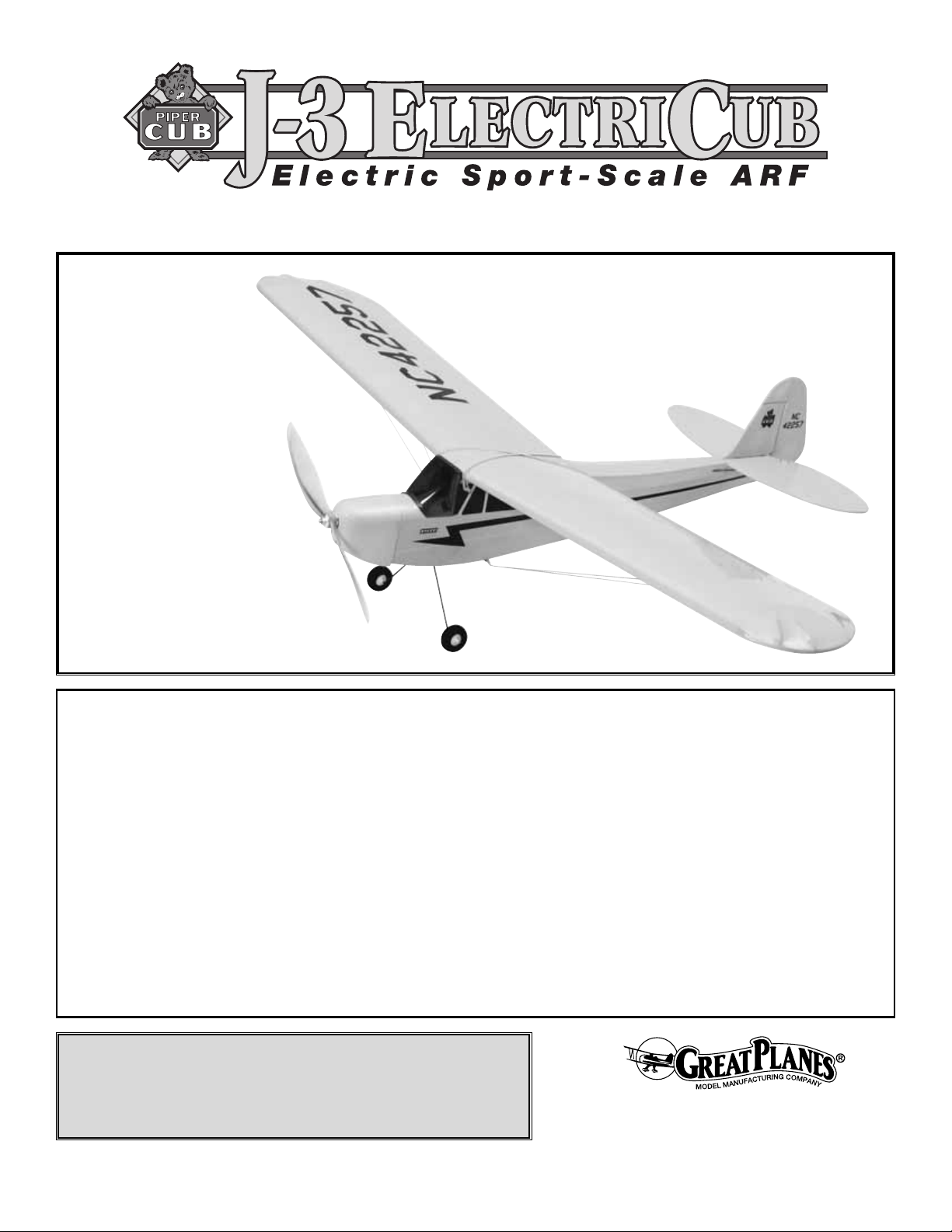
INSTRUCTION MANUAL
Wingspan: 41 in [1040mm]
Wing Area: 269 sq in [17.4 dm
2
]
Weight: 10 oz [285g]
Wing Loading: 7.5 oz/sq ft [23 g/dm
2
]
Length: 29.5 in [750mm]
Radio: 3-channel with 2 sub-micro servos
Motor: T-280-size with 3.5:1 gear box
Motor Battery: 9.6V – 650 mAh
Page 2
INTRODUCTION.................................................................................2
AMA....................................................................................................2
SAFETY PRECAUTIONS...................................................................2
DECISIONS YOU MUST MAKE.........................................................3
Radio Equipment.........................................................................3
Battery Selection.........................................................................3
Chargers......................................................................................4
ADDITIONAL ITEMS REQUIRED......................................................4
Adhesives & Building Supplies....................................................4
Optional Supplies & Tools ...........................................................4
IMPORTANT BUILDING NOTES .......................................................4
COMMON ABBREVIATIONS.............................................................5
ORDERING REPLACEMENT PARTS ...............................................5
KIT CONTENTS .................................................................................6
METRIC/INCH RULER.......................................................................6
BUILDING INSTRUCTIONS...............................................................7
Preparations................................................................................7
Join the Wing...............................................................................7
Install the Landing Gear..............................................................7
Install the Tail Skid & Wing Braces..............................................8
Assemble the Tail........................................................................9
Install the Windscreen ...............................................................10
Pushrod Installation...................................................................10
Mount the Servos......................................................................10
Mount the Motor........................................................................11
Install the Cowl ..........................................................................11
Optional: Install the Wing Struts................................................11
GET THE MODEL READY TO FLY ..................................................12
Final Radio Hook Up.................................................................12
Check the Control Directions ....................................................13
Set the Control Throws..............................................................13
Propeller Installation..................................................................14
Balance the Model (C.G.)..........................................................14
Balance the Model Laterally......................................................14
PREFLIGHT......................................................................................15
Identify Y our Model....................................................................15
Charge the Batteries.................................................................15
Balance the Propellers..............................................................15
Ground Check...........................................................................15
Range Check.............................................................................15
Mount the Wing.........................................................................15
MOTOR SAFETY PRECAUTIONS ..................................................16
AMA SAFETY CODE (excerpt).......................................................16
General......................................................................................16
Radio Control ............................................................................16
CHECK LIST ....................................................................................17
FLYING .............................................................................................17
Takeoff.......................................................................................17
Flight..........................................................................................17
Landing......................................................................................18
The Mini Cub ARF is a true park flyer, able to fly in small
areas (but not intended for indoor settings). It is a great
second airplane, with 6+ minutes of flight time on the stock
motor package recommended, and climbs with authority to
do mild aerobatics such as loops and stall turns.
For the latest technical updates or manual corrections to the
Great Planes Mini Cub ARF, visit the Great Planes web site
at
www.greatplanes.com
. Open the “Airplanes” link, and
then select the Great Planes Mini Cub ARF. If there is new
technical information or changes to this model a “tech
notice” box will appear in the upper left corner of the page.
We urge you to join the AMA (Academy of Model
Aeronautics) and a local R/C club. The AMA is the
governing body of model aviation and membership is
required to fly at AMA clubs. Though joining the AMA
provides many benefits, one of the primary reasons to join
is liability protection. Coverage is not limited to flying at
contests or on the club field. It even applies to flying at
public demonstrations and air shows.F ailure to comply with
the
AMA Safety Code
(excerpts printed in the back of the
manual) may endanger insurance coverage. Additionally,
training programs and instructors are available at AMA club
sites to help you get started the right way. There are over
2,500 AMA chartered clubs across the countr y.Contact the
AMA at the address or toll-free phone number below:
IMPORTANT! Two of the most important things you can do
to preserve the radio controlled aircraft hobby are to avoid
flying near full-scale aircraft and avoid flying near or over
groups of people.
CAUTION: Be aware that the Mini Cub ARF is operated
on the same frequency band as larger, “regular” R/C
models. If flying your Mini Cub ARF within 5 miles of an
R/C site, there is a real possibility that you could be
operating your model on the same frequency (channel)
as another R/C pilot. If this happens, a crash will
result–with the person flying the more expensive model
suffering the greater loss and the potential for property
damage or injury.) The best thing to do is to join an R/C
club and fly at the site where frequency control measures
will be in effect. If you insist on flying elsewhere
always be aware of your proximity to R/C fl ying sites.
PRO TECT YOUR MODEL,Y OURSELF
& OTHERS...FOLLOW THESE
IMPORTANT SAFETY PRECAUTIONS
Academy of Model Aeronautics
5151 East Memorial Drive
Muncie, IN 47302
Tele: (800) 435-9262
Fax (765) 741-0057
Or via the Internet at:
http://www.modelaircraft.org
AMA
INTRODUCTION
TABLE OF CONTENTS
2
Page 3

Attention: The product you have purchased is powered by
a rechargeable battery. At the end of its useful life, under
various state and local laws, it may be illegal to dispose of
this battery into the municipal waste system. Check with
your local solid waste officials for details in your area for
recycling options or proper disposal.
This product contains a chemical known to the state of
California to cause cancer and birth defects or other
reproductive harm.
1. Even though the Mini Cub ARF is small, lightweight and
flies slowly, if it is not assembled and operated correctly, it
could possibly cause injury to yourself or spectators and
property damage.
2. You must assemble the model according to the
instructions. Do not alter or modify the model, as doing so
may result in an unsafe or unflyable model.
3.You must take time to build straight, true and strong.
4. You must use an R/C radio system that is in first-class
condition; a correctly sized motor and components (servos,
battery, etc...) throughout the building process; and a micro
speed control capable of handling 5 Amps.
5.You must correctly install all R/C and other components
so that the model operates correctly on the ground and in
the air.
6.You must check the operation of the model before every
flight to insure that all equipment is operating and that the
model has remained structurally sound. Be sure to check
clevises or other connectors often and replace them if they
show any signs of wear or fatigue.
7. If you are not an experienced pilot or have not flown this
type of model before, we recommend that you get the
assistance of an experienced pilot in your R/C club for your
first flights. If you’re not a member of a club, your local
hobby shop has information about clubs in your area whose
membership includes experienced pilots.
Remember:Take your time and follow the instructions to
end up with a well-built model that is straight and true.
This is a partial list of items required to finish the Great
Planes Mini Cub ARF that may require planning or decision
making before starting to build.Order numbers are provided
in parentheses.
The Mini Cub ARF requires a micro receiver and two Nano
servos. Futaba®S3107 (FUTM0037) or Hobbico®CS-5
(HCAM0090) micro servos are suitable. A 3-channel radio
is also required. The Great Planes C-5 (GPMM2000) hifrequency speed control is required.
There are mainly two kinds of battery packs used for
electric R/C models; nickel-metal hydride (NiMH) packs and
nickel-cadmium (NiCd, pronounced ny-cad) packs. NiMH
batteries are recommended for the Mini Cub ARF because
they provide nearly twice the capacity of a NiCd for their
size.However, it should be noted that nickel-metal hydrides
cannot be charged as fast as NiCds.
Each individual cell that makes up a battery is 1.2 volts.
Simply stated, a volt is the amount of power a battery pack
can deliver (a 6-cell battery pack is 7.2 volts). Batteries are
also rated by their capacity in mAh (milli-Amp-hours), or how
much energy they store. A 550 mAh battery can supply 1
Ampere for .55 hours (about 30 minutes).A 1200 mAh battery
pack is about twice the size of a 550 mAh battery pack.
The battery pack recommended for the Mini Cub ARF:
• GPMP0072 8-cell 9.6V 2/3AA 650 NiMH
Battery Selection
Radio Equipment
DECISIONS YOU MUST MAKE
Note: We, as the kit manufacturer , provide you with a top
quality, thoroughly tested kit and instructions, but
ultimately the quality and flyability of your finished model
depends on how you build it;therefore, we cannot in any
way guarantee the performance of your completed
model, and no representations are expressed or implied
as to the performance or safety of your completed model.
3
Page 4
Note:
Depending on battery choice, you may have to
remove the cross brace in the battery compartment to allow
the battery pack to fit. This does not adversely affect the
performance of the Mini Cub ARF.
The best type of charger to use is a peak charger, because
it charges the batteries until they are fully charged, then
automatically switches to a trickle charge mode.The Great
Planes ElectriFly Peak Charger (GPMM3000) is suitable for
nickel-metal hydride batteries, NiCds and transmitter
battery packs.
If you have another type of charger that is not a peak charger,
you will have to calculate the length of time it takes to charge
the batteries yourself, then turn the charger off when the
batteries are fully charged. Overcharging the batteries can
damage them. Before you can calculate the time it takes to
charge a battery pack, you first must know the charge rate you
are going to use. Nickel-metal hydrides must be charged at a
rate of no more than 1/10 of their capacity. For the 650 mAh
batteries recommended for the Mini Cub ARF this would be a
charge rate of approximately 65 mAh. Divide the capacity of
the battery pack by the charge rate to calculate the charge
time. A discharged 650 mAh battery pack charged at 0.65
mAh will take 10 hours to charge.
IMPORTANT: Monitor the temperature of the battery
frequently. If the battery becomes warm, disconnect it from
the charger.
A Great Planes ElectriFly DC Peak 400 Charger
(GPMM3001) is also suitable for charging the battery packs
used in the Mini Cub ARF.
Note: The period required to charge the battery in the
example is for a fully discharged battery. If the battery you
are going to charge is not discharged (and you are not
using a peak-charger), connect it to the motor on your
model.Run the motor until the auto cutoff on the ESC stops
the motor.
In addition to common household tools and hobby tools, this
is the “short list” of the most important items required to
build the Mini Cub ARF.
Great Planes Pro™CA and Epoxy
glue are recommended.
❏ Hobby knife (HCAR0105)
❏ #11 blades (HCAR0211)
❏ Small T-pins (HCAR5100)
❏ Electric drill and 1/16" [1.6mm] drill bit
❏ Small Phillips and flat blade screwdrivers
❏ Pliers with wire cutter (HCAR0630)
❏ 1/2 oz.Thin Pro CA (GPMR6001)
❏ 6-Minute Epoxy (GPMR6045)
❏ 30-Minute Epoxy (GPMR6047)
❏ R/C-56 Canopy glue (JOZR5007)
❏ Non-elastic monofilament or Kevlar
®
fishing line (for
stab alignment)
❏ Builder’s Tr iangle Set (HCAR0480) (for fin alignment)
❏ Thread Locking Compound
Here is a list of optional tools mentioned in the manual that
will help you build the Mini Cub ARF.
❏ Great Planes CG Machine
™
(GPMR2400)
❏ Straightedge with scale (HCAR0475)
❏ Top Flite
®
MonoKote®sealing iron (TOPR2100)
❏ Top Flite MonoKote trim seal iron (TOPR2200)
❏ Masking tape (TOPR8018)
❏ CA accelerator (GPMR6034)
❏ Mixing sticks (GPMR8055)
❏ Denatured alcohol (for epoxy clean up)
❏ Curved-tip canopy scissors (HCAR0667)
❏ Clear packing tape
• When you see the term
test fit
in the instructions, it
means that you should first position the part on the
assembly without using any glue, then slightly modify or
custom fit
the part as necessar y for the best fit.
• Whenever the term
glue
is written you should rely upon
your experience to decide what type of glue to use.When a
specific type of adhesive works best for that step, the
instructions will make a recommendation.
• Whenever just
epoxy
is specified you may use either
30-minute (or 45-minute) epoxy or 6-minute epoxy. When
30-minute epoxy is specified it is highly recommended that
you use only 30-minute (or 45-minute) epoxy, because you
will need the working time and/or the additional strength.
•
Photos
and
sketches
are placed before the step they
refer to. Frequently you can study photos in following steps
to get another view of the same parts.
• The Mini Cub ARF is factory-covered with Top Flite
MonoKote film. Should repairs ever be required, MonoKote
film can be patched with additional MonoKote film purchased
separately. MonoKote film is packaged in six-foot rolls, but
IMPORTANT BUILDING NOTES
Optional Supplies & Tools
Adhesives & Building Supplies
ADDITIONAL ITEMS REQUIRED
Chargers
4
Page 5
some hobby shops also sell it by the f oot.If only a small piece
of MonoKote film is needed f or a minor patch, perhaps a fellow
modeler would give you some. MonoKote film is applied with
a model airplane covering iron, but in an emergency a regular
clothing iron could be used. A roll of MonoKote film includes
full instructions for application. Following is the color used on
this model and the order number for a six foot roll.
Cub Yellow – TOPQ0220
• The stabilizer and wing incidences and motor thrust
angles have been f actory-built into this model.Howe ver, some
technically minded modelers may wish to check these
measurements anyway.To view this information, visit the web
site at
www.greatplanes.com
and click on “Technical Data.”
Due to manufacturing tolerances which will have little or no
effect on the way your model will fly, please expect slight
deviations between your model and the published values.
Fuse = Fuselage
Stab = Horizontal Stabilizer
Fin = Vertical Fin
LE = Leading Edge
TE = Trailing Edge
LG = Landing Gear
" = Inches
mm = millimeters
COMMON ABBREVIATIONS
5
Replacement parts for the Great Planes Mini Cub ARF are available using the order numbers in the Replacement Parts List that
follows.The fastest, most economical service can be provided by your hobby dealer or mail-order company. Parts may also be ordered
directly from Hobby Services, but full retail prices and shipping and handling charges will apply. Illinois and Nevada residents will also
be charged sales tax.
To locate a hobby dealer, visit the Hobbico web site at
www
.hobbico.com
. Choose “Where to Buy” at the bottom of the menu on
the left side of the page.Follow the instructions provided on the page to locate a U .S., Canadian or International dealer.If a hobby shop
is not available, replacement parts may also be ordered from Tower Hobbies at
www
.towerhobbies.com
, or by calling toll free
(800) 637-6050, or from Hobby Services by calling (217) 398-0007, or via facsimile at (217) 398-7721.If ordering via fax, include a Visa
or MasterCard number and expiration date for payment.
Mail parts orders and payments by personal check or money order to:Hobby Services, 3002 N Apollo Drive, Suite 1, Champaign, IL, 61822
Be certain to specify the order number exactly as listed in the Replacement Parts List. Payment by credit card or personal check
only; no C.O.D.
If additional assistance is required for any reason, contact Product Support by e-mail at
productsupport@greatplanes.com
, or by
telephone at (217) 398-8970.
Replacement Parts List
Order Number
Description How to Purchase
Missing pieces.......................Contact Product Support
Instruction manual.................Contact Product Support
Full-size plans........................Not available
GPMA2640 Wing Set
GPMA2641 Fuselage
GPMA2642 Tail Set
GPMA2643 Cowl
GPMA2644 Windscreen
GPMA2645 Landing Gear
GPMA2646 Gear Drive
GPMA2647 Speed Control
GPMA2648 Motor
GPMA2649 Propeller
ORDERING REPLACEMENT PARTS
................
Contact Your Hobby
Supplier to Purchase
These Items
Page 6
6
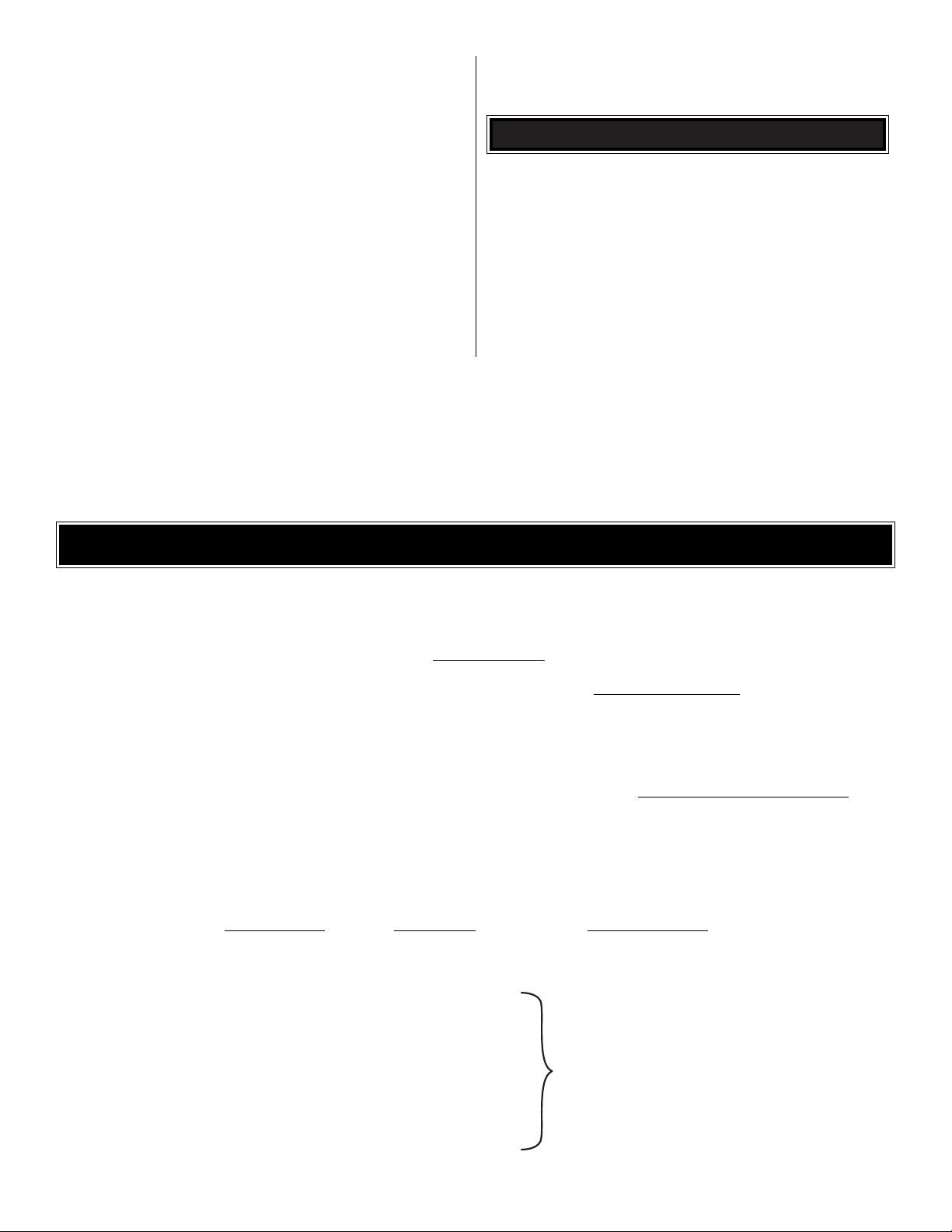
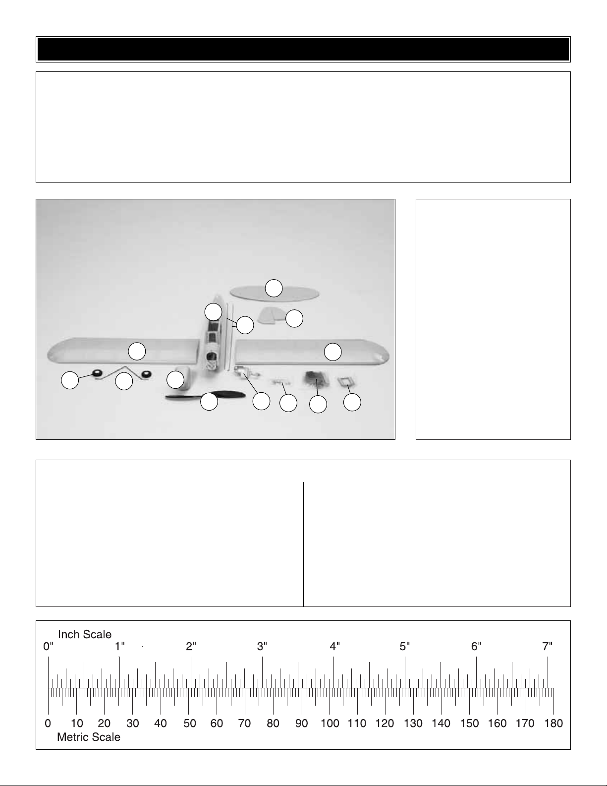
Kit Contents
1. L and R Wing Panels
2. Fuselage
3. Stab and Elevator
4. Fin and Rudder
5. Landing Gear
6. Wheels (2)
7. Propeller
8. Cowl
9. Motor
10. Hardware Bag
11. Parts Bag
12. Servo Tray
13. Pushrods (2)
Kit Contents (not photographed)
(1) Tail Skid
(2) Wing Dowel Rods
(2) Nylon Control Horns with Back Plates
(4) 2 x 10mm Machine Screws
(1) Wooden Landing Gear Brace
(4) 2 x 5mm Washer Head Self- Tapping Screws
(1) 2 x 8mm Washer Head Self- Tapping Screw
(1) Battery Cover Latch
(2) 2 x 6mm Round Head Self-Tapping Screws
(2) Knurled Nuts
(2) Quick Connect Posts
(2) 2.8 x 5mm Machine Screws
(1) Electronic Speed Control
(2) Nylon Tie Straps
Before starting to build, take an inventory of this kit to make sure it is complete, and inspect the parts to make sure they are of
acceptable quality. If any parts are missing or are not of acceptable quality, or if you need assistance with assembly, contact
Great Planes Product Support. When repor ting defective or missing parts, use the part names exactly as they are written in
the Kit Contents list on this page.
Great Planes Product Support:
Telephone: (217) 398-8970, ext. 5
Fax: (217) 398-7721
E-mail:
airsupport@greatplanes.com
KIT CONTENTS
To convert inches to millimeters, multiply inches by 25.4
1
1
2
4
5
7
8
3
11
10
13
6
9
12
Page 7

❏ 1. If you have not done so already, remove the major
parts of the kit from the box (wing halves, fuselage, tail
parts, etc…) and inspect them for damage. If any parts are
damaged or missing, contact Product Support at the
address or telephone number listed on page 6.
❏ 2. With a covering sock on your covering iron, set the
temperature to medium and tighten the covering. If
necessary, apply pressure to the sheeted areas to
thoroughly bond the covering to the wood.Hint: Poke three
or four pin holes in the covering between the ribs in the tail
surfaces;this will allow the hot air to escape when tightening
the covering.
❏ 1. Glue the wing joiners together using 6-minute epoxy
and allow them to harden. Test fit the wing joiner into the
slots in the wing halves.Sand the joiner as required to get a
tight, secure fit that allows the wing panels to mate as nicely
as possible. Note: If the root ribs’ angles aren’t exactly the
same, that’s OK. The difference can be filled with epoxy
when the wings are joined.
❏ 2. Cover your workbench with wax paper.
❏ 3. With the left wing flat on your workbench and the
center joint on the wax paper, raise the right wing tip 3-3/4"
[95mm] to properly set the dihedral. Block the raised right
wing at the desired height and make a mental note of the
position needed for it to maintain that dihedral.Slide the left
wing and joiner off the right wing.
❏ 4. Remove the joiner from the left wing. Cover the joiner,
left and right wing root ribs and pockets in the wing panels
with a moderate, but not excessive, amount of 30-minute
epoxy. Join the wing halves together. Ensure that the left
wing remains flat and the right wing tip is 3-3/4" [95mm]
from your workbench and can remain that way undisturbed
until the epoxy hardens.Hint: Use masking tape to hold the
wing together while the epoxy cures. Remove any excess
epoxy prior to hardening with a paper towel dampened with
denatured alcohol, being careful not to disturb the joint.
❏ 1. Push one plastic wheel collar on each axle, leaving
approximately 3/32" [2mm] between the wheel collar and
the bend.
❏ 2.Slide the wheels onto the axles and hold them in place
with the two remaining wheel collars.Make sure the wheels
spin freely.
Install the Landing Gear
Join the Wing
Preparations
BUILDING INSTRUCTIONS
7
Page 8

❏ 3. Remove the covering from the landing gear slot in the
bottom of the fuse located just in front of the battery hatch.
❏ 4. Fit the landing gear into the fuse and test fit the
plywood triangle block. Lock the gear in place by gluing the
plywood triangle in the landing gear slot with CA.
❏ 1. Place the fuselage upside-down on the workbench
and cut the covering away from the two holes for installing
the tail skid. Remove a small strip of covering from between
the two holes and securely glue the tail skid in place.
❏ 2. Locate and cut out the four holes to the front and rear of
the wing saddle for the dowel rods. Insert the wing dowels in
the holes and center. When centered, securely glue them in
place using a few drops of thin CA.
❏ 3. Temporarily install the battery cover. Drill a 1/16"
[1.6mm] hole approximately 1/8" [3mm] in front of the
battery compartment, closest to the landing gear.Attach the
battery cover latch to the fuse, using the supplied
2.5 x 8mm self-tapping screw. Do not overtighten; the latch
must be able to move, but not freely.
❏ 4.Carefully remove the cov ering from the battery cooling
holes on the battery cover with a sharp hobby knife.
Install the Tail Skid & Wing Braces
8
Page 9

❏ 1. Center and align the LE of the horizontal stab with the
centerline of the fuse. Pin the front center of the stab to the
centerline of the fuse.
❏ 2. Locate the center stringer running the length of the fuse
on the top.This is the centerline of the fuse. Attach one end of
a piece of string to the centerline using a T-pin or piece of
masking tape, just behind the wing saddle, and extend the
string to the left outer edge of the stabilizer.Mark the string at
that location on a piece of tape. Move the end of the string to
the other side of the stab.Rotate the stab until both lengths are
the same. Pin the TE of the stab to the fuse.
❏ 3.Using a fine point felt-tip pen, mark the covering on the
bottom of the stab where it contacts the fuse.
❏ 4. Remove the stab. Cut the covering from the marked
area of the stab and from the gap on the front of the stab.
Note: Be careful not to cut into the balsa stab when
removing the covering.
❏ 5. Mount the wing to the fuse with two of the rubber
bands included with this kit. Pin the stab to the fuse; check
from behind the aircraft to make sure the stab is parallel with
the wing. Lift the stab off, and coat the stab where the
covering was removed and the fuselage with 30-min epoxy.
Reinstall the stab with the pin for guidance.
❏ 6.Center the fin on the stab and align it with the center of the
fuse.The front of the fin will slide into a notch in the front of the
horizontal stab. Mark the stab on both sides of the base of the
fin.Remove the covering from the marked area of the top of the
stab and the bottom of the fin. Note: Be careful not to cut into
the balsa stab when removing the covering.
❏ 7. Using 30-min epoxy, glue the fin to the stab, making
sure to keep it aligned with the centerline of the fuse and
perpendicular to the stab until the glue is fully cured.
Assemble the Tail
9
Page 10

❏ 1. Locate the trim line on the windscreen; it will be a small
recessed area showing where to cut for the proper shape.Cut
the windscreen a little at a time on this line with sharp scissors,
or canopy scissors.Test fit the windscreen often and trim it as
necessary. When you are happy with the fit, glue it in place
using canopy glue. Clear tape may be used as well, as
desired. Note: Do not use CA, it will fog the plastic.
❏ 1. Connect the wire pushrod to the second-from-the-
outer hole in a nylon control horn.You may have to enlarge
the hole in the horn using a sharp hobby knife.
❏ 2. Locate the pushrod exit tubes at the tail end of the
fuselage. They are located just forward of the horizontal
stab. If you cannot see them, feel for the slight indentation
through the covering or insert the pushrod into the pushrod
tubes inside the fuselage, and push the pushrods against
the covering. Cut the covering away from the pushrod exit
with a sharp hobby knife.
❏ 3.Slide the straight end of the pushrods into the fuselage
from the tail.
❏ 4.Position the control horn so that the pushrod mounting
holes are aligned with the hinge line. Mark the location of
the control horns’ mounting holes on to the elevator and
rudder control surface. Drill two 1/16" [1.6mm] holes where
you marked them.
❏ 5. Using the 2 x 10mm machine screws provided, attach
the nylon control horn and tighten with the nylon back plate.
Be careful not to crush the wood when tightening.
❏ 1.T est fit the servo tray as shown in the photo, but do not
glue it in place.This will allow you to move the tray forward
or aft to assist with the balancing of the model.
Mount the Servos
Pushrod Installation
Install the Windscreen
10
Page 11

❏ 2.Attach a screw-lock pushrod connector on the servo arm
that came with the servo. Inser t the threaded portion down
through the top of the arm, slide a washer on the bottom of the
threaded portion and tighten to the horn using the small
knurled nut. Be sure to apply a small drop of thread locking
compound to the threaded portion to prevent the nut from
working loose and falling off. Do not overtighten as the
connector must be able to rotate freely.Do this for both servos.
❏ 3.Fit the two servos in the servo tray as shown.Plug the
servos and ESC into your receiver. Tur n on the transmitter
and receiver to center the servos. Slide the pushrods
through the screw-lock pushrod connectors, but do not
tighten. Drill 1/16" [1.6mm] pilot holes in the tray where the
servo mounting holes line up.Making sure not to preload the
pushrods, mount the servos to the servo tray with the
hardware provided with your radio. Turn the transmitter and
receiver off.Don’t cut the pushrods yet.This will allow you to
adjust the position of the servo tray for balancing.
❏ 1.Following the motor manuf acturer’ s instructions, assemb le
your motor and gear box. Refer to the
“Motor”
section on
page 3.
❏ 2.Test fit the motor in the motor mount.The motor should
be as far back as possible, without contacting the firewall.
When satisfied with the fit, secure the motor with the
supplied zip-tie straps.
❏ 1. Cut the 1/2" [13mm] circle from the front of the cowl and
the small square below it as shown using a sharp hobby knife .
❏ 2. Test fit the cowl and trim as necessary.
❏ 3. Attach the cowling to the fuselage with clear tape.We
used clear packing tape to secure the cowling to the fuse.
Note: Two pieces of yellow string are provided to simulate
wing struts. They enhance the appearance of the plane, but
are not necessary.The plane can be flown without the struts.
❏ 1. Through the covering on the bottom of the wing you
should be able to see four small black dots, two on each
side, between the second and third ribs from the wing tips.
Optional: Install the Wing Struts
Install the Cowl
Mount the Motor
11
Page 12
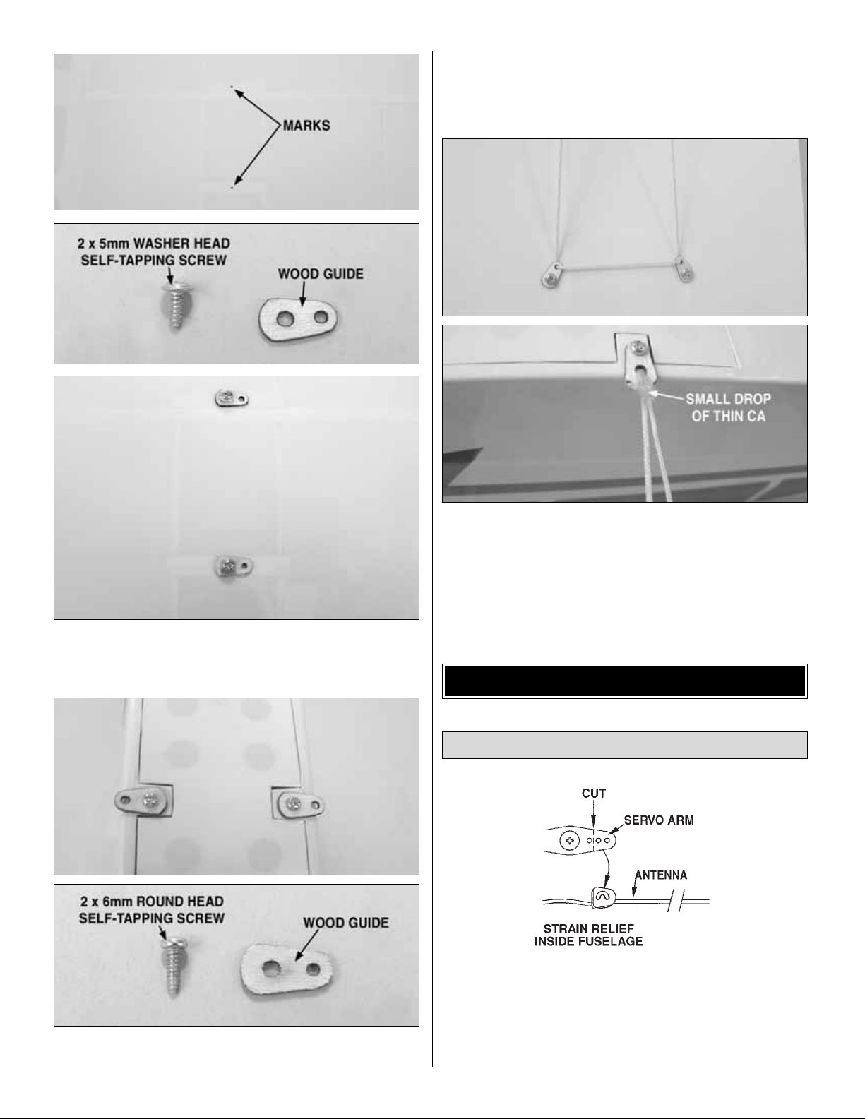
❏ 2.Drill a 1/16" [1.6mm] hole on each mark and attach the
plywood guides using two 2 x 5mm washer head self-tapping
screws shown in the photo. Do this for both sides.
❏ 3. On each side of the battery compar tment, center and
drill a 1/16" [1.6mm] hole and attach the remaining two
guides using the two remaining 2 x 6mm round-head
self-tapping screws.
❏ 4. Attach the wing to the fuse using rubber bands.
❏ 5. Use the included yellow thread to make the wing
struts. Take one length of thread and run it through both
guides on one side of the wing. Then tie the ends to the
guide installed on the fuse. Add a small drop of CA to the
knot to secure it.Do this for both sides.Removal of the wing
can be accomplished by unscrewing the two guides from
the bottom of the fuse.
❏ 1.Complete the radio installation by connecting the ESC
and servos to the receiver.The receiver antenna should be
run out of and taped to the bottom of the fuselage. Do not
cut off the excess antenna;let it hang from the aft end of the
fuselage. Be sure to provide a strain relief for the receiver
antenna as shown.
Final Radio Hook Up
GET THE MODEL READY TO FLY
12
Page 13

❏ 2.Turn on the transmitter and receiver.Double-check that
the elevator trim on your transmitter is centered, the servo
arm on the servo is centered and that the elevator is
centered to the stab.
❏ 3. Double-check that the rudder trim is centered on your
transmitter, the servo arm on the servo is centered and that
the rudder is centered on the fin.
❏ 4. Insert and tighten 2.8 x 5mm machine screws on the
screw-lock pushrod connectors to clamp down on the
pushrods and trim off excess pushrod with wire cutters.
Leave approximately 1/2" [13mm] beyond the screw-lock
pushrod connector.
❏ 1. Turn on the transmitter and receiver and center the
trims. If necessary, remove the servo arms from the ser vos
and reposition them so they are centered. Reinstall the
screws that hold on the servo arms.
❏ 2. With the transmitter and receiver still on, check all the
control surfaces to see if they are centered. If necessary,
adjust the screw-lock pushrod connectors on the pushrods
to center the control surfaces.
❏ 3. Make certain that the control surfaces respond in the
correct direction as shown in the diagram. If any of the
controls respond in the wrong direction, use the servo
reversing in the transmitter to reverse the servos connected
to those controls. Be certain the control surfaces have
remained centered. Adjust if necessary.
Use a Great Planes AccuThrow™(or a ruler) to accurately
measure and set the control throw of each control surface
as indicated in the chart that follows. If your radio does not
have dual rates, we recommend setting the throws at the
low rate setting.
Note: The throws are measured at the widest part of the
elevator and rudder.
IMPORTANT: The Mini Cub ARF has been extensively
flown and tested to arrive at the throws at which it flies
best. Flying your model at these throws will provide you
with the greatest chance for successful first flights.If, after
you have become accustomed to the way the Mini Cub
ARF flies, you would like to change the thro ws to suit y our
taste, that is fine. However, too much control throw could
make the model difficult to control, so remember , “more is
not always better.”
These are the recommended control surface throws:
High Rate Low Rate
ELEVATOR: 5/8" [16mm] up 1/2" [13mm] up
5/8" [16mm] down 1/2" [13mm] down
RUDDER: 5/8" [16mm] right 3/8" [10mm] right
5/8" [16mm] left 3/8" [10mm] left
Set the Control Throws
Check the Control Directions
13
Page 14

Prior to balancing the model install the propeller.
The servo tray and receiver location are used to adjust the
center of gravity (C.G.). For now, temporarily position the
battery in the battery compartment and receiver in the radio
compartment, but do not secure them in place.When setting
the C.G. (below), adjust the position of the receiver and
servo tray as needed. Remember to also reposition the
Velcro® and rubber band mounting to properly hold them in
place. Note: Once the Mini Cub ARF is balanced, you may
secure the receiver and glue the servo tray in place.
❏ 1.Use a felt-tip pen or 1/8" [3mm] wide tape to accurately
mark the C.G.on the bottom of the wing on both sides close
to the fuselage. The recommended C.G. is located 2-1/16"
[52mm] back from the leading edge of the wing.
❏ 2.With the wing attached to the fuselage and all parts of
the model installed (ready-to-fly), place the model on a
Great Planes C.G. Machine™, or lift it at the balance point
you marked.
❏ 3. If the tail drops, the model is “tail heavy” and the
battery pack and/or receiver must be shifted forward or
weight must be added to the nose to balance. If the nose
drops, the model is “nose heavy” and the battery pack
and/or receiver must be shifted aft or weight must be added
to the tail to balance. If possible, relocate the battery pack
and receiver to minimize or eliminate any additional ballast
required. Use Great Planes (GPMQ4485) “stick-on” lead if
necessary to add weight. A good place to add stick-on nose
weight is to the firewall (don’t attach weight to the cowl–it is
not intended to support weight). Begin by placing
incrementally increasing amounts of weight on the bottom of
the fuse over the firew all until the model balances.Once you
have determined the amount of weight required, it can be
permanently attached. If required, tail weight may be added
under the stabilizer.
❏ 4. IMPORTANT: If you found it necessary to add any
weight, recheck the C.G.after the weight has been installed.
❏ 1. With the wing level, lift the model by the motor
propeller shaft and the bottom of the fuse under the TE of
the fin. Do this several times.
❏ 2.If one wing always drops when y ou lift the model, it means
that side is heavy. Balance the airplane by adding weight to the
other wing tip.An air plane that has been laterally balanced will
track better in loops and other maneuvers.
At this stage the model should be in ready-to-fly condition
with all of the systems in place including the motor, landing
gear, cover ing and paint, and the radio system.
Balance the Model Laterally
This is where your model should balance for the first
flights. Later, you may wish to experiment by shifting the
C.G. up to 1/4" [6.4mm] forward or 1/4" [6.4mm] back to
change the flying characteristics.Moving the C.G.forward
may improve the smoothness and stability, but the model
may then require more speed for takeoff and make it
more difficult to slow for landing. Moving the C.G. aft
makes the model more maneuverable, but could also
cause it to become too difficult to control. In any case,
start at the recommended balance point and do not at
any time balance the model outside the specified range.
More than any other factor, the C.G. (balance point) can
have the greatest effect on how a model flies, and may
determine whether or not your first flight will be
successful. If you value this model and wish to enjoy it for
many flights, DO NOT OVERLOOK THIS IMPORTANT
PROCEDURE. A model that is not proper ly balanced will
be unstable and possibly unflyable.
Balance the Model (C.G.)
Propeller Installation
14
Page 15

No matter if you fly at an AMA sanctioned R/C club site or if
you fly somewhere on your own, you should always have
your name, address, telephone number and AMA number
on or inside your model. It is required at all AMA R/C club
flying sites and AMA sanctioned flying events. Fill out the
identification tag on page 18 of this manual and place it on
or inside your model.
Follow the battery charging instructions that came with your
radio control system to charge the batteries. You should
always charge your transmitter and receiver batteries the
night before you go flying, and at other times as
recommended by the radio manufacturer.
Note: All battery packs, whether it’ s a trusty pac k you’v e just
taken out of another model, or a new battery pack you just
purchased, should be cycled, noting the discharge capacity.
Oftentimes, a weak battery pack can be identified (and a
valuable model saved!) by comparing its actual capacity to
its rated capacity. Refer to the instructions and
recommendations that come with your cycler. If you don’t
own a battery cycler, perhaps you can have a friend cycle
your pack and note the capacity for you.
Carefully balance your propeller and spare propellers before
you fly. An unbalanced prop can be the single most significant
cause of vibration that can damage your model.For electric
motors, proper balance is even more critical than glow
motors. Not only will pushrod connector screws loosen,
possibly with disastrous effect, but vibration may also
damage your radio receiver and speed control.
We use a Top Flite Precision Magnetic Prop Balancer
™
(TOPQ5700) in the workshop and keep a Great Planes
Fingertip Prop Balancer (GPMQ5000) in our flight box.
If the motor is new, follow the manufacturer’s instructions to
break-in the motor. After you run the motor on the model,
inspect the model closely to make sure all screws remained
tight, the hinges are secure, the prop is secure and all
pushrods and connectors are secure.
Ground check the operational range of your r adio bef ore the
first flight of the day. With the transmitter antenna collapsed
and the receiver and transmitter on, you should be able to
walk at least 100' awa y from the model and still hav e control.
Have an assistant stand by your model and, while you work
the controls, tell you what the control surfaces are doing.
Repeat this test with the motor running at various speeds
with an assistant holding the model, using hand signals to
show you what is happening. If the control surfaces do not
respond correctly, do not fly! Find and correct the problem
first. Look for loose servo connections or broken wires,
corroded wires on old servo connectors, poor solder joints
in your battery pack or a defective cell, or a damaged
receiver crystal from a previous crash.
Mount the wing to the fuselage with rubber bands included
with the Mini Cub ARF. Install them from front to back,
crisscrossing the last two.Never use torn or cracked rubber
bands. After removing the rubber bands from your model,
store them in a container with talcum powder or clay-type
kitty litter to keep them fresh for the next flying session. Use
eight (8) #32 Great Planes, Hobbico or similar rubber bands
as replacements.
If the rubber bands you will be using are different from those
recommended, consult an experienced modeler to make
certain they are strong enough, and that you have used
enough of them. If uncertain, force the front of the wing off
of the wing saddle. There should be considerable
resistance! If the wing can be forced from the fuselage
without having to strain your hands, then there are probably
not enough rubber bands.
Mount the Wing
Range Check
Ground Check
Balance the Propellers
CAUTION: Unless the instructions that came with your
radio system state differently, the initial charge on new
transmitter and receiver batteries should be done for 15
hours using the slow-charger that came with the radio
system.This will “condition”the batteries so that the next
charge may be done using the fast-charger of your
choice. If the initial charge is done with a fast-charger the
batteries may not reach their full capacity and you may be
flying with batteries that are only partially charged.
Charge the Batteries
Identify Y our Model
PREFLIGHT
15
Page 16

The Mini Cub ARF is a great-flying model that flies smoothly
and predictably. The Mini Cub ARF does not, however,
possess the self-recovery characteristics of a primary R/C
trainer and should be flown only by experienced R/C pilots.
1. Do not run the motor in an area of loose gravel or sand;
the propeller may throw such material in your face or eyes.
2. Keep your face and body as well as all spectators away
from the plane of rotation of the propeller at all times that the
motor is armed.
3.Keep these items awa y from the prop:loose clothing, shirt
sleeves, ties, scarves, long hair or loose objects such as
pencils or screwdrivers that may fall out of shir t or jacket
pockets into the prop.
4. The motor gets hot! So does the battery pack and the
ESC. Do not touch it during or r ight after operation.
5. REMEMBER! This is an electric motor. Unlike a glow
engine, it can start at any time without any movement of the
prop by the user. ALWAYS take extreme care around your
electric motor.
6. Do not use hands, fingers, or any other body part to try
and stop the motor.Do not throw anything into the propeller
of a running motor.
Read and abide by the following e xcerpts from the Academy
of Model Aeronautics Safety Code.For the complete Safety
Code refer to
Model Aviation
magazine, the AMA web site
or the Code that came with your AMA license.
GENERAL
1) I will not fly my model aircraft in sanctioned events, air
shows, or model flying demonstrations until it has been
proven to be airworthy by having been previously,
successfully flight tested.
2) I will not fly my model aircraft higher than approximately
400 feet within 3 miles of an airport without notifying the
airpor t operator. I will give right-of-way to and avoid flying in
the proximity of full-scale aircraft. Where necessary, an
observer shall be utilized to supervise flying to avoid having
models fly in the proximity of full-scale aircraft.
3) Where established, I will abide by the safety rules for the
flying site I use, and I will not willfully and deliberately fly my
model in a careless, reckless and/or dangerous manner.
5) I will not fly my model unless it is identified with my name
and address or AMA number, on or in the model.Note: This
does not apply to models while being flown indoors.
7) I will not operate models with pyrotechnics (any device
that explodes, burns, or propels a projectile of any kind).
RADIO CONTROL
1) I will have completed a successful radio equipment ground
check before the first flight of a new or repaired model.
2) I will not fly my model aircraft in the presence of
spectators until I become a qualified flier, unless assisted b y
an experienced helper.
3) At all flying sites a straight or curved line(s) must be
established in front of which all flying takes place with the
AMA SAFETY CODE (excerpt)
Failure to follow these safety precautions may result
in severe injury to yourself and others.
MOTOR SAFETY PRECAUTIONS
CAUTION (THIS APPLIES TO ALL R/C AIRPLANES): If,
while flying, you notice an alarming or unusual sound
such as a low-pitched “buzz,” this may indicate control
surface
flutter
. Flutter occurs when a control surface
(such as an aileron or elevator) or a flying surface (such
as a wing or stab) rapidly vibrates up and down (thus
causing the noise). In extreme cases, if not detected
immediately, flutter can actually cause the control surface
to detach or the flying surface to fail, thus causing loss of
control followed by an impending crash.The best thing to
do when flutter is detected is to slow the model
immediately by reducing power, then land as soon as
safely possible. Identify which surface fluttered (so the
problem may be resolved) by checking all the servo
grommets for deterioration or signs of vibration. Make
certain all pushrod linkages are secure and free of play. If
it fluttered once, under similar circumstances it will
probably flutter again unless the problem is fixed. Some
things which can cause flutter are; Excessive hinge gap;
Not mounting control horns solidly; Poor fit of clevis pin in
horn; Side-play of wire pushrods caused by large bends;
Excessive free play in servo gears; Insecure servo
mounting;and one of the most prevalent causes of flutter;
Flying an over-powered model at excessive speeds.
IMPORTANT! Flying a model with too few rubber bands
can be dangerous. If the wing momentarily lifts from the
fuselage and acts as though a large amount of “up”
elevator has suddenly been applied because there are
not enough rubber bands or they are too weak, internal
structural damage may result.Even worse, the wing could
actually detach from the fuselage resulting in a crash. If
the model exhibits any tendencies that indicate there are
not enough rubber bands, immediately reduce power,
land and closely inspect the model for damage. If no
damage is found, add more rubber bands.
16
Page 17

other side for spectators.Only personnel involved with flying
the aircraft are allowed at or in the front of the flight line.
Intentional flying behind the flight line is prohibited.
4) I will operate my model using only radio control frequencies
currently allowed by the F ederal Comm unications Commission.
5) I will not knowingly operate my model within three
miles of any pre-existing flying site except in
accordance with the frequency sharing agreement
listed (see the complete AMA Safety Code).
9) Under no circumstances may a pilot or other person
touch a powered model in flight;nor should any part of the
model other than the landing gear intentionally touch
the ground, except while landing.
❏ 1. Check the C.G. according to the measurements
provided in the manual.
❏ 2. Be certain the battery and receiver are securely
mounted in the fuse.Simply stuffing them into place
with foam rubber is not sufficient.
❏ 3. Extend your receiver antenna and make sure it has
a strain relief inside the fuselage to keep tension off
the solder joint inside the receiver.
❏ 4. Balance your model
laterally
as explained in
the instructions.
❏ 5. Use thread locking compound to secure critical
fasteners such as the set screws that hold the
screw-lock pushrod connectors, etc.
❏ 6. Add a drop of oil to the axles so the wheels will
turn freely.
❏ 7. Make sure all hinges are securely glued in place.
❏ 8. Confirm that all controls operate in the correct
direction and the throws are set up according to
the manual.
❏ 9. Make sure that all servo arms are secured to the
servos with the screws included with your radio.
❏ 10. Make sure any servo extension cords you ma y ha v e
used do not interfere with other systems (servo
arms, pushrods, etc.).
❏ 11. Balance your propeller (and spare propellers).
❏ 12. Tighten the propeller nut.
❏ 13. Place your name, address, AMA number and
telephone number on or inside your model.
❏ 14. Cycle your plane’s battery pack (if necessary) and
make sure it is fully charged.
❏ 15. If you wish to photograph your model, do so before
your first flight.
❏ 16. Range check your radio when y ou get to the flying field.
Before you get ready to take off, see how the model handles
on the ground by doing a few practice r uns at low speeds on
the runway. Hold “up” elevator to keep the tail skid on the
ground. If you need to calm your nerves before the maiden
flight, turn off the motor and bring the model back into the pits.
Remember to take off into the wind. When you’re ready,
point the model straight down the runway, then gradually
advance the throttle.As the model gains speed decrease up
elevator allowing the tail to come off the ground. One of the
most important things to remember with a tail dragger is to
always be ready to apply right rudder to counteract motor
torque. Gain as much speed as your runway and flying site
will practically allow before gently applying up elevator,
lifting the model into the air. At this moment it is likely that
you will need to apply more right rudder to counteract motor
torque. Be smooth on the elevator stick, allowing the model
to establish a gentle climb to a safe altitude before turning
into the traffic pattern.The Mini Cub ARF may also be hand
launched if your site does not have a runway or you prefer
hand launching.
For reassurance and to keep an e y e on other traffic , it is a good
idea to have an assistant on the flight line with you.Tell him to
remind you to throttle back once the plane gets to a comf ortable
altitude. While full throttle is usually desirable for takeoff, most
models fly more smoothly at reduced speeds.
Take it easy with the Mini Cub ARF for the first few flights,
gradually getting acquainted with it as you gain confidence.
Adjust the trims to maintain straight and level flight. After
flying around for a while, and while still at a safe altitude,
practice slow flight and ex ecute practice landing approaches
by reducing the throttle to see how the model handles at
slower speeds. Add power to see how she climbs as well.
Continue to fly around, executing various maneuvers and
making mental notes (or having your assistant write them
down) of what trim or C.G.changes may be required to fine
tune the model so it flies the way you like. Use this first flight
to become familiar with your model but keep it relatively
short so you have plenty of battery power to take a few
practice passes at landing.
Flight
Takeoff
FLYING
During the last few moments of preparation your mind
may be elsewhere anticipating the excitement of the first
flight. Because of this, you may be more likely to overlook
certain checks and procedures that should be performed
before the model is flown.To help avoid this, a check list
is provided to make sure these important areas are not
overlooked. Many are covered in the instruction manual
so, where appropriate, refer to the manual for complete
instructions. Be sure to check the items off as they are
completed (that’s why it’s called a
check list!
).
CHECK LIST
17
Page 18

To initiate a landing approach, lower the throttle while on the
downwind leg. Allow the nose of the model to pitch
downward to gradually bleed off altitude. Continue to lose
altitude, but maintain airspeed by k eeping the nose do wn as
you turn onto the crosswind leg.Make your final turn toward
the runway (into the wind) keeping the nose down to
maintain airspeed and control. Level the attitude when the
model reaches the runway threshold, modulating the throttle
as necessary to maintain your glide path and airspeed. If
you are going to overshoot, smoothly advance the throttle
(always ready on the right rudder to counteract torque) and
climb out to make another attempt. When you’re ready to
make your landing flare and the model is a foot or so off the
deck, smoothly increase up elevator until it gently touches
down. Once the model is on the runway and has lost flying
speed, hold up elevator to place the tail on the ground.
One final note about flying your model.Have a goal or flight
plan in mind for every flight. This can be learning a new
maneuver(s), improving a maneuver(s) y ou already know, or
learning how the model behaves in certain conditions (such
as on high or low rates).This is not necessarily to improve
your skills
(though it is never a bad idea!)
, but more
importantly so you do not surprise yourself by impulsively
attempting a maneuver and suddenly finding that you’v e run
out of time, altitude or airspeed. Every maneuver should be
deliberate, not impulsive.For example, if you’re going to do
a loop, check your altitude, mind the wind direction
(anticipating rudder corrections that will be required to
maintain heading), remember to throttle back at the top, and
make certain you are on the desired rates (high/low rates).
A flight plan greatly reduces the chances of crashing your
model just because of poor planning and impulsive moves.
Remember to think.
Have a ball! But always stay in control and fly in a
safe manner.
GOOD LUCK AND GREAT FLYING!
ElectriFly™by Great Planes Triton™Peak Charger
Imagine a charger so versatile it can be used with lithium-ion
and lead-acid batteries as effectively as NiCd and NiMH cells.A
unit that can peak charge tiny park flyer packs and 24V car
batteries alike.A charger that can discharge as well as charge,
cycle packs from 1 to 10 times automatically, memorize peak
and average battery voltages for each cycle – and constantly
display battery capacity , v oltage , current and time as each cycle
progresses. Then, imagine that the charger, which can do all
this, is about the size of a thick paperbac k book, and weighs just
over a pound.The advanced computer technology in the Tr iton
Peak Charger mak es it possible to accomplish all this and more,
through controls and menus so simple that programming is a
breeze.For more information, log on at
www.electrifly.com
– and
be amazed.1-year warranty. GPMM3150
Futaba®3FR 3-Channel FM Radio
This version of Futaba’s 3FR 3-channel FM radio features
super-light on-board components that are ideal for park
flyers and other weight-sensitive aircraft: the compact
R114F single-conversion receiver and two S3108 micro
servos. Single-stick simplicity makes the 3FR very userfriendly, and the case is ergonomically designed for comfort
and easy access to controls. Performance perks include
V-tail mixing, a proportional 3rd channel, trims, servo
reversing and more. Plus, 600mAh NiCd transmitter
batteries with Sanyo®cells and a 50A overnight AC charger
are included. FUTJ53**
OTHER ITEMS AVAILABLE FROM
GREAT PLANES
Landing
18
Page 19

19
FLYING NOTES
Page 20

BUILDING NOTES
Kit Purchased Date: _______________________
Where Purchased: _________________________
Date Construction Started: __________________
Date Construction Finished: _________________
Finished Weight: __________________________
Date of First Flight: ________________________
FLIGHT LOG
 Loading...