

Page 1
WARRANTY
Great Planes®Model Manufacturing Co. guarantees this kit to be free from defects in both material and workmanship at the date of purchase. This warranty
does not cover any component parts damaged by use or modification. In no case shall Great Planes’ liability exceed the original cost of the purchased kit.
Further, Great Planes reserves the right to change or modify this warranty without notice.
In that Great Planes has no control over the final assembly or material used for final assemb ly, no liability shall be assumed nor accepted for any damage resulting
from the use by the user of the final user-assembled product.By the act of using the user-assembled product, the user accepts all resulting liability.
If the buyer is not prepared to accept the liability associated with the use of this product,the buyer is advised to return this kit immediatel y in new and
unused condition to the place of purchase.
To make a warranty claim send the defective part or item to Hobby Services at the address below:
Hobby Services
3002 N. Apollo Dr. Suite 1
Champaign IL 61822
USA
Include a letter stating your name, return shipping address, as much contact information as possible (daytime telephone number, fax number, e-mail address), a
detailed description of the problem and a photocopy of the purchase receipt. Upon receipt of the package the problem will be eva luated as quickly as possible.
READ THROUGH THIS MANUAL BEFORE STARTING
CONSTRUCTION.IT CONT AINS IMPORTANT INSTRUCTIONS
AND WARNINGS CONCERNING THE ASSEMBLY AND
USE OF THIS MODEL.
GPMZ0230 for GPMA1152 V1.0 Entire Contents © Copyright 2004
Champaign, IL
(217) 398-8970, Ext. 5
airsupport@greatplanes.com
INSTRUCTION MANUAL
Wingspan: 40.1 in [1020mm]
Wing Area: 253 sq in [16.3 dm
2
]
Weight: 12.4 oz [350g]
Wing Loading: 7.1 oz/sq ft [21.7 g/dm
2
]
Length: 25.5 in [650mm]
Radio: 3-channel with 2 micro servos
Motor: T-280-size with 3.5:1 gear box
Motor Battery: 9.6V, 150 – 350 mAh
ELECTRIC PARK FLYER
Page 2

INTRODUCTION.................................................................................2
SAFETY PRECAUTIONS...................................................................2
ADDITIONAL ITEMS REQUIRED......................................................3
Flight Equipment .........................................................................3
Building Supplies.........................................................................3
IMPORTANT BUILDING NOTES .......................................................3
ORDERING REPLACEMENT PARTS ...............................................4
METRIC/INCH RULER.......................................................................4
KIT CONTENTS .................................................................................5
ASSEMBLY ........................................................................................6
Assemble the Tail Surfaces.........................................................6
Assemble the Fuselage...............................................................7
Landing Gear Assembly ..............................................................7
Wing Construction.....................................................................10
Attach the Tail ............................................................................12
Radio Installation.......................................................................13
Motor Installation.......................................................................14
PREPARE FOR FLYING..................................................................15
Set the Control Throws..............................................................15
Balance the Model (C.G.)..........................................................16
Identify Y our Model....................................................................16
Charge the Transmitter Batteries ..............................................16
Ground Inspection.....................................................................16
Range Check.............................................................................16
Perf ormance Tips......................................................................17
Motor Safety Precautions ..........................................................17
AMA SAFETY CODE (excerpt).......................................................17
General......................................................................................17
Radio Control ............................................................................17
FIND A SAFE PLACE TO FLY.........................................................17
FLYING .............................................................................................18
Takeoff.......................................................................................18
Flight..........................................................................................18
Landing......................................................................................18
ROG Takeoff..............................................................................18
Thank you for purchasing the Great Planes Spirit of St.
Louis ARF.The Spirit of St.Louis ARF is a lightweight, slowflying
Park Flyer
that can be flown just about anywhere there
is an open area clear of obstacles. Since the Spir it of St.
Louis ARF is constructed mostly of molded plastic foam, it
is durable and does not require the application of film
coverings used on wood models.And, the Spirit of St. Louis
landing gear makes ROG (rise off ground) takeoffs from
smooth surfaces a snap.
1. Although the Spirit of St. Louis is a slow-flying electric
powered model, just the same as any R/C plane, it should
still be flown with care.Even while gliding with the motor off
the Spirit of St. Louis could possibly cause injury to yourself
or spectators and damage property.
2. You must assemble the Spirit of St. Louis according to
the instructions.Modifications may reduce performance.In
cases where the instructions differ from the photos, the
written instructions are correct.
3.You must use an R/C radio system that is reliable and in good
condition.You must properly install all components so that the
model operates correctly on the ground and in the air.
4.You must check the operation of the model before every
flight to insure that all equipment is operating and that the
model has remained structurally sound.
Remember:Take your time and follow the instructions to
end up with a well-built model that is straight and true.
Before starting to build,compare the parts in this kit with
the Kit Contents, and note any missing parts. Also
inspect all parts to make sure they are of acceptable
quality. If any parts are missing, broken or defective,or if
you have any questions about building or flying this
airplane, please call us at (217) 398-8970, or e-mail us at:
pr
oductsupport@greatplanes.com.
If you are contacting us for replacement parts, please
be sure to provide the full kit name (Great Planes Spirit
of St. Louis ARF) and the part numbers as listed in the
Kit Contents.
You can also check our web site for the latest Spirit of
St. Louis ARF updates.
www
.greatplanes.com
To make your R/C modeling experience totally enjoyable, if
this is your first R/C model, we recommend that you get the
assistance of an experienced pilot. If you’re not currently a
member of an R/C club, your local hobby shop has
information about clubs in your area whose membership
includes experienced pilots.
If you’re not already an Academy of Model Aeronautics
(AMA) member, we strongly urge you to join. There are over
2,500 AMA chartered clubs across the country. Among
other benefits, the AMA provides insurance to its members
who fly at sanctioned sites and events. Additionally, training
programs and instructors are available at AMA club sites to
Note: We, as the kit manufacturer , provide you with a top
quality, thoroughly tested kit and instructions, but
ultimately the quality and flyability of your finished model
depends on how you build it;therefore, we cannot in any
way guarantee the performance of your completed
model, and no representations are expressed or implied
as to the performance or safety of your completed model.
PRO TECT YOUR MODEL,YOURSELF
& OTHERS...FOLLOW THESE
IMPORTANT SAFETY PRECAUTIONS
INTRODUCTION
TABLE OF CONTENTS
2
Page 3
help you get started the right way. Contact the AMA at the
address or toll-free phone number below:
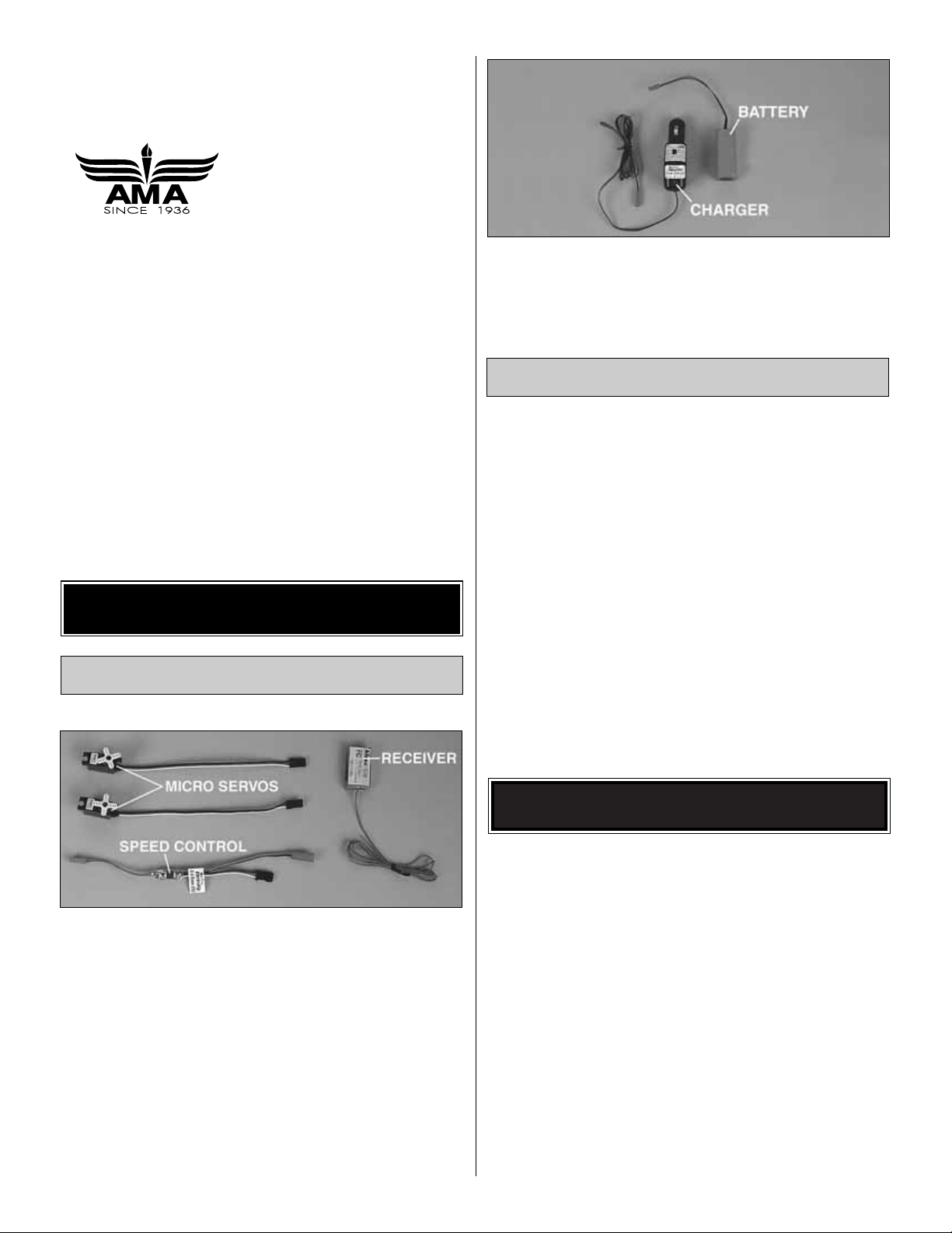
The Spirit of St. Louis ARF requires a three-channel radio
with two micro servos, a mini/micro receiver and a speed
control. Hobbico
®
CS-5
Nano
™
servos (HCAM0090), the
Great Planes
ElectriFly
™
receiver (GPML0040 Hi Band,
GPML0041 Low Band) and the Great Planes C-5
(GPMM2000) or C-10 (GPMM2010) speed control are
recommended.The receiver comes without a crystal, which
must be purchased separately. The order number for the
crystal is FUTL63** (Hi Band) or FUTL62** (Low Band).
Substitute the “**” with the channel number you require. For
example, if the transmitter you plan to fly The Spirit of St.
Louis ARF with is on channel 44, order receiver crystal
FUTL6344. Hi Band receivers are tuned for channels
36 – 60.Low Band receivers are tuned for channels 11 – 35.
Additionally, an 8-cell (9.6 volt) 150 to 350 mAh battery pack
(GPMP0050 – 150 mAh, shown in photo, GPMP0060 – 270
mAh, GPMP0070 – 350 mAh) is required. For charging the
battery, the Great Planes ElectriFly Peak Charger
(GPMM3000) is recommended.
In addition to common household tools, here is the list of
items used to build The Spirit of St. Louis ARF.
❏ 6-minute Epoxy (GPMR6042)
❏ 1/2 oz. Medium CA+ (GPMR6007)
❏ Hobby knife (HCAR0105)
❏ #11 Blades (HCAR0211)
❏ Builder’s triangle (HCAR0480)
❏ Drill and 1/16" drill bit
❏ Double-sided foam tape (GPMQ4440) for mounting
receiver and speed control
❏ Sandpaper and sanding block
❏ Small Phillips screwdriver (#1)
❏ Small T-pins (HCAR5100) or craft pins
·
Since The Spirit of St. Louis ARF is made mostly of foam,
and since CA adhesives commonly used to build R/C model
airplanes dissolve foam, CA should not be used when gluing
foam parts.Therefore, 6-minute epoxy, which is compatible
with foam, is used for most of the construction. Unless
otherwise specified in the instructions, 6-minute epoxy is to
be used for gluing all parts of the model together.There are
a few instances where CA may be used for gluing wood to
wood.You can also use aliphatic resin glue instead of epoxy
if desired.
·
For the strongest bond apply epoxy to bothparts being joined.
IMPORTANT! Two of the most important things you can do
to preserve the radio controlled aircraft hobby are to avoid
flying near full-scale aircraft and avoid flying near or over
groups of people.
IMPORTANT BUILDING NOTES
Building Supplies
Flight Equipment
ADDITIONAL ITEMS REQUIRED
Academy of Model Aeronautics
5151 East Memorial Drive
Muncie, IN 47302
Tele: (800) 435-9262
Fax (765) 741-0057
Or via the Internet at:
http://www.modelaircraft.org
3
Page 4

4
Replacement parts for the Great Planes Spirit of St. Louis ARF are available using the order numbers in the Replacement Parts
List that follows. The fastest, most economical service can be provided by your hobby dealer or mail-order company. Parts may also
be ordered directly from Hobby Services, but full retail prices and shipping and handling charges will apply. Illinois and Nevada residents
will also be charged sales tax.
To locate a hobby dealer, visit the Hobbico web site at
www.hobbico.com
. Choose “Where to Buy” at the bottom of the menu on
the left side of the page.Follow the instructions provided on the page to locate a U .S., Canadian or International dealer.If a hobby shop
is not available, replacement parts may also be ordered from Tower Hobbies at
www.towerhobbies.com
, or by calling toll free
(800) 637-6050, or from Hobby Services by calling (217) 398-0007, or via facsimile at (217) 398-7721. If order ing via fax, include a
Visa
®
or MasterCard®number and expiration date for payment.
Mail parts orders and payments by personal check or money order to:Hobby Services, 3002 N.Apollo Drive, Suite 1, Champaign, IL, 61822
Be certain to specify the order number exactly as listed in the Replacement Parts List. Payment by credit card or personal check
only; no C.O.D.
If additional assistance is required for any reason, contact Product Support by e-mail at
productsupport@g
reatplanes.com
, or by
telephone at (217) 398-8970.
Replacement Parts List
Or
der Number Description How to Purchase
Missing pieces.......................Contact Product Support
Instruction manual.................Contact Product Support
Full-size plans........................Not available
GPMA2710 Wing Set
GPMA2711 Fuselage
GPMA2712 Tail Set
GPMA2713 Cowl
GPMA2714 Landing Gear
GPMG0260 Gear Drive
GPMM1981 Speed Control
GPMG0294 Motor
GPMA2715 Propeller
ORDERING REPLACEMENT PARTS
................
Contact Your Hobby
Supplier to Purchase
These Items
To convert inches to millimeters, multiply inches by 25.4
Page 5
5
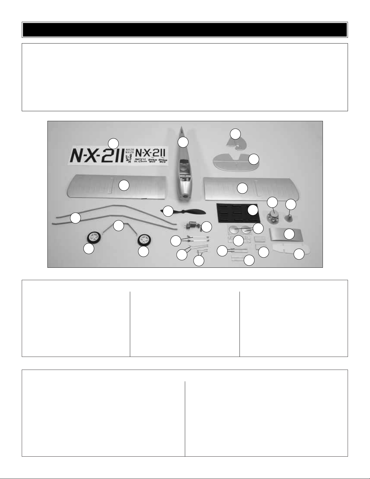
1. Fuselage
2. Vertical Fin
3. Horizontal Stabilizer
4. Decal Sheet
5. Wing Halves (2)
6. Wing Struts (2)
7. Propeller
8. Wheels (2)
9. Main Landing Gear
10. Motor/Gear Box
11. Gear Braces (2)
12. Secondary Str ut Wires (2)
13. Shock Support Wires (2)
14. Cylinders
15. Cowl
16. Spinner
17. Wheel Covers
18. Top Wing Joiner
19. Bottom Wing Joiner
20. Landing Gear Strut Cover (2)
21. Wing Reinforcement Strip (2)
22. Secondary Str ut (2)
23. Tail Str uts (2)
Kit Contents (not photographed)
Kit Contents
(2) Control Horn
(2) Silicone Retainer
(2) Pushrod Connector
(2) Micro FasLinks
(1) 3 x 20mm Wood Screw
(3) 2 x 10mm Wood Screw
(12) 2.4 x 15mm Machine Screw
(2) Axle Screw
(4) 2.4mm Knurled Nuts
(2) Pushrods
(2) Pushrod Guide Tubes
(1) Propeller Adapter
(1) Propeller Spacer
Before starting to build, take an inventory of this kit to make sure it is complete, and inspect the parts to make sure they are of
acceptable quality. If any parts are missing or are not of acceptable quality, or if you need assistance with assembly, contact
Great Planes Product Support. When repor ting defective or missing parts, use the part names exactly as they are written in
the Kit Contents list on this page.
Great Planes Product Support:
Telephone: (217) 398-8970, ext. 5
Fax: (217) 398-7721
E-mail:
airsupport@greatplanes.com
KIT CONTENTS
1
2
4
5
5
7
8
8
3
11
10
13
15
21
22
23
16
17
20
18
19
14
6
9
12
Page 6
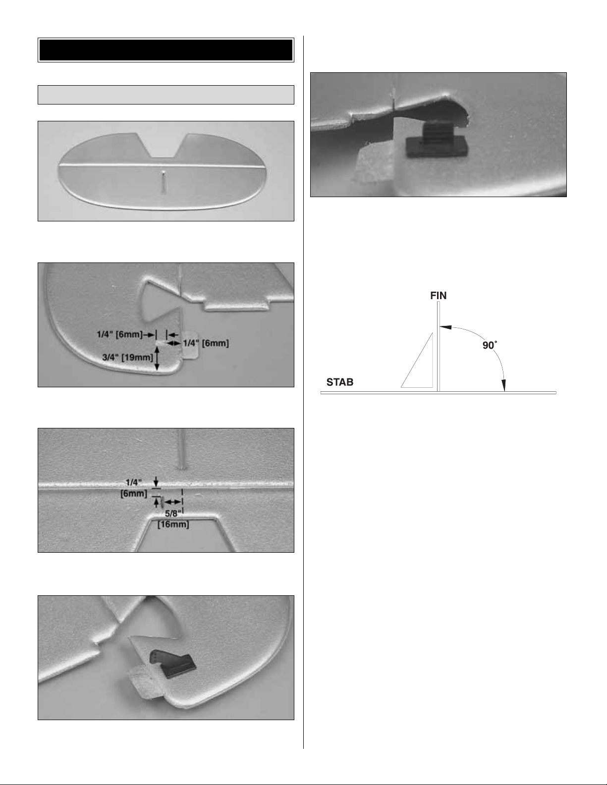
❏ 1. Cut a slot in the stabilizer, using the molded indentation
as a guide.
❏ ❏ 2. Cut a 1/4" [6mm] long slot in the rudder in the
location shown.
❏ ❏ 3. Cut a 1/4" [6mm] long slot in the elevator in the
location shown.
❏ ❏ 4.Glue a control horn into the slot you made in the fin
with a small amount of 6-minute epoxy. When viewed from
the rear, the rudder control horn should be on the left side
of the rudder.
❏ ❏ 5. Glue a plastic control horn retainer onto the back
side of the control horn with 6-minute epoxy.
❏ 6. Repeat this process with the elevator control horn.
When viewed from behind, the control horn should protrude
down from the left side of the elevator joiner.
❏ 7. Use epoxy to glue the fin to the stab. Use a small
builder’ s square to get the fin perpendicular to the stab, then
use tape or small T-pins to hold them together until the
epoxy hardens.
Assemble the Tail Surfaces
ASSEMBLY
6
Page 7

Due to the manufacturing process, there may be some small
surface stress marks on the fuselage and wing.This is normal.
❏ 1.Using the indentations in the aft end of the fuselage as
a guide, cut the slots for the elevator and rudder pushrods.
❏ 2. Use sandpaper to roughen one inch at both ends of
the .094" x 13" [2.4 x 330mm] plastic pushrod guide tubes
with sandpaper.Insert the pushrod guide tubes through the
slots you just cut.Push them forward until they protrude 1/4"
[6mm] beyond the end of the slots.
❏ 3. Insert the front of the pushrod through the two small
holes in the rear former of the battery bay. Secure the
pushrods on both ends with a small drop of epoxy.
❏ 1.Install a wheel onto an axle screw.Tighten one knurled
nut against the shoulder in the axle screw. Make sure the
wheel turns freely on the axle. Do the same with the other
wheel and axle.
Landing Gear Assembly
Assemble the Fuselage
7
Page 8

❏ 2. Assemble the aluminum landing gear, shock support
wire, and one aluminum gear brace onto one of the axles.
Secure the assembly with a knurled nut.Do the same for the
other side.
❏ 3.Drill 1/16" [1.6mm] holes in the bases of the balsa wing
struts, using the punched indentations as a guide. Identify
the front strut. This is the strut with the wider spacing
between holes.
❏ 4.Drill a 1/16" [1.6mm] hole in the front wing strut, 2-1/4"
[57mm] from the bend near the center, as shown.Do this on
both the left and right sides of the strut.
❏ 5. Glue the wire supports into the secondary struts
with CA.
❏ 6.Insert the protruding wires on the secondary struts into
the outer holes in the front strut, and glue them in place.
❏ 7. Screw the rear strut into place on the fuselage, using
the two precut holes at the rear of the hatch.Slip the landing
gear strut cover onto the wires protruding below the front
strut. Do not screw the front strut into place yet.
8
Page 9

❏ 8. Insert the landing gear suppor t wires into the landing
gear strut cover and, using two 2 x 12mm wood screws,
secure the landing gear and front strut into the precut holes
at the front of the hatch.
❏ 9. Secure the landing gear braces with 2 x 10mm
wood screws.
❏ 10.Using 2 x 10mm wood screws, secure the secondary
struts to the fuselage. The front of the strut should be even
with the front of the former.
❏ 11. Cut a 1-1/4" [32mm] long slot along the centerline of
the bottom of the fuselage, starting 1" [25mm] from the
tail end.
❏ 12. Using 6-minute epoxy, glue the tail skid into the slot
you just cut.
❏ 13.T rim the corners of the battery hatch to clear the wing
struts. Use a sharp #11 blade, and remove a little bit of
material at a time until you have a good fit.
❏ 14. Use a very small amount of epoxy to glue the wheel
covers to the wheels.
9
Page 10

❏ 1. Tape the bottom of the two wing panels together with a
single piece of tape.Make sure the leading and trailing edges
are lined up, and the wing panels are tightly butted together.
❏ 2. Flip the wing over, and lightly coat the shaded area
shown with epoxy. Lightly coat the bottom (unpainted side)
of the plastic wing joiner as well.
❏ 3. Prop both wing tips 1-1/2" [38mm] off your work table.
Press the wing joiner down onto the joint of the wing, being
careful to keep it centered. Place a small weight on the
joiner to hold everything tight. Allow the epoxy to harden
before proceeding.
❏ 4. Use 6-minute epoxy to glue the foam wing joiner to the
bottom of the wing. Make sure that it is centered and that the
leading edge of the wing is lined up with the front of the joiner.
❏ 5. Screw the 3 x 20mm wing mounting screw all the way
down into the plastic blind nut in the fuselage.
❏ 6.Test fit the wing to the fuselage by slipping the tongue
at the trailing edge into the fuselage first. Then press the
bottom joiner into the fuselage cutout.It should fit somewhat
tightly. Making sure the wing is properly aligned, press down
on the center of the wing near the leading edge. This will
leave an impression of the wing mounting screw that w e will
use as a guide for drilling.
Wing Construction
10
Page 11

❏ 7. Epoxy the balsa wing reinforcement strips into the
pre-molded indentations in the wings.
❏ 8. Drill a 1/16" [1.6mm] hole through the wing and
reinforcement strips at each of the pre-marked points.
❏ 9. Drill a 7/64" [2.8mm] hole through the wing, using the
impression of the screw that you made earlier as a guide.Make
sure the hole is centered in the screw head impression.
❏ 10.Remove the wing mounting screw from the fuselage and
use it to secure the wing to the fuselage.Do not overtighten.
❏ 11.Thread 2 x 10mm wood screws part-way into the four
holes you drilled in the wing reinforcement strips until they
just begin to protrude out the bottom.
❏ 12. As you perform this step, be very careful not to flex
the wing. Gently lift one of the strut ends up against the
screws that are now protruding from the bottom of the wing.
Secure the strut using the screw.No pilot hole is necessary.
Repeat this with the remaining three struts. Do not
overtighten, as these will easily strip out. You will later be
instructed to harden the “threaded” holes with CA.
❏ 13. Examine both panels of your wing for any twist. If
either wing is twisted, use the procedure outlined below to
straighten them.
11
Page 12

❏ 14. One at a time, unscrew each of the struts from the
wing and use a drop of thin CA to harden the “threads” of
the final hole that you made while adjusting the wing. Allow
the CA to cure, and re-secure the struts.
❏ 1.Hold the fin/stab assembly up to the tail of the fuselage
and mark the top and bottom edges of the rudder hinge.
❏ 2. Cut a slot between the two marks you just made,
following the centerline of the fuselage.
❏ 3. Glue the stab and fin to the fuselage using 6-minute
epoxy. Coat the saddle area on the fuselage with epoxy, as
well as the rudder hinge. As you fit the tail to the fuselage,
be sure to insert the rudder hinge into the slot on the back
of the fuselage. Make sure the fin is centered on the
molded-in seam on the top of the fuselage, and that it is
parallel with the centerline of the fuselage. If necessary,
raise or lower one side of the stab until it is parallel with the
wing. Use pins to hold the stab into position until the epoxy
has fully hardened. Fill any gaps between the stab and fuse
sparingly with additional epoxy.
Attach the Tail
If either of your wing panels has any twist in it, don’t
panic! We can take out this twist by adjusting the struts’
positions on the wing. If the wing panel has wash-in (the
tip of the wing is twisted so that the leading edge is higher
than the trailing edge), then follow these steps:
1. Unscrew the front strut from the wing panel.
2. Reposition the strut so that the screw contacts it a
little closer to the fuselage. Start with about
1/16" [1.6mm].
3. Screw the strut to the wing in this position.This will
pull the leading edge of the wing down and reduce
the wash-in.
4. Check your wing panel for twist.If it still has wash-in,
repeat the procedure. If it has wash-out (the
opposite of wash-in), then go to the wash-out
procedure below. If it’s straight, you’re done!
If the wing panel has wash-out (leading edge lower than
trailing edge), then do the opposite:
1. Unscrew the front strut from the wing panel.
2. Reposition the strut so that the screw contacts it a
little further from the fuselage. Start with about
1/16" [1.6mm].
3. Screw the strut to the wing in this position.This will
push the leading edge of the wing up and reduce
the wash-out.
4. Check your wing panel for twist. If it still has washout, repeat the procedure. If it has wash-in (the
opposite of wash-out), then go to the wash-in
procedure above.If it’s straight, you’re done!
12
Page 13

❏ 4. Using 6-minute epoxy, glue the tail struts onto the
stabilizer and fuselage in the position shown.
❏ 1. Remove the wing by unscrewing the strut screws and
the main wing screw to gain access to the radio
compartment.
❏ 2. Remove the control arms from your servos. Use the
hardware and screws included with your servos to install the
servos upside-down in the servo bay.
❏ 3.Using double-sided tape or hook-and-loop material, install
your receiver and speed control.Install them on opposite sides
of the fuselage to reduce the possibility of interference.
❏ 4.Install the included pushrod connectors onto the servo
arms.You may have to enlarge the holes in your servo arms
to do so. Center the servos with your radio and install the
servo arms onto the servos.
❏ 5. Slip the 1/32" [.8mm] wire pushrods into the pushrod
guide tubes. As they emerge into the radio bay, inser t them
through the pushrod connectors.
❏ 6. Connect the pushrods to the innermost holes on the
control horns. Secure them with the included Micro
FasLinks.Center the control surfaces and tighten down the
easy-adjusters on the servos.
❏ 7. Reinstall the wing.
Radio Installation
13
Page 14

❏ 1. Using three 2 x 10mm wood screws, install the motor
and gearbox onto the firewall. Plug the motor into the
electronic speed control.
❏ 2. Install the prop adapter onto the gearbox output shaft.
❏ 3. Put a mark at the top of the molded plastic cowl. The
center-section of the cowl has a line which points to the top.
Note that this is aligned with the indentation for the top
cylinder. Trim the excess mater ial from the aft edge of the
cowl. Cut a hole in the front of the cowl for the gearbox.
❏ 4.Carefully cut the molded cylinder headsfrom the plastic
sheet. Lightly sand the edges flat and smooth with some
120-grit sandpaper placed flat on your worktable.Glue two of
the cylinder heads together to form a cylinder head assembly.
This is easiest to do if you hold the assembly as shown in the
photo while gluing the center-section together first with CA.
After the CA has cured, hold the assembly in the center and
glue the rippled ends together.
❏ 5. Carefully cut this assembly in half to obtain two
cylinders. Do this for the remaining cylinder heads to obtain
nine complete cylinders.
❏ 6. Glue all nine cylinders to the cowl with medium CA.
❏ 7.Center the cowl on the prop shaft adapter.Drill a 1/16"
[1.6mm] hole through the cowl, into the balsa nose formers
for each screw. Mount the cowl to the fuselage with three
wood screws.This photo shows the finished cowl mounted
to the completed model.
❏ 8. Slip the plastic adapter ring into the propeller. Install
the propeller onto the prop adapter and secure it with the
washer and nut.
Motor Installation
14
Page 15

❏ 9. Cut the excess plastic away from the spinner at the
molded-in cut line. Trim the spinner to fit the propeller. Do
this by removing a small amount of material at a time until
you have a good fit.
❏ 10. Secure the spinner to the prop adapter with the 2 x
15mm machine screw.
IMPORTANT: Whenever connecting the battery always hold
onto the fuselage in case the motor accidentally comes on
and the propeller turns.
❏ 1. Turn on the transmitter and connect the battery to the
speed control in the model. Be certain the r udder, elevator
and motor respond as shown in the chart. If required, use
the reversing function in the transmitter to reverse any
controls necessary so they respond correctly.
❏ 2. Use the ATV function in the transmitter or adjust the
position of the pushrods on the servo arms or the control
horns on the elevator and rudder to get the control surface
throws shown in the chart that follows. The throws are
measured at the widest part of the control surface.
❏ 3. To increase the control surface throw, move the pushrod
to the hole that is closer-in on the control horn on the control
surface, or move the pushrod to the hole that is far ther out
on the servo arm.To decrease the control surface throw, do
the opposite.
Note: Unless you are specifically checking the operation
of the motor, for safety remove the propeller from the
model while setting it up on your workbench.
Set the Control Throws
PREPARE FOR FLYING
15
Page 16

IMPORTANT: The C.G.(center of gravity), or balance point
has the greatest effect on how a model flies .Do not overlook
this important procedure.Modelers who do so often find that
the airplane is difficult to control, or out of control after it is
too late. Preserve your model and insure that the first flight
won’t be the last by balancing the model according to the
following instructions.
The C.G. (center of gravity) must be checked when the
model is ready to fly with the propeller and battery installed.
❏ 1. Use a felt-tip pen or narrow strips of tape to mark the
balance point on the bottom of the wing 1-5/8" [41.3mm]
rearward from the leading edge of the wing on both sides of
the fuselage.
❏ 2. Lift the model right-side up at the balance point you
marked on the bottom of the wing. If the nose drops, the
model is nose-heavy and you must add weight to the tail.If
the tail drops, the model is tail-heavy and you must add
weight to the nose.
❏ 3. If additional weight is required to balance the model,
use small pieces of Great Planes stick-on weight
(GPMQ4485). If weight is required in the nose, do not stick
weight to the cowl.Remove the cowl and stick the weight to
the firewall.If weight is required in the tail, it can be stuck to
the top or bottom of the stab next to the fuselage.
❏ 4. After placing weight on the model where necessary,
recheck the C.G.to confirm that it is correct.
No matter if you fly at an AMA sanctioned R/C club site or if you
fly somewhere on your own, you should always have your
name, address, telephone number and AMA number on or
inside your model.It is required at all AMA R/C club flying sites
and AMA sanctioned flying events .Fill out the identification tag
on page 19 and place it on or inside your model.
Be certain the transmitter batteries are fully charged. Follow
the battery charging instructions that came with your radio
control system to charge the batteries or replace if using
alkaline batteries.
Before you fly y ou should perform one last ov erall inspection
to make sure the model is truly ready to fly and that you
haven’t overlooked anything. If you are not thoroughly
familiar with the operation of R/C models, ask an
experienced modeler to perform the inspection. Check to
see that you have the radio installed correctly and that all
the controls are connected properly .The motor must also be
checked by confirming that the prop is rotating in the correct
direction and the motor sounds like it is reaching full power.
Make certain the elevator and rudder are secure, the
pushrods are connected, the controls respond in the correct
direction, radio components are securely mounted, and the
C.G. is correct.
Ground check the operational range of your r adio bef ore the
first flight of the day. With the transmitter antenna collapsed
and the receiver and transmitter on, you should be able to
walk at least 100 feet away from the model and still have
control. Have an assistant stand by your model and, while
you work the controls, tell you what the control surfaces are
doing. Repeat this test with the motor running at various
speeds with an assistant holding the model, using hand
signals to show you what is happening. If the control
surfaces do not respond correctly, do not fly! Find and
correct the problem first. Look for loose servo connections
or broken wires, corroded wires on old servo connectors,
poor solder joints in your battery pack or a defective cell, or
a damaged receiver crystal from a previous crash.
Range Check
Ground Inspection
Charge the Transmitter Batteries
Identify Y our Model
Balance the Model (C.G.)
Set up the Spirit of St. Louis so it has the following
control surface throws:
ELEVATOR: 5/8"up 5/8"down
[15.9mm] [15.9mm]
RUDDER: 1-1/4" right 1-1/4" left
[31.8mm] [31.8mm]
Second to the C.G., the control throws have the greatest
effect on the way a model flies. Set the throws as close to
these settings as possible. If you have too much control
throw the model may respond too quickly.If you do not have
enough throw you may not be able to maneuver the model
or have enough control to land it when the motor is off.
16
Page 17

• Using multiple batter y packs for successive flights may
cause the motor to become excessively hot, thus causing
damage. Allow the motor to cool for at least 10 minutes
between flights.
• Keep epoxy use to the “useful minimum.” Less weight will
make for better flight perfor mance.
Note: Failure to follow these safety precautions may result
in severe injury to yourself and others.
Get help from an experienced pilot when learning to
operate motors.
Use safety glasses when running motors.
Do not run the motor in an area of loose gravel or sand;the
propeller may throw such material in your face or eyes.
Keep your f ace and body as well as all spectators a wa y from
the path of the propeller as you start and run the motor.
Keep items such as these away from the prop: loose
clothing, shirt sleeves, ties, scarfs, long hair or loose objects
(pencils, screwdrivers) that may fall out of shirt or jacket
pockets into the prop.
The electric motor and motor battery used in The Spirit of
St. Louis ARF are very powerful and the spinning propeller
has a lot of momentum; therefore, if you touch the propeller
while it is spinning it may inflict severe injur y. Respect the
motor and propeller for the damage they are capab le of and
take whatever precautions are necessary to avoid injury.
Always disconnect and remove the motor batter y until you
are ready to fly again and always make sure the transmitter
is turned on before connecting the battery.
Read and abide by the following Academy of Model
Aeronautics Official Safety Code:
GENERAL
1. I will not fly my model aircraft in competition or in the
presence of spectators until it has been proven to be airworthy
by having been previously successfully flight tested.
2. I will not fly my model aircraft higher than approximately
400 feet within 3 miles of an airport without notifying the
airpor t operator. I will give right of way to and avoid flying in
the proximity of full-scale aircraft. Where necessary, an
observer shall be utilized to supervise flying to avoid having
models fly in the proximity of full-scale aircraft.
3.Where established, I will abide by the safety rules for the
flying site I use and I will not willfully and deliberately fly my
models in a careless, reckless and/or dangerous manner.
7. I will not fly my model unless it is identified with my name
and address or AMA number, on or in the model.
RADIO CONTROL
1. I will have completed a successful radio equipment ground
check before the first flight of a new or repaired model.
2. I will not fly my model aircraft in the presence of
spectators until I become a qualified flyer, unless assisted
by an experienced helper.
3.I will perform my initial turn after takeoff away from the pit,
spectator and parking areas and I will not thereafter perform
maneuvers, flights of any sort or landing approaches over a
pit, spectator or parking area.
4. I will operate my model using only radio control frequencies
currently allowed by the F ederal Comm unications Commission.
Though The Spirit of St. Louis ARF is a “Park Flyer,” the best
place to fly any model is at an AMA chartered club field. Club
fields are set up for R/C flying, making your outing safer and
more enjoyable. We recommend that you join the AMA and a
local club so you can have a safe place to fly and have
insurance to cover you in case of a flying accident. The AMA
address and telephone number are in the front of this manual.
If there is no club or R/C flying field in your area, find a suitable
site that is clear of trees, telephone poles, buildings, towers,
busy streets and other obstacles. Since you are not flying at a
sanctioned AMA site, be aware that there may be others like
yourself who could be flying nearby. If both of your models
happen to be on the same frequency, interference will likely
cause one or both of the models to crash. An acceptable
minimum distance between flying models is five miles, so keep
this in mind when searching for a flying site.
In addition to obstacles, it is important to be aware of people
who may wander into the area once you begin flying. At
AMA club flying sites it is a severe rule infraction to fly over
others, and this is a good practice to follow if flying
elsewhere. R/C models tend to attract onlookers whose
numbers can soon multiply, forming small, uncontrolled
crowds. Onlookers pose two main problems. First is the
danger of actually crashing your model into a person,
causing injury .Second is the distraction from those who ask
you questions while you are trying to concentrate on flying.
To minimize or avoid this problem, have an assistant
standing by who can spot people who wander into your
flying site (so you can avoid flying over them) and who can
perform “crowd control” if people star t to gather.
FIND A SAFE PLACE TO FLY
AMA SAFETY CODE (excerpts)
Motor Safety Precautions
Performance Tips
17
Page 18

IMPORTANT: If you are an inexperienced modeler we strongly
urge you to seek the assistance of a competent, experienced
R/C pilot to check your model for airworthiness AND to teach
you how to fly. No matter how stable or “forgiving” The Spirit of
St. Louis ARF is, attempting to learn to fly on your own is
dangerous and may result in destruction of your model or even
injury to yourself and others.Therefore, find an instructor and fly
only under his or her guidance and supervision until you have
acquired the skills necessary for safe and fully controlled
operation of your model.
We recommend flying The Spirit of St.Louis ARF when the wind
is no greater than five miles per hour. Less experienced flyers
should fly only in calm (less than one mile per hour) conditions.
Frequently, winds are calm in the early morning and early
evening.Often these are the most enjoyable times to fly anywa y!
Until you have The Spirit of St. Louis ARF properly trimmed
for level flight, we recommend having an assistant handlaunch the model instead of taking off from the ground.
Turn on the transmitter and plug the battery into the speed
control.Turn the receiver on b y f ollowing the instructions that
came with your speed control.
IMPORTANT: Confirm that the transmitter operates the
controls by moving the sticks and watching the surfaces
respond. Occasionally, electric models have been launched
with the transmitter turned off or the battery disconnected
from the speed control!
When ready to hand launch, the assistant should hold the
bottom of the fuselage behind the main landing gear, then
raise the model high above his head and point it into the
wind.With the pilot
(that would be you!)
standing behind the
plane, fully advance the throttle to start the motor. As soon
as the motor is at full power, the hand launcher should
gently toss the plane into the air at a level or slightly nose-
up attitude.Be certain the model is being launched into the
wind and be immediately ready to make corrections to keep
the airplane flying straight, level and into the wind.
When the model has gained adequate flying speed under its
own power, gently pull the elevator stick back until the
airplane star ts a gradual climb. Many beginners tend to pull
too hard causing the model to stall, so be gentle on the
elevator and don’t panic. If you do pull too hard and you
notice the model losing speed, release the elevator stick
and allow the model to regain airspeed.
Continue a gradual climb and establish a gentle turn until
the airplane reaches an altitude of 75 to 100 feet.
The main purpose of the first few flights is to learn how your
model behaves and to adjust the trims for level flight. After
the model has climbed to a safe altitude reduce the throttle
slightly to slow the model, yet maintain altitude.The Spirit of
St. Louis ARF should fly well and maintain adequate
airspeed at about 1/2 to 3/4 throttle.
Adjust the elevator trim so the model flies le vel at the throttle
setting you are using. Adjust the rudder trim to level the
wings. It may take a few minutes to get the trims adjusted,
but this should be your first priority once at a comfortable
altitude. Continue to fly around, executing turns and making
mental notes (or having your assistant take notes for you) of
what additional adjustments or C.G. changes may be
required to fine tune the model so it flies the way you like.
If The Spirit of St. Louis ARF reaches a high enough altitude,
you may periodically cut off the motor power and glide. This
may extend the flight time by several minutes, especially if you
fly into a rising air current.
Because The Spirit of St. Louis ARF flies slowly, it requires
little room to land. Begin the landing approach by flying
downwind at an altitude of approximately 20 feet [6 meters].
When the airplane is approximately 50 to 100 feet [15 to 30
meters] past you, gradually reduce power and make the
“final” 180° turn into the wind aligning the air plane with the
runway or landing area. Do not dive the airplane, as it will
pick up too much speed. Instead, allow the airplane to
establish a gradual descent. Concentrate on keeping it
heading into the wind toward the runway. When the plane
settles to an altitude of about 4 feet [1 meter], gently apply
a little “up elevator” to level the plane, but be careful as too
much up elevator will cause it to stall.While holding a slight
amount of up elevator, the airplane will slow and descend as
it loses flying speed and touch down on the runway.
Until you are able to accurately judge how far The Spirit of
St. Louis ARF can glide, it may be helpful to reserve some
battery power to run the motor so the plane can be flown
back to the runway.If needed, most BEC systems allow you
to move the throttle to idle and then apply power to get a
short burst of power.
After landing, allow the motor to cool for about 10 minutes
before flying the model again. The battery should also be
allowed to cool for at least 10 minutes before it is recharged.
When speaking of small models, frequently a takeoff from the
ground is called an “ROG”(
rise off ground
) takeoff.Landings on
grass will be a little rough, but doing a ROG takeoff from grass
ROG T akeoff
Landing
Flight
Takeoff
FLYING
18
Page 19

will probably not be possible with The Spir it of St. Louis ARF. If
planning an ROG takeoff, find a smooth, paved surface.
After you have trimmed The Spirit of St. Louis ARF for flight
and have become familiar with its flight characteristics, you
may try some ROG takeoffs.With the model on the runway
and pointing directly into the wind, gently apply power.
Initially, the plane may turn to the left or right because it has
not gained enough speed for the controls to become
effective. Do your best to get through this brief moment and
maintain a straight heading down the runway and into the
wind. Make corrections with the rudder to keep it rolling
straight into the wind. If the model veers too far off, cut the
throttle and try again. As the model begins to gain speed the
controls will become effective.
After the airplane has gained adequate speed (this requires
experience to gauge), gently pull back on the elevator stick
allowing the airplane to become airborne. Release some of
the up elevator control and establish a gentle climb the
same as when you were hand-launching.
Best of luck and happy flying!
Identification T ag
Use this tag or photocopy it and use the copy.Please fill in the
indicated information and place the tag in or on your model.
Great Planes Piper Cub EP Park Flyer ARF
It’s a fresh look at an old f av orite – in a compact, electric version
that's perfect for “grab-and-go” impulse flying. In just 4-6 hours
this Cub is ready for small-field flying, with strong, stick-built
balsa sections and realistic looks enhanced by the trim scheme
and decals. A performance-matched 280 motor, 3.5:1 gearbox
and 10x7 prop are included.Large rudder and elevator surfaces
make for smooth, slow flying with simple, 3-channel radio
control – and an easy-access hatch and band-on wing allow for
convenient on-board gear maintenance and quick battery pack
replacement. GPMA1153
Great Planes Sukhoi SU-31 EP Park Flyer ARF
Now the nearest field for 3D aerobatics ma y be as close as your
own back yard! Built of ultra light materials, the Sukhoi SU-31
ARF can fly at speeds that would make other aircraft stall.Its low
weight also means that servos and control surfaces have less
mass to move and more power a vailable f or speed, strength and
agility. And because it’s an ARF, there’s less “wait” between
buying and flying, too. The Sukhoi SU-31 ARF can be flightready – and floating through its first flight – just a few hours after
you open the box! GPMA1185
Futaba
®
3FR 3-Channel FM Radio
This version of Futaba’s 3FR 3-channel FM radio features
super-light on-board components that are ideal for park
flyers and other weight-sensitive aircraft: the compact
R114F single-conversion receiver and two S3108 micro
servos. Single-stick simplicity makes the 3FR very userfriendly, and the case is ergonomically designed for comfort
and easy access to controls. Performance perks include
V-tail mixing, a proportional 3rd channel, trims, servo
reversing and more. Plus, 600mAh NiCd transmitter
batteries with Sanyo
®
cells and a 50A overnight AC charger
are included. FUTJ53**
OTHER ITEMS AVAILABLE FROM
GREAT PLANES
19
Page 20

BUILDING NOTES
Kit Purchased Date: _______________________
Where Purchased: _________________________
Date Construction Started: __________________
Date Construction Finished: _________________
Finished Weight: __________________________
Date of First Flight: ________________________
FLIGHT LOG
 Loading...