

Page 1
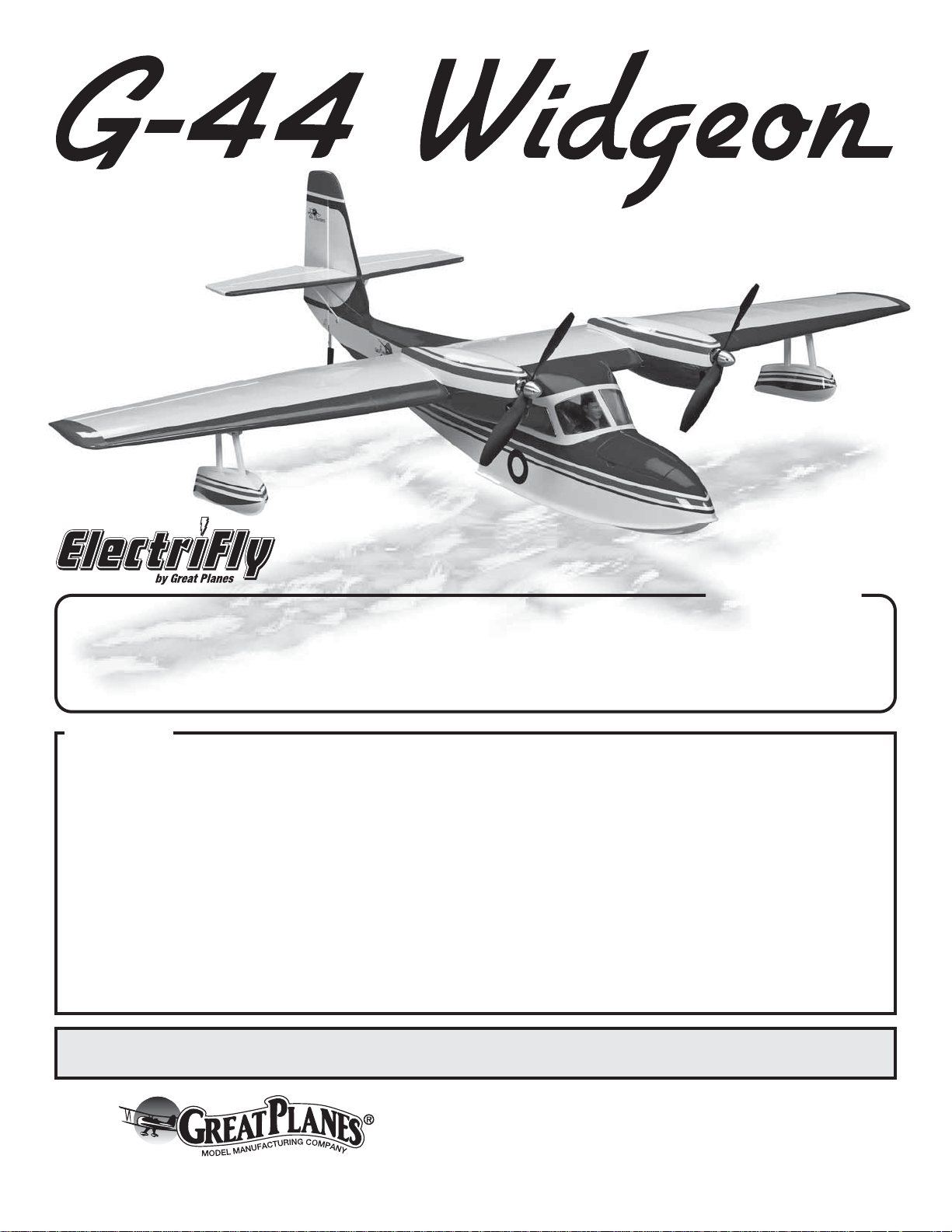
Wingspan: 51 in [1295 mm]
2
Wing Area: 373 in
[24.1 dm2]
Wing Loading: 25−28 oz / ft
Length: 36 in [915mm]
®
2
[76−85 g/dm2]
Weight: 4−4.5 lb
[1810 − 2040 g]
Radio: 4 channel
transmitter & receiver
with four servos
INSTRUCTION
MANUAL
SPECIFICATIONS
Motor: RimFire
two 25 amp ESCs
& two 8×6 props
Battery: 3200 mAh 3S,
11.1 V 20C battery
™
400 (28-30-950),
WARRANTY
Great Planes Model Manufacturing® Co. guarantees this kit to
be free from defects in both material and workmanship at the
date of purchase. This warranty does not cover any component
parts damaged by use or modification. In no case shall Great
Planes’ liability exceed the original cost of the purchased kit.
Further, Great Planes reserves the right to change or modify this
warranty without notice.
In that Great Planes has no control over the final assembly or
material used for final assembly, no liability shall be assumed nor
accepted for any damage resulting from the use by the user of
the final user-assembled product. By the act of using the
user-assembled product, the user accepts all resulting liability.
If the buyer is not prepared to accept the liability associated
with the use of this product, the buyer is advised to return
READ THROUGH THIS MANUAL BEFORE STARTING CONSTRUCTION. IT CONTAINS IMPORTANT
INSTRUCTIONS AND WARNINGS CONCERNING THE ASSEMBLY AND USE OF THIS MODEL.
Entire Contents © 2011 Hobbico,® Inc. All rights reserved.
this kit immediately in new and unused condition to the
place of purchase.
To make a warranty claim send the defective part or item to
Hobby Services at the address below:
Hobby Services
3002 N. Apollo Dr. Suite 1
Champaign IL 61822 USA
Include a letter stating your name, return shipping address, as
much contact information as possible (daytime telephone
number, fax number, e-mail address), a detailed description of
the problem and a photocopy of the purchase receipt. Upon
receipt of the package the problem will be evaluated as quickly
as possible.
Champaign, Illinois
(217) 398-8970, Ext 5
airsupport@greatplanes.com
GPMA1151 v1.1
Page 2

TABLE OF CONTENTS
INTRODUCTION . . . . . . . . . . . . . . . . . . . . . . . . . . . . . . . . 2
Academy of Model Aeronautics . . . . . . . . . . . . . . . . . . 2
SAFETY PRECAUTIONS . . . . . . . . . . . . . . . . . . . . . . . . . 2
DECISIONS YOU MUST MAKE . . . . . . . . . . . . . . . . . . . . 3
Motor Recommendations. . . . . . . . . . . . . . . . . . . . . . . 3
Motor Battery Recommendations . . . . . . . . . . . . . . . . 3
Radio Equipment . . . . . . . . . . . . . . . . . . . . . . . . . . . . . 3
ADDITIONAL ITEMS REQUIRED. . . . . . . . . . . . . . . . . . . 3
Required Hardware and Accessories . . . . . . . . . . . . . 3
Optional Supplies and Tools . . . . . . . . . . . . . . . . . . . . 3
IMPORTANT BUILDING NOTES . . . . . . . . . . . . . . . . . . . 3
KIT INSPECTION . . . . . . . . . . . . . . . . . . . . . . . . . . . . . . . 4
ORDERING REPLACEMENT PARTS . . . . . . . . . . . . . . .4
KIT CONTENTS. . . . . . . . . . . . . . . . . . . . . . . . . . . . . . . . . 5
PREPARATIONS. . . . . . . . . . . . . . . . . . . . . . . . . . . . . . . . 6
Tighten the Covering . . . . . . . . . . . . . . . . . . . . . . . . . . 6
ASSEMBLE THE WINGS . . . . . . . . . . . . . . . . . . . . . . . . . 6
Install the Motors . . . . . . . . . . . . . . . . . . . . . . . . . . . . . 6
Install the Aileron Servos
and Join the Wing Panels . . . . . . . . . . . . . . . . . . . . 7
Install the Motor Nacelles and Sponsons . . . . . . . . . 10
ASSEMBLE THE FUSELAGE . . . . . . . . . . . . . . . . . . . . 11
Install the Stab, Elevators and Rudder . . . . . . . . . . . 11
Install the Servos, Receiver
and Speed Controls in the Fuselage . . . . . . . . . . 15
FINAL ASSEMBLY . . . . . . . . . . . . . . . . . . . . . . . . . . . . . 18
Apply the Decals . . . . . . . . . . . . . . . . . . . . . . . . . . . . 20
GET THE MODEL READY TO FLY. . . . . . . . . . . . . . . . . 20
Battery Precautions . . . . . . . . . . . . . . . . . . . . . . . . . . 20
Check the Control Directions. . . . . . . . . . . . . . . . . . . 20
Set the Control Throws . . . . . . . . . . . . . . . . . . . . . . . 20
Balance the Model (C.G.) . . . . . . . . . . . . . . . . . . . . . 21
Balance the Model Laterally . . . . . . . . . . . . . . . . . . .22
PREFLIGHT. . . . . . . . . . . . . . . . . . . . . . . . . . . . . . . . . . . 22
Identify Your Model . . . . . . . . . . . . . . . . . . . . . . . . . . 22
Charge the Batteries . . . . . . . . . . . . . . . . . . . . . . . . . 22
Balance Propellers. . . . . . . . . . . . . . . . . . . . . . . . . . . 22
Ground Check and Range Check . . . . . . . . . . . . . . . 22
ENGINE SAFETY PRECAUTIONS. . . . . . . . . . . . . . . . . 22
AMA SAFETY CODE EXCERPTS . . . . . . . . . . . . . . . . . 22
General . . . . . . . . . . . . . . . . . . . . . . . . . . . . . . . . . . . 22
Radio Control . . . . . . . . . . . . . . . . . . . . . . . . . . . . . . . 23
CHECK LIST . . . . . . . . . . . . . . . . . . . . . . . . . . . . . . . . . . 23
FLYING. . . . . . . . . . . . . . . . . . . . . . . . . . . . . . . . . . . . . . . 24
Takeoff . . . . . . . . . . . . . . . . . . . . . . . . . . . . . . . . . . . . 24
Flight . . . . . . . . . . . . . . . . . . . . . . . . . . . . . . . . . . . . . 24
Landing . . . . . . . . . . . . . . . . . . . . . . . . . . . . . . . . . . . 24
INTRODUCTION
For the latest technical updates or manual corrections to the
Great Planes G-44 Widgeon EP visit the Great Planes web
site at www.greatplanes.com. Open the “Airplanes” link, then
select the Great Planes G-44 Widgeon EP ARF. If there is
new technical information or changes to this model a “tech
notice” box will appear in the upper left corner of the page.
Academy of Model Aeronautics
If you are not already a member of the AMA, please join! The
AMA is the governing body of model aviation and membership
provides liability insurance coverage, protects modelers’ rights
and interests and is required to fl y at most R/C sites.
Academy of Model Aeronautics
5151 East Memorial Drive
Muncie, IN 47302-9252
Tele. (800) 435-9262
Fax (765) 741-0057
Or via the Internet at: http://www.modelaircraft.org
IMPORTANT!!! Two of the most important things you can
do to preserve the radio controlled aircraft hobby are to avoid
fl ying near full-scale aircraft and avoid fl ying near or over
groups of people.
SAFETY PRE CAUTION S
Protect Your Model, Yourself & Others…
Follow These Important Safety Precautions
1. Your G-44 Widgeon EP should not be considered a toy,
but rather a sophisticated, working model that functions very
much like a full-size airplane. Because of its performance
capabilities, the G-44 Widgeon EP, if not assembled and
operated correctly, could possibly cause injury to yourself or
spectators and damage to property.
2. You must assemble the model according to the instructions.
Do not alter or modify the model, as doing so may result in an
unsafe or unfl yable model. In a few cases the instructions may
differ slightly from the photos. In those instances the written
instructions should be considered as correct.
3. You must take time to build straight, true and strong.
4. You must use an R/C radio system that is in good condition,
a correctly sized engine, and other components as specifi ed
in this instruction manual. All components must be correctly
installed so that the model operates correctly on the ground
and in the air. You must check the operation of the model and
all components before every fl ight.
5. If you are not an experienced pilot or have not fl own this type
of model before, we recommend that you get the assistance
2
Page 3

of an experienced pilot in your R/C club for your fi rst fl ights.
If you’re not a member of a club, your local hobby shop has
information about clubs in your area whose membership
includes experienced pilots.
6. While this kit has been fl ight tested to exceed normal use,
if the plane will be used for extremely high stress fl ying, such
as racing, or if an engine larger than one in the recommended
range is used, the modeler is responsible for taking steps to
reinforce the high stress points and/or substituting hardware
more suitable for the increased stress.
7. WARNING: The fuselage in this kit is made of fi berglass,
the fi bers of which may cause eye, skin and respiratory tract
irritation. Never blow into a part to remove fi berglass dust,
as the dust will blow back into your eyes. Always wear safety
goggles, a particle mask and rubber gloves when grinding,
drilling and sanding fi berglass parts. Vacuum the parts and
the work area thoroughly after working with fi berglass parts.
We, as the kit manufacturer, provide you with a top quality,
thoroughly tested kit and instructions, but ultimately the
quality and fl yability of your fi nished model depends
on how you build it; therefore, we cannot in any way
guarantee the performance of your completed model,
and no representations are expressed or implied as to the
performance or safety of your completed model.
Remembe r: Take your time and follow the instructions
to end up with a well-built model that is straight and true.
torque are required for the ailerons and two servos of at least
39 oz-in (2.8 kg-cm)of torque are required for the elevator and
rudder. We used the following for our test model.
❍ Futaba® R617FS 2.4 receiver (FUTL7627)
❍ Aileron servos. Futaba 3114 (FUTM0414)
❍ Elevator and rudder servos. Futaba 3115 (FUTM0415)
Additionally you will require the following:
❍ Two - 24" [610mm] servo extensions (HCAM2721)
❍ Two - Servo “Y” connecters (FUTM4135)
ADD ITIONAL ITEMS R EQ UI RE D
Required Hardware and Accessories
This is the list of hardware and accessories required to fi nish
the Great Planes G-44 Widgeon EP. Order numbers are
provided in parentheses.
❍ 1/2 oz. [15g] Medium Pro™ CA+ (GPMR6007)
❍ 1/2 oz. [15g] Thin Pro CA (GPMR6001)
❍ Pro 6-minute epoxy (GPMR6045)
❍ #1 Hobby knife (HCAR0105)
❍ Drill Bits -1/16" [1.6mm], 5/64" [2mm]
❍ R/C-56 canopy glue (JOZR5007)
❍ CA applicator tips (HCAR3780)
DECISI ONS YOU MUST MAKE
This is a partial list of items required to fi nish the Great Planes
G-44 Widgeon EP that may require planning or decision
making before starting to build. Order numbers are provided
in parentheses.
Motor Recommendations
The RimFire 400 [28-30-950] (GPMG4560) is the perfect
match for the G-44 Widgeon EP. Two are required along with
two SS-25 ESCs (GPMM1820) and two Great Planes 8×6
Slow-Fly (GPMQ6610) propellers.
Motor Battery Recommendations
We fl ew the G-44 Widgeon EP with the ElectriFly “Power
Series” Lithium Polymer Battery (GPMP0727). The 3200 mAh
3S, 11.1 V 20C battery pack provided great power and fl ight
times consistently more than 5 minutes. The battery proved
to be a good choice to help establish the proper weight and
balance. A Great Planes parallel ESC Adapter (GPMM3141)
is required to connect the two RimFire motors to the battery.
Radio Equipment
The G-44 Widgeon EP requires a four channel radio system
(minimum), four channel receiver (minimum), and four servos.
Two servos with a minimum rating of 21 oz-in (1.5 kg-cm) of
Optional Supplies and Tools
❍ 2 oz. [57g] spray CA activator (GPMR6035)
❍ Mixing sticks (50, GPMR8055)
❍ Mixing cups (GPMR8056)
❍ Masking tape (TOPR8018)
❍ Denatured alcohol (for epoxy clean up)
❍ 21st Century® sealing iron (COVR2700)
Optional Pilot Figure
❍ Williams Brothers 1/8 scale Sportsman Pilot (WBRQ1130)
IMPORTANT BUILDING NOTES
● There are three types of screws used in this kit:
Sheet Metal Screws are designated by a number and a
length. For example #6 × 3/4" [19mm].
This is a number six screw
that is 3/4" [19mm] long.
Machine Screws are designated by a number, threads
per inch, and a length. For example
4-40 × 3/4" [19mm].
This is a number four screw
that is 3/4" [19mm] long with
forty threads per inch.
3
Page 4
Socket Head Cap Screws (SHCS) are designated by
a number, threads per inch, and a length. For example
4-40 × 3/4" [19mm].
This is a 4-40 SHCS that is
3/4" [19mm] long with forty
threads per inch
ORDERING REPLACEMENT PARTS
Replacement parts for the Great Planes G-44 Widgeon EP ARF
are available using the order numbers in the Replacement
Parts List that follows. The fastest, most economical service
can be provided by your hobby dealer or mail-order company.
● When you see the term test fi t in the instructions, it means
that you should fi rst position the part on the assembly
without using any glue, then slightly modify or custom
fi t the part as necessary for the best fi t.
● Whenever the term glue is written you should rely upon
your experience to decide what type of glue to use. When
a specifi c type of adhesive works best for that step, the
instructions will make a recommendation.
● Whenever just epoxy is specifi ed you may use either
30-minute (or 45-minute) epoxy or 6-minute epoxy. When
30-minute epoxy is specifi ed it is highly recommended that
you use only 30-minute (or 45-minute) epoxy, because you
will need the working time and/or the additional strength.
● Photos and sketches are placed before the step they refer
to. Frequently you can study photos in following steps to
get another view of the same parts.
KIT IN SPE CTIO N
Before starting to build, take an inventory of this kit to make
sure it is complete, and inspect the parts to make sure they
are of acceptable quality. If any parts are missing or are not
of acceptable quality, or if you need assistance with assembly,
contact Pr oduct Support. When reporting defective or missing
parts, use the part names exactly as they are written in the
Kit Contents list.
Great Planes Product Support
3002 N Apollo Drive, Suite 1 Ph: (217) 398-8970, ext. 5
Champaign, IL 61822 Fax: (217) 398-7721
E-mail: airsupport@greatplanes.com
To locate a hobby dealer, visit the Great Planes web site at
www.greatplanes.com. Select “Where to Buy” in the menu
across the top of the page and follow the instructions provided
to locate a U.S., Canadian or International dealer.
Parts may also be ordered directly from Hobby Services by
calling (217) 398-0007, or via facsimile at (217) 398-7721, but
full retail prices and shipping and handling charges will apply.
Illinois and Nevada residents will also be charged sales tax. If
ordering via fax, include a Visa® or MasterCard® number and
expiration date for payment.
Mail parts orders Hobby Services
and payments by 3002 N Apollo Drive, Suite 1
personal check to: Champaign IL 61822
Be certain to specify the order number exactly as listed in the
Replacement Parts List. Payment by credit card or personal
check only; no C.O.D.
If additional assistance is required for any reason contact
Product Support by e-mail at productsupport@greatplanes.
com, or by telephone at (217) 398-8970.
REPLACEMENT PARTS LIST
Order No. Description
GPMA4260
GPMA4261
GPMA4262
GPMA4263
GPMA4264
GPMA4265
GPMA4266
GPMA4267
GPMA4268
Fuselage Widgeon EP ARF
Wing Widgeon EP ARF
Tail Set Widgeon EP ARF
Hatch Widgeon EP ARF
Floats Widgeon EP ARF
Nacelles EP Widgeon ARF
Spinner EP Widgeon ARF
Decals Widgeon EP ARF
Water Rudder Widgeon EP ARF
4
Page 5
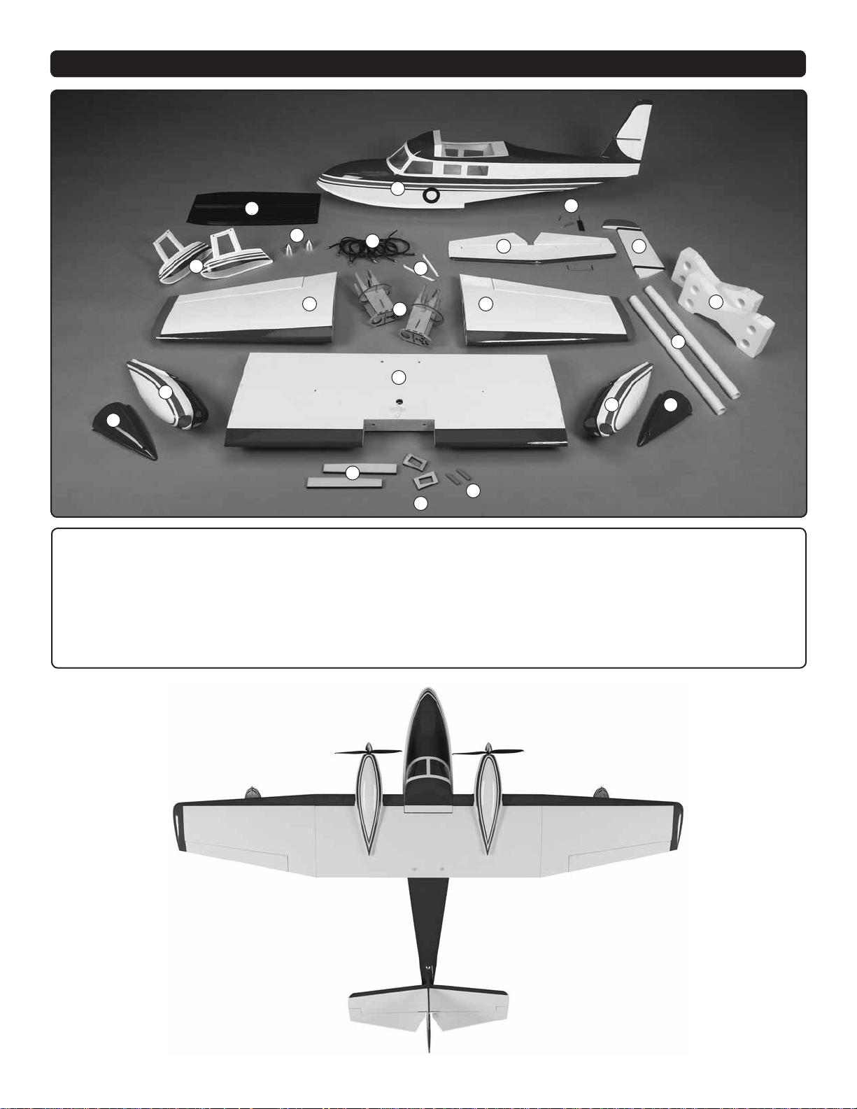
KIT CONTENTS
1
2
7
3
15
16
1. Fuselage
2. Cockpit Floor
3. Sponsons
4. Spinners
5. ESC Extensions
6. Stab and Elevators
7. Water Rudder Assembly
4
9
5
14
10
17
18
20
19
8. Rudder
9. Right Wing and Aileron
10. Motor Mounts
11. Left Wing and Aileron
12. PVC Tubes
13. Fuselage Cradles
14. Horizontal Stabilizer Struts
6
11
8
13
12
15
16
15. Top Nacelles
16. Bottom Nacelles
17. Wing Center Section
18. Wing Joiners
19. Servo Trays
20. Wing Dowels
5
Page 6
PREPARATIONS
Tighten the Covering
Refer to the separate instruction sheet titled How T o Tighten
Covering On ARF Models. Follow the instructions to tighten
the covering. If you prefer to get started on assembly right
away, the tightening process could be done later (but it is
usually easiest to do while the model is still in separate pieces).
ASSEMBLE TH E WINGS
Install the Motors
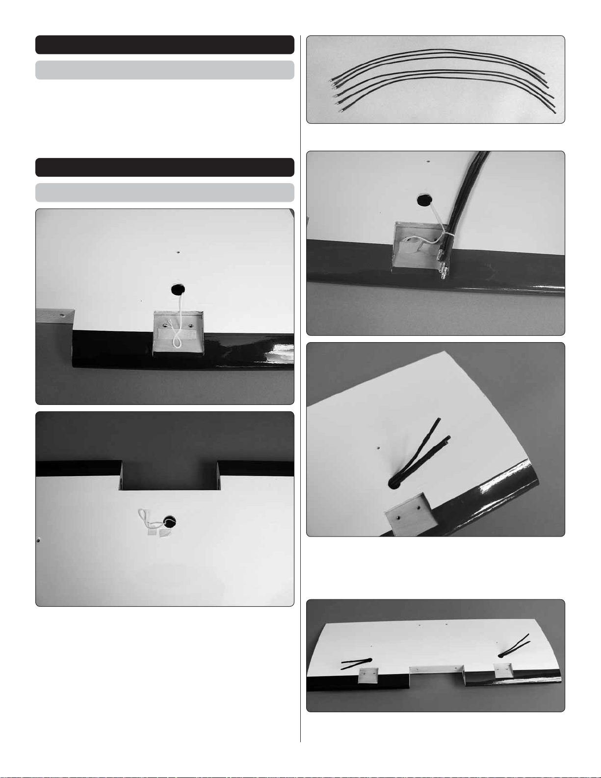
2. Your kit includes six motor extensions.
❏
1. There is a set of strings that are taped to the wing. A
❏
string goes from the hole in the top of the wing by each of the
motor mount locations and exits out the hole in the bottom
center of the wing.
Using the string on the top of the wing located by the motor
mount, tie the male end of three motor leads together and
then pull them through the wing until they exit out the hole in
the bottom center of the wing.
Do this for both of the holes by the motor mount.
6
Page 7
each motor to the motor mounts with three 4-40 x 1/4" [6mm]
screws for each of the motors. Be sure to apply a couple of drops
of thread locker to each of the screws before installing them.
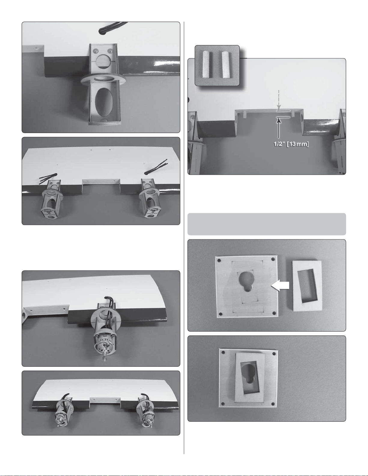
5. Locate the 1/8" x 3/4" [3mm x 19mm] wood dowels. Glue
❏
them into the holes in the leading edge of the wing, making
sure that approximately 1/2" [13mm] of each dowel extends
from the wing.
3. Slide the wood motor mounts in place on the wing.
❏
Secure them to the wing with two 4-40 x 1/2" [13mm] screws
and two #4 washers for each motor mount. Be sure to apply a
couple of drops of thread locker to each of the screws before
installing the screws.
Install the Aileron Servos and
Join the Wing Panels
4. Assemble the motor, prop adapter and motor mount as
❏
instructed in the instructions that came with the motor. Mount
1. Remove the aileron servo cover from the bottom of the
❏ ❏
right wing. Locate one of the plywood servo mounting plates
and position it between the markings on the servo cover. DO
NOT glue them together yet!
7
Page 8
2. Place your servo onto
❏ ❏
the plywood plate, making
sure the servo fi ts through the
hole in the aileron cover. Adjust
the size of the hole in the servo
cover as needed to fi t your
brand of servo. When you are
satisfi ed with the fi t, glue the
plywood plate to the servo
cover.
3. Drill a 1/16" [1.6mm]
❏ ❏
hole through the servo
mounting holes, into the
plywood plate. Do Not drill
through the servo cover.
Mount the servo with two 5/64"
x 1/4" [2mm x 6mm] screws
included in the kit.
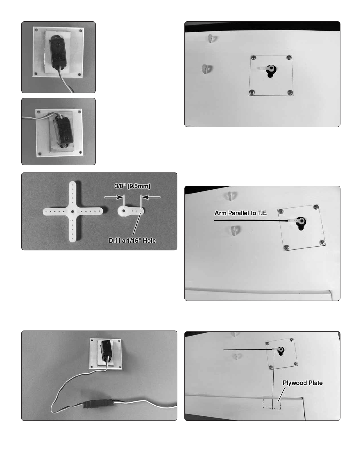
6. Center the servo and then install the servo arm onto
❏ ❏
the servo. Insert and then remove a 5/64 x 3/8" [2mm x 9.5mm]
washer head screw into each of the four mounting holes in
the wing for the servo cover. Apply a couple of drops of thin
CA glue to harden the threads. Once the glue has hardened,
secure the servo cover to the wing with four 5/64 x 3/8" [2mm
x 9.5mm] washer head screws.
4. To continue with the installation you need to have a
❏ ❏
servo arm that is at least 5/32" [4mm] wide. If you are using
the Futaba S3114 servo the standard arm on the servo is
not wide enough but the larger arm included with the servo
is the correct width. Modify the servo arm by cutting off three
arms leaving just one. The servo arm needs to be shortened
so that the distance from the center of the arm to the outer
hole is 3/8" [9.5mm]. Modify the servo arm to match these
specifi cations. Enlarge the outer hole drilling it with a 1/16"
[1.6mm] drill.
5. Install a 24" [610mm] servo extension onto the servo
❏ ❏
lead. Secure the leads with a piece of heat shrink tubing, tape
or some other method to secure the connections.
7. Adjust the servo arm until it is parallel to the aileron.
❏ ❏
You may need to remove the servo and re-install the servo
arm to get the arm aligned with the servo.
8. Look closely at the aileron. Under the covering you
❏ ❏
will see a hardwood plate.
8
Page 9

Hinge Line Hinge Line
Correct Incorrect
FasLink
Servo Horn
Pushrod Wire
10. Use tape to hold the ailerons in the neutral position.
❏ ❏
Make a mark on the pushrods where they cross the outer
holes in the servo arms. Make a 90 degree bend at the mark
on the pushrods and cut off the excess pushrod 1/4" [5mm]
beyond the bend. Attach the pushrods to the servo arms using
nylon Faslinks. Thread the clevis up or down on the pushrod
as necessary to center the aileron. When satisfi ed, slide the
silicone clevis retainer to the end of the clevis to secure it.
11. Locate one of the 1/8" x
❏❏
3/4" [3mm x 19mm] nylon dowels.
Place the aileron control horn on the hardwood plate in line
with the servo arm. Drill a 1/16" [1.6mm] hole through each
of the mounting holes, drilling into the hardwood plate. DO
Not drill through the top of the aileron! Secure the control
horn with two 5/64" x 3/8" [2mm x 9.5mm] screws. Remove
the screws and add a couple of drops of thin CA glue to the
holes to harden the threads. After the glue has dried secure
the horn to the aileron.
Test fi t it into the hole located at the trailing edge of the root
rib. Glue the dowel into the hole leaving 3/8" [9.5mm] of the
pin extending from the root rib.
9. Thread a nylon clevis 20 turns onto a 4-1/4" [110mm]
❏ ❏
pushrod. Slide a silicone clevis retainer onto each clevis and
connect the clevis in the hole, one hole in from the end of the
nylon control horn
12. Attached at the root rib of the wing center section
❏ ❏
is a string that runs out through the wing out the hole on the
bottom center of the wing. Tie the string to the servo lead of
the outer wing panel.
9
Page 10

Install the Motor Nacelles
and Sponsons
13. Locate one of the plywood wing joiners and test fi t
❏ ❏
it into the opening in the wing center section. Slide the outer
wing panel onto the joiner to check the fi t. When you are
satisfi ed with the fi t of the wing panels remove the outer panel
from the center section. Pull the servo lead through the wing
center section and out the hole in the bottom of the wing center
section. Apply epoxy to the joiner, the joiner pocket and the
wing root rib. Tape the wing center section and the outer wing
panel together and allow the glue to harden. Clean excess
glue from the wing with a paper towel and alcohol.
14. Repeat steps 1-13 for the left wing panel.
❏
1. Each nacelle is composed of a top and bottom half.
❏ ❏
Apply a bead of R/C Z 56 to the inside fl ange on the bottom
nacelle. Move quickly to the next step.
2. Place the bottom nacelle on the bottom wing. Align
❏ ❏
the hole in the back of the bottom nacelle with the hole in the
bottom of the wing. Now install the top nacelle (Do Not Glue)
onto the wing, making sure that the nacelle slides over the
fl ange on the bottom nacelle.
10
Page 11

3. Secure the top and bottom nacelle by screwing the
❏ ❏
4-40 x 1-3/4" Phillips head screw into the hole in the bottom
half of the nacelle, through the wing and into the block inside
the top of the nacelle. Tighten the screw until the top and
bottom half of the nacelle fi t snug to the surface of the wing.
Clean away any excess glue from the wing and nacelle. Apply
masking tape to the bottom half of the nacelle to hold it tight
to the wing. Repeat this for the other nacelle. When you have
both nacelles installed set the wing aside to allow it to dry.
4. Install two 1/8" x 3/8" [3mm x 9.5mm] screws into the
❏ ❏
sponson and through the mounting tabs in the wing. Tighten
a 1/8" [3mm] nylon lock nut onto the screws to secure the
sponson.
5. Repeat this to install the other sponson.
❏
ASSEMBLE THE FUSELAGE
Install the Stab, Elevators and Rudder
1. Assemble the foam stand for the fuselage. This will give
❏
a solid platform during the assembly of the fuselage.
11
Page 12

A
A = A' B = B'
A'
B
B'
described below for safely cutting the covering. If you do not
have a hot knife use a sharp hobby knife, carefully cutting the
covering from the stab. Important! Be sure you cut only
through the covering and not into the stab.
How to Cut Covering from Balsa
2. Slide the stab into fuselage. Align the stab as shown in
❏
the sketch.
3. Stand back and look at the stab alignment in relation
❏
to the top of the fuselage. Be sure that the stab is parallel to
the top of the fuselage. If not, lightly sand the stab saddle to
align the stab.
Use a soldering iron to cut the covering from the stab.
The tip of the soldering iron doesn’t have to be sharp, but
a fine tip does work best. Allow the iron to heat fully. Use
a straightedge to guide the soldering iron at a rate that
will just melt the covering and not burn into the wood. The
hotter the soldering iron, the faster it must travel to melt a
fine cut. Peel off the covering.
4. Once you are satisfi ed with the alignment, mark the
❏
shape of the fi n onto the top and bottom of the stab with a
fi ne tip felt tip marker. Remove the stab. Use the technique
5. Install the stab back into the fi n. Double check the
❏
alignment of the stab. When you are satisfi ed with the fi t, wick
some thin CA into the joint to secure the stab to the fi n. Do
this for both the top and the bottom of the stab. Set the model
aside to allow the glue to harden.
12
Page 13

6. On the bottom of the stab and the side of the fuselage
❏
you will fi nd pre-drilled holes for stab supports. Install and then
remove a 5/64" x 1/4" [2mm x 6mm] screw into each of the
four holes. Apply a couple of drops of thin CA into the holes
to harden the threads. After the glue has hardened install the
stab supports with 5/64" x 1/4" [2mm x 6mm] screws.
8. Install a hinge into each of the four hinge slots in the
❏
stab. Test fi t the elevators to the stab. When sliding the elevator
halves onto the hinges be sure that you install the elevator
joiner wire into the hole in the trailing edge of the elevator.
Check to be sure that the two elevator halves are aligned with
each other. If necessary, slightly bend the joiner wire to bring
the elevators into alignment. When you are satisfi ed with the
fi t remove the elevators from the stab.
7. Locate the elevator joiner wire. Slide it through the fi n
❏
at the trailing edge of the stab.
9. Apply a small amount of epoxy into the hole in the elevator
❏
for the elevator joiner wire. Fit the elevator onto the hinges.
Do this for both the left and right elevator.
13
Page 14

10. Apply a couple of drops of thin CA onto the top and
❏
the bottom of the four elevator hinges. Make sure the glue
saturates the hinges and fl ows into the hinge slots.
11. Install the z-bend end of a 3/64" x 20" [1.2mm x 508mm]
❏
pushrod wire into the outer hole of a nylon control horn.
12. Slide the wire into the hole at the back of the fuselage
❏
in the top, right side of the fuselage. Place the control horn on
the elevator as shown. Mark the location of the clevis mounting
holes onto the elevator. Drill a 5/64" [2mm] hole through each
of the marks and through the top of the elevator.
Tighten the screws into the nylon control horn plate on the
top of the elevator.
14. Apply a couple of drops of thin CA to the exposed
❏
balsa trailing edge of the rudder. The application of the glue
is to waterproof the balsa. Allow the glue to harden without
the use of CA accelerator. You do not want any glue build up
in this area.
13. Secure the control horn with 5/64" x 3/8" [2mm x
❏
10mm] screws.
15. Locate the water rudder, water rudder control wire,
❏
aluminum coupler and two 1/8" [3mm] set screws.
16. Apply a small amount of epoxy to the trailing edge of
❏
the rudder and in the hole. Slide the shortest end of the control
wire into the hole. Clean any excess epoxy with a paper towel
wetted with alcohol. Allow the glue to harden.
14
Page 15

17. Apply a couple of drops of thread locker onto one of the
❏
1/8" [3mm] set screws and install it into the aluminum coupler.
Slide the water rudder into the coupler and tighten the set
screw against the fl at spot on the water rudder.
18. Install the remaining set screw into the aluminum coupler.
❏
Slide the coupler onto the water rudder wire. After you are
satisfi ed with the fi t, remove the coupler from the water rudder
wire. For the rest of the assembly process you will fi nd it easier
to handle the model without the water rudder attached to the
rudder. When the model is complete install the water rudder.
Be sure to use thread locker on the set screw.
19. Install three hinges into the trailing edge of the stab and
❏
then test fi t the rudder to the hinges. When you are satisfi ed
that everything fi ts together properly, apply a few drops of thin
CA onto the hinges in the same way you installed the elevators.
20. Install the z-bend end of the remaining 3/64" x 20"
❏
[1.2mm x 508mm] pushrod wire into the outer hole of a nylon
control horn.
21. Slide the wire into the hole at the back of the left side
❏
of the fuselage. Place the control horn on the rudder using
the same technique used on the ailerons. Mark the location of
the clevis mounting holes onto the rudder. Drill a 5/64" [2mm]
hole through each of the marks and through the opposite side
of the rudder.
22. Secure the control horn with 5/64" x 1/2" [2mm x 10mm]
❏
screws and tighten the screws into the nylon control horn plate
on the opposite side of the rudder.
Install the Servos, Receiver and
Speed Controls in the Fuselage
1. Modify the servo arm included with your servo by cutting
❏
off three arms leaving just one. Install a brass screw lock
connector into the outer hole of the servo, securing it with
the plastic retainer. The outer hole of the servo arm should
be approximately 1/2" [13mm] from the center of the servo.
Thread the 2-56 x 1/4" (6mm) socket head caps screw into
the top of the screw lock connector.
15
Page 16

2. Install the elevator servo into the left side of the servo
❏
tray making sure the pushrod wire slides through the screw
lock connector. Drill a 1/16" [1.6mm] hole through the mounting
holes of the servo. Screw the servo in place with the hardware
that came with your servo. Center the servo arm and center
the elevator. Apply a couple of drops of thread locker to the
socket head cap screw. Then, tighten the screw against the
pushrod wire.
speed control be sure to feed the three motor leads and the
signal lead back through the bulk head and into the area of
the servos. Repeat this on the opposite side of the fuselage
for the other speed control.
5. Plug both of the leads from the speed controls into a
❏
“Y” connector. Secure the connections with some heat shrink
tubing, tape or other method to prevent the connections from
becoming unplugged.
3. Install the rudder servo using the same installation
❏
method used for the elevator.
4. From the 8" [203mm] adhesive backed Velcro® cut a
❏
piece approximately 1-1/2" [38mm] long. Apply the softer,
fuzzy side to the speed control and place the opposite side
on the inside of the fuselage as shown. When positioning the
6. Plug the two speed controls into a parallel connector.
❏
7. Cut a 3-1/2" [89mm] length from the #64 rubber band
❏
included with the kit.
16
Page 17

9. From the 8" [203mm] adhesive backed Velcro cut a piece
❏
approximately 3-1/2" [89mm] long. Place the more rigid half
of the Velcro onto the plywood (the fuzzy side of the Velcro
will be applied to the battery). Insert the non-adhesive Velcro
strip through the slots in the plywood plate.
10. Turn the transmitter on and set the throttle stick to idle.
Then, install the battery and plug it into the parallel connector
that the two speed controls are plugged into.
8. Glue one end of the rubber band inside the fuselage
❏
with CA glue. After the glue has hardened glue the rubber
band to the hatch cover. This works as a shock cord and will
prevent you from losing the hatch cover in strong choppy
water. For added security we have included a 1/4" x 2" x 2"
[6mm x 52mm x 52mm] piece of foam. Glue this inside the
cover between the formers with Foam Safe CA glue or fi ve
minute epoxy. This will allow the cover to fl oat if it should ever
become disconnected from the fuselage.
10. Cut another 1-1/2" length of adhesive Velcro. Apply
❏
the softer, fuzzy side to the receiver and place the opposite
side on the plywood plate inside of the fuselage as shown.
Now is a good time to plug all of the servos into the receiver.
Install a Y-connector into the receiver for the ailerons. Place
the wing onto the fuselage and plug the ailerons into the
17
Page 18

receiver. Make sure the controls are all centered and moving
the correct direction. If you have any question about the
direction the surfaces should move refer to the instructions on
page 20 of this manual. When you are satisfi ed that the radio
system is set up properly, place the receiver on the Velcro®.
Next you need to plug in all of the motor leads. Before doing
this remove the nut and washer from the motors. Plug the
right motor into the leads from the right speed control. Plug
the left motor into the remaining leads. Plug the “Y” connector
into the appropriate channel for your receiver. Arm the speed
control. Looking at the front of the motors, check to be sure
that the motors are both turning counter-clockwise. If they do
not turn counter clockwise unplug two of the three leads from
the motor and reverse them. This will change the direction of
the motor rotation. When both motors are turning the correct
direction disconnect the battery.
FINAL ASSEMBLY
2. Install the water rudder onto the water rudder control
❏
wire. Apply a couple of drops of thread locker to the set screw,
align the water rudder with the rudder and tighten the set
screw against the wire.
1. Install the drain plug into the bottom of the fuselage.
❏
Use this plug to drain any water that might get into the fuse
during a fl ight.
3. Apply the self adhesive foam tape to the wing saddle.
❏
This will prevent any water from getting into the fuselage.
4. Locate the two 3/8" x 3/8" x 15/32" [10mm x 10mm x
❏
12mm] wood blocks.
18
Page 19

Glue the blocks where shown in the photo. They should be
located just below the ABS plastic window insert.
6. You may wish to install a pilot. We used a Williams
❏
Brothers 1/8 scale Sportsman Pilot (WBRQ1130). Glue the
pilot on the plastic fl oor on the left side.
5. Locate the black plastic fl oor and insert it into the fuselage.
❏
The front of the fl oor should rest on the wood formers in the
front of the fuselage. The back of the fl oor will rest on the two
blocks you glued to the sides of the fuselage. Drill a 1/16"
[1.6mm] hole through the fl oor and into the blocks. Secure the
fl oor with two 5/64 x 3/8" [2mm x 9.5mm] washer head screws.
7. Mount the wing to the fuselage, securing it with two nylon
❏
wing bolts. Install the props onto the motors. Secure the prop
with the washer that came with the motor and the 3/4" [19mm]
aluminum spinners included with the kit.
19
Page 20

Apply the Decals
FULL
THROTTLE
RUDDER
MOVES
RIGHT
ELEVATOR
MOVES DOWN
RIGHT AILERON
MOVES UP
LEFT AILERON
MOVES DOWN
4-CHANNEL RADIO SETUP
(STANDARD MODE 2)
1. Peel the decals from the sheet.
❏
2. Be certain the model is clean and free from oily fi ngerprints
❏
and dust. Prepare a dishpan or small bucket with a mixture
of liquid dish soap and warm water—about one teaspoon of
soap per gallon of water. Submerse the decal in the soap and
water and peel off the paper backing. Note: Even though the
decals have a “sticky-back” and are not the water transfer type,
submersing them in soap & water allows accurate positioning
and reduces air bubbles underneath.
3. Using the photos on the box, position the decals on the
❏
model where desired. Holding the decal down, use a paper
towel to wipe most of the water away.
4. Use a piece of soft balsa or something similar to squeegee
❏
remaining water from under the decal. Apply the rest of the
decals the same way.
GET TH E MODEL READY TO FLY
Before you can power the radio system and set up the controls,
the motor batteries will need to be charged. Charge the
batteries, and then read the following precautions on how to
connect multiple packs for fl ying the model:
3. Make certain that the control surfaces and the motor
❏
respond in the correct direction as shown in the diagram. If any
of the controls respond in the wrong direction, use the servo
reversing in the transmitter to reverse the servos connected to
those controls. Be certain the control surfaces have remained
centered. Adjust if necessary.
Battery Precautions
We recommend the ElectriFly “Power Series” Lithium
Polymer Battery (GPMP0623). The 3200mAh 3S, 11.1
V 20C battery pack provided great power. IMPORTANT:
Carefully read and follow all the instructions included with
your LiPo battery and battery charger. LiPo batteries are
not forgiving like NiCd or NiMH batteries. Overcharging or
charging the LiPo battery at too high a current will damage
the battery and could damage property.
❏
If necessary, remove the servo arms from the servos and
reposition them so they are centered. Reinstall the screws
that hold on the servo arms.
❏
control surfaces to see if they are centered. If necessary, adjust
the clevises on the pushrods to center the control surfaces.
Check the Control Directions
1. Turn on the transmitter and receiver and center the trims.
2. With the transmitter and receiver still on, check all the
Set the Control Throws
To ensure a successful fi rst fl ight, set up your G-44 Widgeon
EP according to the control throws specifi ed in this manual.
The throws have been determined through actual fl ight
testing and accurate record-keeping, allowing the model to
perform in the manner in which it was intended. If, after you
have become accustomed to the way the G-44 Widgeon
EP fl ies, you would like to change the throws to suit your
taste, that is fi ne. However, too much control throw could
make the model too responsive and diffi cult to control, so
remember, “more is not always better.”
1. Measure the high rate elevator throw fi rst.
❏
2. Hold a ruler vertically on your workbench against the
❏
widest part (front to back) of the trailing edge of the elevator.
Note the measurement on the ruler.
3. Move the elevator up with your transmitter and move the
❏
ruler forward so it will remain contacting the trailing edge. The
distance the elevator moves up from center is the “up” elevator
throw. Measure the down elevator throw the same way.
20
Page 21

The pushrod farther out
means More Throw
The pushrod closer in
means Less Throw
The pushrod farther out
means Less Throw
The pushrod closer in
means More Throw
At the Servos
At the Control Surfaces
4. If necessary, adjust the location of the pushrod on the
❏
servo arm or on the elevator horn, or program the ATVs in
your transmitter to increase or decrease the throw according
to the measurements in the control throws chart.
These are the recommended control surface throws:
Balance the Model (C.G.)
More than any other factor, the C.G. (center of gravity/
balance point) can have the greatest effect on how a model
fl ies and could determine whether or not your fi rst fl ight will
be successful. If you value your model and wish to enjoy it
for many fl ights, DO NOT OVERLOOK THIS IMPORTANT
PROCEDURE. A model that is not properly balanced may
be unstable and possibly unfl yable.
At this stage the model should be in ready-to-fl y condition with
all of the components in place including the complete radio
system, motors, battery, propeller, spinner and pilot.
1. If using a Great Planes C.G. Machine,™ set the rulers to
❏
2" [51mm]. If not using a C.G. Machine, use a fi ne-point felt
tip pen to mark lines on the bottom of the wing on both sides
of the fuselage 2" [51mm] back from the leading edge. Apply
narrow (1/16" [2mm]) strips of tape over the lines so you will
be able to feel them when lifting the model with your fi ngers.
This is where your model should balance for the fi rst
fl ights. Later, you may experiment by shifting the C.G. 1/4"
[6mm] forward or 1/4" [6mm] back to change the fl ying
characteristics. Moving the C.G. forward will improve the
smoothness and stability, but the model will then be less
aerobatic (which may be fi ne for less-experienced pilots).
Moving the C.G. aft makes the model more maneuverable
and aerobatic for experienced pilots. In any case, start at
the recommended balance point and do not at any time
balance the model outside the specifi ed range.
LOW RATE
Up & Down
1/4"
ELEVATORRUDDERAILERONS
[6mm] 6°
Right & Left
5/8"
[16mm] 12°
Up & Down
3/8"
[10mm] 12°
If your radio does not have dual rates, we recommend setting
the throws at the low rate settings.
NOTE: The throws are measured at the widest part of the
elevators, rudder and ailerons.
HIGH RATE
Up & Down
3/8"
[10mm] 8°
Right & Left
1"
[ 25mm] 19°
Up & Down
1/2"
[13mm] 17°
2. With the wing attached to the fuselage, all parts of the
❏
model installed (ready to fl y) and an empty fuel tank, place the
model on a Great Planes CG Machine, or lift it at the balance
point you marked.
3. If the tail drops, the model is “tail heavy.” If possible,
❏
move the battery pack and/or receiver forward to get the
model to balance. If the nose drops, the model is “nose heavy.”
If possible, move the battery pack and/or receiver aft. If the
receiver and/or battery cannot be moved, or if additional weight
is still required, nose weight may be easily added by using
Great Planes “stick-on” lead (GPMQ4485) and installing it as
far forward in the nose of the fuselage as possible. To fi nd out
how much weight is required, place incrementally increasing
amounts of weight on the top of the fuselage over the location
where it would be mounted inside until the model balances.
21
Page 22

Once you have determined the amount of weight required, it
can be permanently attached. If you need tail weight the best
place to apply it would be to the bottom of the horizontal stab.
4. IMPORTANT: If you found it necessary to add any weight,
❏
recheck the C.G. after the weight has been installed.
Balance the Model Laterally
1. With the wing level, have an assistant help you lift the
❏
model at the center of the bottom of the fuselage and the
bottom of the fuse under the fi n. Do this several times.
2. If one wing always drops when you lift the model, it means
❏
that side is heavy. Balance the airplane by adding weight to the
other wing tip. An airplane that has been laterally balanced
will track better in loops and other maneuvers.
PREFLIGHT
Identify Your Model
No matter if you fl y at an AMA sanctioned R/C club site or if
you fl y somewhere on your own, you should always have your
name, address, telephone number and AMA number on or
inside your model. It is required at all AMA R/C club fl ying sites
and AMA sanctioned fl ying events. Fill out the identifi cation
tag on page 24 and place it on or inside your model.
Charge the Batteries
will engine mounting screws and bolts loosen, possibly with
disastrous effect, but vibration may also damage your radio
receiver and battery. Vibration can also cause your fuel to
foam, which will, in turn, cause your engine to run hot or quit.
We use a Top Flite® Precision Magnetic Prop Balancer
(TOPQ5700) in the workshop and keep a Great Planes
Fingertip Prop Balancer (GPMQ5000) in our fl ight box.
Ground Check and Range Check
Run the motors at full power for a couple of minutes. Afterward,
shut the motors off and inspect the model closely, making
sure all fasteners, pushrods and connections have remained
tight and the hinges are secure. Always ground check the
operational range of your radio before the fi rst fl ight of the
day following the manufacturer’s instructions that came with
your radio. This should be done once with the engine off and
once with the engine running at various speeds. If the control
surfaces do not respond correctly, do not fl y! Find and correct
the problem fi rst. Look for loose servo connections or broken
wires, corroded wires on old servo connectors, poor solder
joints in your battery pack or a defective cell, or a damaged
receiver crystal from a previous crash.
ENGINE SAFETY PRECAUTION S
Failure to follow these safety precaut ions m ay re sult
in severe injury to yourself and others.
Follow the battery charging instructions that came with your
battery to charge the batteries.
IMPORTANT: Carefully read and follow all the instructions
included with your LiPo battery and battery charger. LiPo
batteries are not forgiving like NiCd or NiMH batteries.
Overcharging or charging the LiPo battery at too high a
current will damage the battery and could damage property.
Charge your transmitter following the instruction with the
transmitter.
Balance Propellers
● Get help from an experienced pilot when learning to operate
motors.
● Use safety glasses when starting or running engines.
● Do not run the motor in an area of loose gravel or sand;
the propeller may throw such material in your face or eyes.
● Keep your face and body as well as all spe c tator s away from
the plane of rotation of the propeller as you run the motor.
● Keep these items away from the prop: loose clothing, shirt
sleeves, ties, scarfs, long hair or loose objects such as
pencils or screwdrivers that may fall out of shirt or jacket
pockets into the prop.
AMA SAFETY CODE EXCERPTS
Read and abide by the following excerpts from the Academy
of Model Aeronautics Safety Code. For the complete Safety
Code refer to Model A viation magazine, the AMA web site or
the Code that came with your AMA license.
General
Carefully balance your propellers and spare propellers before
you fl y. An unbalanced prop can be the single most signifi cant
cause of vibration that can damage your model. Not only
1) I will not fl y my model aircraft in sanctioned events, air shows,
or model fl ying demonstrations until it has been proven to be
airworthy by having been previously, successfully fl ight tested.
22
Page 23

2) I will not fl y my model aircraft higher than approximately
400 feet within 3 miles of an airport without notifying the
airport operator. I will give right-of-way and avoid fl ying in the
proximity of full-scale aircraft. Where necessary, an observer
shall be utilized to supervise fl ying to avoid having models fl y
in the proximity of full-scale aircraft.
3) Where established, I will abide by the safety rules for the
fl ying site I use, and I will not willfully and deliberately fl y my
models in a careless, reckless and/or dangerous manner.
2. Be certain the battery and receiver are securely mounted
❏
in the fuse. Simply stuffi ng them into place with foam rubber
is not suffi cient.
3. Extend your receiver antenna and make sure it has a
❏
strain relief inside the fuselage to keep tension off the solder
joint inside the receiver.
4. Balance your model laterally as explained in the
❏
instructions.
5) I will not fl y my model unless it is identifi ed with my name
and address or AMA number, on or in the model. Note: This
does not apply to models while being fl own indoors.
7) I will not operate models with pyrotechnics (any device that
explodes, burns, or propels a projectile of any kind).
Radio Control
1) I will have completed a successful radio equipment ground
check before the fi rst fl ight of a new or repaired model.
2) I will not fl y my model aircraft in the presence of spectators
until I become a qualified flier, unless assisted by an
experienced helper.
3) At all fl ying sites a straight or curved line(s) must be
established in front of which all fl ying takes place with the
other side for spectators. Only personnel involved with fl ying
the aircraft are allowed at or in the front of the fl ight line.
Intentional fl ying behind the fl ight line is prohibited.
4) I will operate my model using only radio control frequencies
currently allowed by the Federal Communications Commission.
5) I will not kno wingly operate my model within three miles
of any pre-existing fl ying site except in accordance with
the frequency sharing agreement listed [in the complete
AMA Safety Code].
9) Under no circumstances may a pilot or other person touch
a powered model in fl ight; nor should any part of the model
other than the landing gear, intentionally touch the gr ound,
except while landing.
5. Use threadlocking compound to secure critical fasteners
❏
such as the set screws that hold the wheel axles to the struts,
screws that hold the carburetor arm (if applicable), screw-lock
pushrod connectors, etc.
6. Make sure all hinges are securely glued in place.
❏
7. Reinforce holes for wood screws with thin CA where
❏
appropriate (servo mounting screws, cowl mounting screws,
etc.).
8. Confi rm that all controls operate in the correct direction
❏
and the throws are set up according to the manual.
9. Make sure there are silicone retainers on all the clevises
❏
and that all servo arms are secured to the servos with the
screws included with your radio.
10. Secure connections between servo wires and
❏
Y-connectors or servo extensions, and the connection between
your battery pack and the on/off switch with vinyl tape, heat
shrink tubing or special clips suitable for that purpose.
11. Make sure any servo extension cords you may have used
❏
do not interfere with other systems (servo arms, pushrods, etc.).
12. Balance your propeller (and spare propellers).
❏
13. Tighten the propeller nut and spinner.
❏
14. Place your name, address, AMA number and telephone
❏
number on or inside your model.
15. If you wish to photograph your model, do so before
❏
your fi rst fl ight.
CHECK LIST
During the last few moments of preparation your mind
may be elsewhere anticipating the excitement of the fi rst
fl ight. Because of this, you may be more likely to overlook
certain checks and procedures that should be performed
before the model is fl own. To help avoid this, a check list
is provided to make sure these important areas are not
overlooked. Many are covered in the instruction manual,
so where appropriate, refer to the manual for complete
instructions. Be sure to check the items off as they are
completed (that’s why it’s called a check list!).
1. Check the C.G. according to the measurements provided
❏
in the manual.
16. Range check your radio when you get to the fl ying fi eld.
❏
23
Page 24

FLYING
The Great Planes G-44 Widgeon EP is a great-fl ying model
that fl ies smoothly and predictably. The G-44 Widgeon EP does
not, however, possess the self-recovery characteristics of a
primary R/C trainer and should be fl own only by experienced
R/C pilots.
CAUTION (THIS APPLIES TO ALL R/C AIRPLANES): If,
while fl ying, you notice an alarming or unusual sound such
as a low-pitched “buzz,” this may indicate control surface
fl utter. Flutter occurs when a control surface (such as an
aileron or elevator) or a fl ying surface (such as a wing or
stab) rapidly vibrates up and down (thus causing the noise).
In extreme cases, if not detected immediately, fl utter can
actually cause the control surface to detach or the fl ying
surface to fail, thus causing loss of control followed by
an impending crash. The best thing to do when fl utter is
detected is to slow the model immediately by reducing
power, then la nd as so on as safely possib le. Id entif y which
surface fl uttered (so the problem may be resolved) by
checking all the servo grommets for deterioration or signs of
vibration. Make certain all pushrod linkages are secure and
free of play. If it fl uttered once, under similar circumstances
it will probably fl utter again unless the problem is fi xed.
Some things which can cause fl utter are; Excessive hinge
gap; Not mounting control horns solidly; Poor fi t of clevis
pin in horn; Side-play of wire pushrods caused by large
be nds; Exce ssive free play in ser vo gears ; Inse c ure ser vo
mounting; and one of the most prevalent causes of fl utter;
Flying an over-powered model at excessive speeds.
Takeoff
Before you get ready to takeoff, see how the model handles
in the water. Hold “up” elevator to keep the water rudder in the
water. It is important that you take off directly into the wind and
that you keep the wings level so that you do not accidentally
catch a sponson in the water. When you’re ready, point the
model directly into the wind, hold a bit of up elevator to keep
the tail in the water then gradually advance the throttle. As
the model gains speed decrease up elevator, allowing the
tail to come off the water. Be ready to apply right rudder to
counteract engine torque. Gain as much speed as is practical
before gently applying up elevator, lifting the model into the
air. Be smooth on the elevator stick, allowing the model to
establish a gentle climb to a safe altitude before turning into
the traffi c pattern.
Flight
For reassurance and to keep an eye on other traffi c, it is a
good idea to have an assistant with you. Tell him to remind you
to throttle back once the plane gets to a comfortable altitude.
While full throttle is usually desirable for takeoff, most models
fl y more smoothly at reduced speeds.
Take it easy with the Widgeon for the fi rst few fl ights, gradually
getting acquainted with it as you gain confi dence. Adjust the
trims to maintain straight and level fl ight. After fl ying around
for a while, and while still at a safe altitude with plenty of fuel,
practice slow fl ight and execute practice landing approaches
by reducing the throttle to see how the model handles at slower
speeds. Add power to see how she climbs as well. Continue
to fl y around, executing various maneuvers. Though not scale
maneuvers, the Widgeon is capable of loops, rolls, inverted
fl ight, etc. Pay attention to your batteries and be sure that you
have enough power to land and taxi back to the shoreline.
Landing
To initiate a landing approach, lower the throttle while on the
downwind leg. Allow the nose of the model to pitch downward
to gradually bleed off altitude. Continue to lose altitude, but
maintain airspeed by keeping the nose down as you turn onto
the crosswind leg. Make your fi nal turn into the wind keeping
the nose down to maintain airspeed and control. Level the
attitude when the model is a couple of feet off of the water,
modulating the throttle as necessary to maintain your glide path
and airspeed. If you are going to overshoot, smoothly advance
the throttle (always ready on the right rudder to counteract
torque) and climb out to make another attempt. When you’re
ready to make your landing, fl are when the model is a foot
or so off the water and smoothly increase up elevator until it
gently touches down. Once the model is in the water, hold up
elevator and taxi back to shore. Remember to think.
Have a ball! But always stay in control
and fl y in a safe manner.
GOOD LUCK AND GREAT FLYING!
Name
Address
City, State, Zip
This model belongs to:
AMA Number
Phone Number
24
 Loading...