

Page 1
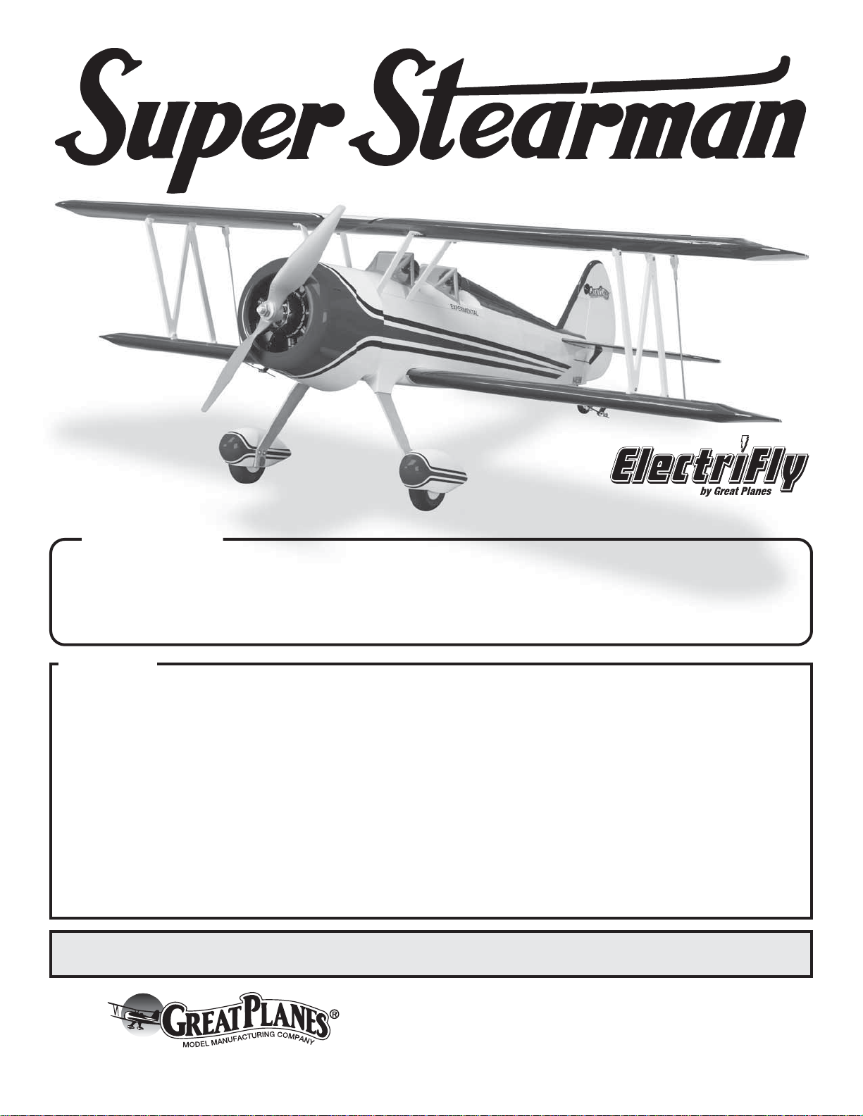
SPECIFICATIONS
Wingspan: 36 in [915 mm]
2
Wing Area: 365 in
[23.5 dm2]
Wing Loading: 14−17 oz/ ft
Length: 29.5 in [750 mm]
2
[43−52 g/dm2]
Weight: 2.25 − 2.75 lb
Radio: Minimum 4-channel
WARRANTY
Great Planes Model Manufacturing® Co. guarantees this kit to
be free from defects in both material and workmanship at the
date of purchase. This warranty does not cover any component
parts damaged by use or modification. In no case shall Great
Planes’ liability exceed the original cost of the purchased kit.
Further, Great Planes reserves the right to change or modify this
warranty without notice.
In that Great Planes has no control over the final assembly or
material used for final assembly, no liability shall be assumed nor
accepted for any damage resulting from the use by the user of
the final user-assembled product. By the act of using the
user-assembled product, the user accepts all resulting liability.
If the buyer is not prepared to accept the liability associated
with the use of this product, the buyer is advised to return
INSTRUCTION MANUAL
™
.10 [35 − 30 − 1250],
[1020 −1250 g]
Power
System:
Rimfire
SS35, 2200 mAh 3S LiPo,
APC 10×7E, 35A ESC
with 4 micro servos
this kit immediately in new and unused condition to the
place of purchase.
To make a warranty claim send the defective part or item to
Hobby Services at the address below:
Hobby Services
3002 N. Apollo Dr. Suite 1
Champaign IL 61822 USA
Include a letter stating your name, return shipping address, as
much contact information as possible (daytime telephone
number, fax number, e-mail address), a detailed description of
the problem and a photocopy of the purchase receipt. Upon
receipt of the package the problem will be evaluated as quickly
as possible.
®
READ THROUGH THIS MANUAL BEFORE STARTING CONSTRUCTION. IT CONTAINS IMPORTANT
INSTRUCTIONS AND WARNINGS CONCERNING THE ASSEMBLY AND USE OF THIS MODEL.
Entire Contents © 2011 Hobbico,® Inc. All rights reserved.
Champaign, Illinois
(217) 398-8970, Ext 5
airsupport@greatplanes.com
GPMA1150 Mnl
Page 2
TABLE OF CONTENTS
INTRODUCTION . . . . . . . . . . . . . . . . . . . . . . . . . . . . . . . . 2
Academy of Model Aeronautics . . . . . . . . . . . . . . . . . . 2
SAFETY PRECAUTIONS . . . . . . . . . . . . . . . . . . . . . . . . . 2
DECISIONS YOU MUST MAKE . . . . . . . . . . . . . . . . . . . . 3
Motor / Battery Recommendations . . . . . . . . . . . . . . . 3
Radio Equipment . . . . . . . . . . . . . . . . . . . . . . . . . . . . . 3
ADDITIONAL ITEMS REQUIRED. . . . . . . . . . . . . . . . . . . 3
Required Hardware and Accessories . . . . . . . . . . . . . 3
Adhesive & Building Supplies . . . . . . . . . . . . . . . . . . . 3
Optional Supplies and Tools . . . . . . . . . . . . . . . . . . . . 3
IMPORTANT BUILDING NOTES . . . . . . . . . . . . . . . . . . . 3
KIT INSPECTION . . . . . . . . . . . . . . . . . . . . . . . . . . . . . . . 4
ORDERING REPLACEMENT PARTS . . . . . . . . . . . . . . . 4
KIT CONTENTS. . . . . . . . . . . . . . . . . . . . . . . . . . . . . . . . . 5
PREPARATIONS. . . . . . . . . . . . . . . . . . . . . . . . . . . . . . . . 6
Tighten the Covering . . . . . . . . . . . . . . . . . . . . . . . . . . 6
ASSEMBLE THE WINGS . . . . . . . . . . . . . . . . . . . . . . . . . 6
Install the Aileron Servos and Pushrods . . . . . . . . . . . 6
Install the Stab, Elevators, Fin and Rudder . . . . . . . . . 8
Install the Landing Gear, Wheels,
Wheel Pants and Turtledeck . . . . . . . . . . . . . . . . . 12
Install the Motor Speed Control,
Receiver and Servos . . . . . . . . . . . . . . . . . . . . . . . 14
Install the Cabanes, Wings and Struts. . . . . . . . . . . . 16
Final Assembly. . . . . . . . . . . . . . . . . . . . . . . . . . . . . . 18
Apply the decals . . . . . . . . . . . . . . . . . . . . . . . . . . . . 18
GET THE MODEL READY TO FLY. . . . . . . . . . . . . . . . . 19
Install & Connect the Motor Battery. . . . . . . . . . . . . . 19
Check the Control Directions. . . . . . . . . . . . . . . . . . . 19
Set the Control Throws . . . . . . . . . . . . . . . . . . . . . . . 19
Balance the Model (C.G.) . . . . . . . . . . . . . . . . . . . . . 20
Balance the Model Laterally . . . . . . . . . . . . . . . . . . . 20
PREFLIGHT. . . . . . . . . . . . . . . . . . . . . . . . . . . . . . . . . . . 20
Identify Your Model . . . . . . . . . . . . . . . . . . . . . . . . . . 20
Charge the Batteries . . . . . . . . . . . . . . . . . . . . . . . . . 20
Balance Propellers. . . . . . . . . . . . . . . . . . . . . . . . . . . 21
Ground Check & Range Check . . . . . . . . . . . . . . . . . 21
MOTOR SAFETY PRECAUTIONS . . . . . . . . . . . . . . . . . 21
AMA SAFETY CODE . . . . . . . . . . . . . . . . . . . . . . . . . . . 21
General . . . . . . . . . . . . . . . . . . . . . . . . . . . . . . . . . . . 21
Radio Control . . . . . . . . . . . . . . . . . . . . . . . . . . . . . . . 21
CHECK LIST . . . . . . . . . . . . . . . . . . . . . . . . . . . . . . . . . . 22
FLYING. . . . . . . . . . . . . . . . . . . . . . . . . . . . . . . . . . . . . . . 22
Takeoff . . . . . . . . . . . . . . . . . . . . . . . . . . . . . . . . . . . . 22
Flight . . . . . . . . . . . . . . . . . . . . . . . . . . . . . . . . . . . . . 23
Landing . . . . . . . . . . . . . . . . . . . . . . . . . . . . . . . . . . . 23
INTRODUCTION
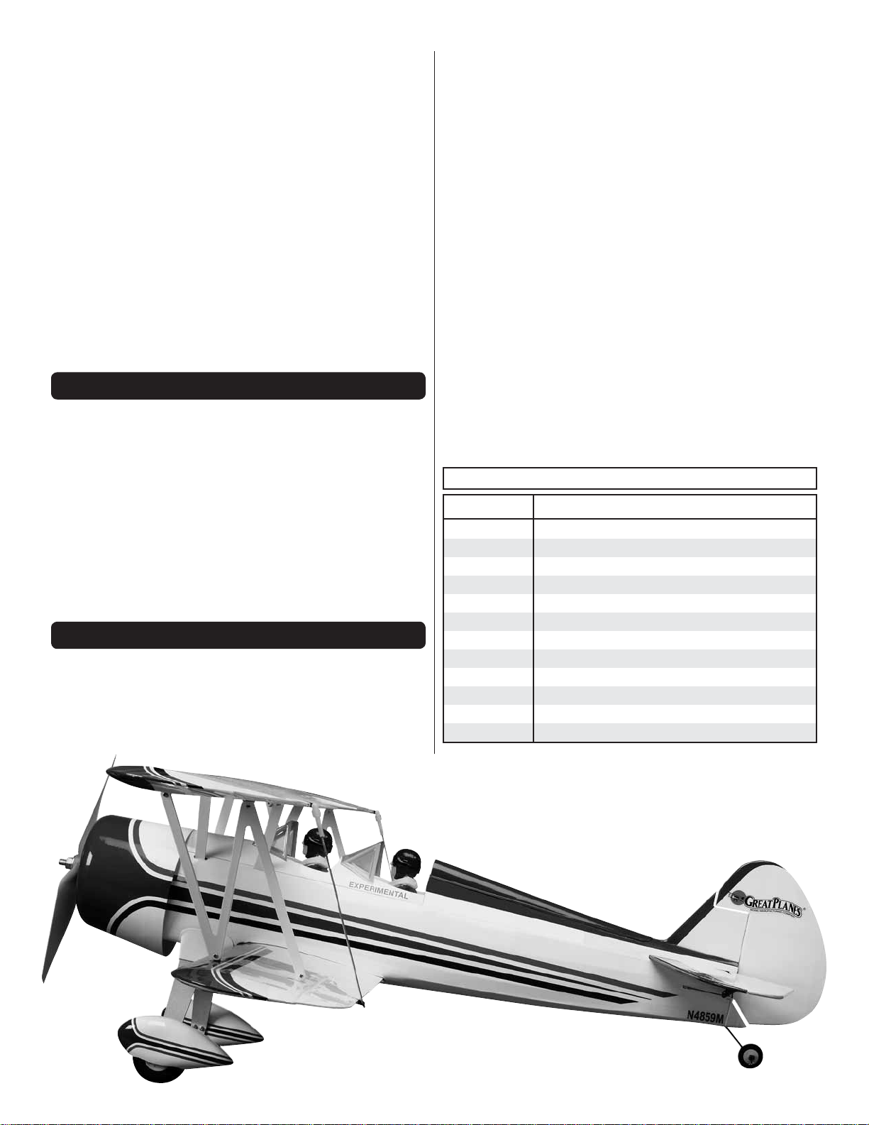
For the latest technical updates or manual corrections to the
Great Planes Super Stearman EP visit the Great Planes web
site at www.greatplanes.com. Open the “Airplanes” link, then
select the Great Planes Super Stearman EP ARF. If there is
new technical information or changes to this model a “tech
notice” box will appear in the upper left corner of the page.
Academy of Model Aeronautics
If you are not already a member of the AMA, please join! The
AMA is the governing body of model aviation and membership
provides liability insurance coverage, protects modelers’ rights
and interests and is required to fl y at most R/C sites.
Academy of Model Aeronautics
5151 East Memorial Drive
Muncie, IN 47302-9252
Tele. (800) 435-9262
Fax (765) 741-0057
Or via the Internet at: http://www.modelaircraft.org
IMPORTANT!!! Two of the most important things you can
do to preserve the radio controlled aircraft hobby are to avoid
fl ying near full-scale aircraft and avoid fl ying near or over
groups of people.
SAFETY PRE CAUTION S
Protect Your Model, Yourself & Others…
Follow These Important Safety Precautions
1. Your Super Stearman EP should not be considered a toy,
but rather a sophisticated, working model that functions very
much like a full-size airplane. Because of its performance
capabilities, the Super Stearman EP, if not assembled and
operated correctly, could possibly cause injur y to yourself or
spectators and damage to property.
2. You must assemble the model according to the
instructions. Do not alter or modify the model, as doing
so may result in an unsafe or unfl yable model. In a few cases
the instructions may differ slightly from the photos. In those
instances the written instructions should be considered
as correct.
3. You must take time to build straight, true and strong.
4. You must use an R/ C radio system that is i n good co n dition,
a correctly sized motor, and other components as specifi ed
in this instruction manual. All components must be correctly
installed so that the model operates correctly on the ground
and in the air. You must check the operation of the model
and all components before every fl i g h t .
2
Page 3
5. If you are not an experienced pilot or have not fl own this type
of model before, we recommend that you get the assistance
of an experienced pilot in your R/C club for your fi rst fl ights.
If you’re not a member of a club, your local hobby shop has
information about clubs in your area whose membership
includes experienced pilots.
6. While this kit has been fl ight tested to exceed normal use,
if the plane will be used for extremely high stress fl ying, such
as racing, or if a motor larger than one in the recommended
range is used, the modeler is responsible for taking steps to
reinforce the high stress points and/or substituting hardware
more suitable for the increased stress.
Futaba® S3114 servos (FUTM0414). In addition you will need:
❍ 3 - 6" [150mm] servo extension (HCAM2701 for Futaba)
❍ 1 - 6" Y-harness (FUTM4135)
ADD ITIONAL ITEMS R EQ UI RE D
Required Hardware & Accessories
This is the list of hardware and ac cessories required to fi nish
the Great Planes Super Stearman EP. Order numbers are
provided in parentheses.
7. Carefully read and follow all the instructions included with
your LiPo battery and battery charger. LiPo batteries are
not forgiving like NiCd or NiMH batteries. Overcharging or
charging the LiPo battery at too high a current will damage
the battery and could damage property.
8. WARNING: The cowl and wheel pants included in this kit
are made of fi berglass, the fi bers of which may cause eye,
skin and respiratory tract irritation. Never blow into a part
(wheel pant, cowl) to remove fi berglass dust, as the dust
will blow back into your eyes. Always wear safety goggles, a
particle mask and rubber gloves when grinding, drilling and
sanding fi berglass parts. Vacuum the parts and the work area
thoroughly after working with fi berglass parts.
We, as the kit manufacturer, provide you with a top quality,
thoroughly tested kit and instructions, but ultimately the
quality and fl yability of your fi nished model depends
on how you build it; therefore, we cannot in any way
guarantee the performance of your completed model,
and no representations are expressed or implied as to the
performance or safety of your completed model.
Remembe r: Take your time and follow the instructions
to end up with a well-built model that is straight and true.
Adhesive & Building Supplies
❍ 1/2 oz. [15g] Thin Pro™ CA (GPMR6001)
❍ Pro 30-minute epoxy (GPMR6047)
❍ 1/2 oz. [15g] Medium Pro CA+ (GPMR6007)
❍ R/C-56 canopy glue (JOZR5007)
❍ #1 Hobby knife (HCAR0105)
❍ 2 oz. [57g] spray CA activator (GPMR6035)
❍ Drill bits: 1/16" [1.6mm] 1/32" [0.8mm]
Optional Supplies & Tools
❍ #11 blades (5-pack, HCAR0211)
❍ Small T-pins (100, HCAR5100)
❍ Top Flite® MonoKote® sealing iron (TOPR2100)
❍ Top Flite Hot Sock™ iron cover (TOPR2175)
❍ Top Flite MonoKote trim seal iron (TOPR2200)
❍ 2 oz. [57g] spray CA activator (GPMR6035)
❍ CA applicator tips (HCAR3780)
❍ CA debonder (GPMR6039)
❍ Mixing sticks (50, GPMR8055)
❍ Mixing cups (GPMR8056)
IMPORTANT BUILDING N OTES
DECISI ONS YOU MUST MAKE
This is a partial list of items required to fi nish the Great Planes
Super Stearman EP that may require planning or decision
making before starting to build. Order numbers are provided
in parentheses.
Motor / Battery Recommendations
❍ Motor: RimFire .10 [35-30-1250] (GPMG4595)
❍ ElectriFly SS35 Speed Control (GPMM1830)
❍ ElectriFly LiPo 3S 11.1V 2200mAh 25C (GPMP0520)
❍ APC 10x7E Propellor (APCQ4123)
Radio Equipment
The Super Stearman EP requires a 4 channel radio, 4 channel
receiver and four micro servos min. 20 oz-in torque. We used
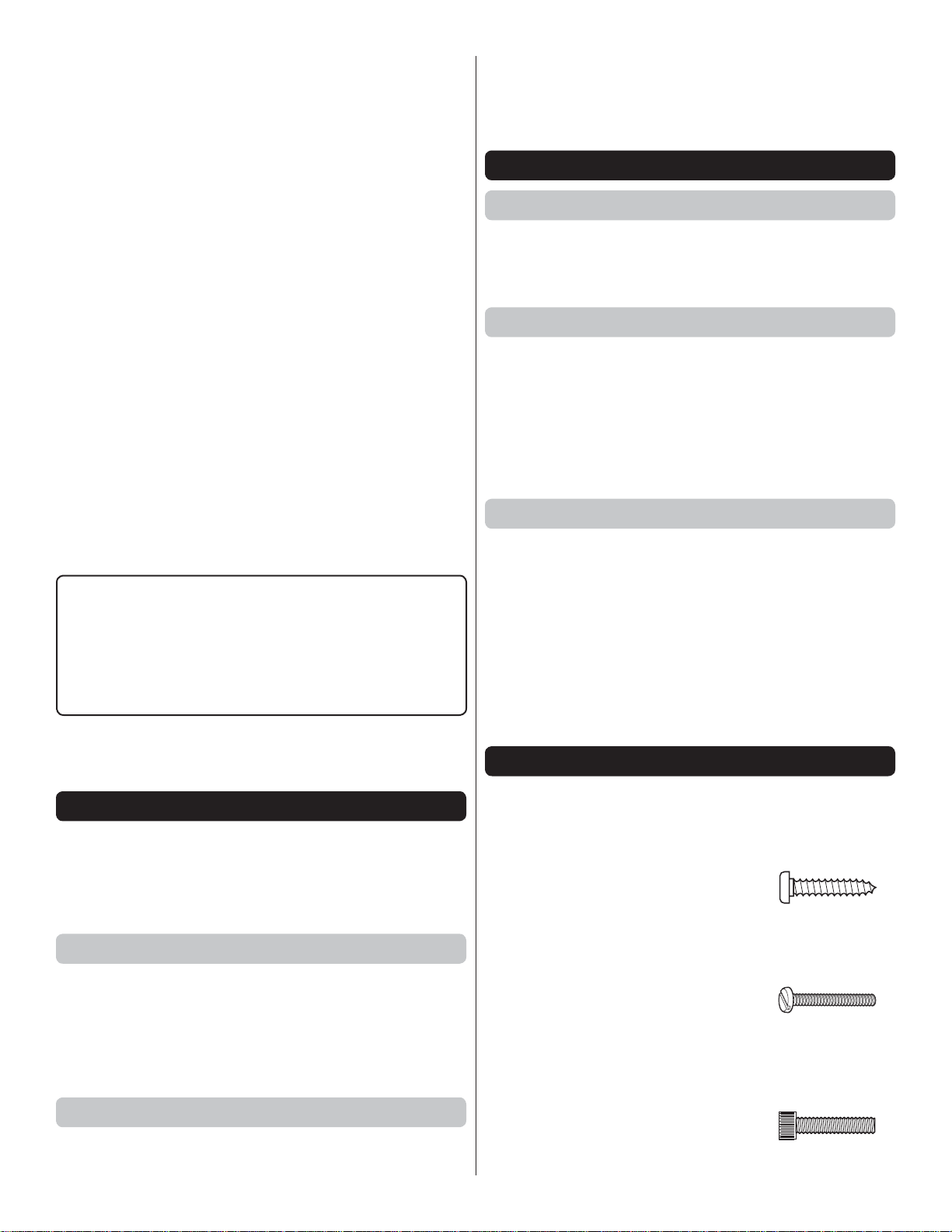
● There are three types of screws used in this kit:
Sheet Metal Screws are designated by a number and a
length. For example #6 × 3/4" [19mm].
This is a number six screw
that is 3/4" [19mm] long.
Machine Screws are designated by a number, threads
per inch, and a length. For example
4-40 × 3/4" [19mm].
This is a number four screw
that is 3/4" [19mm] long with
forty threads per inch.
Socket Head Cap Screws (SHCS) are designated by
a number, threads per inch, and a length. For example
4-40 × 3/4" [19mm].
This is a 4-40 SHCS that is
3/4" [19mm] long with forty
threads per inch
3
Page 4
● When you see the term test fi t in the instructions, it means
that you should fi rst position the part on the assembly
without using any glue, then slightly modify or custom
fi t the part as necessary for the best fi t.
To locate a hobby dealer, visit the Great Planes web site at
www.greatplanes.com. Select “Where to Buy” in the menu
across the top of the page and follow the instructions provided
to locate a U.S., Canadian or International dealer.
● Whenever the term glue is written you should rely upon
your experience to deci de what type of glue to use. When
a specifi c type of adhesive works best for that step, the
instructions will make a recommendation.
● Whenever just epoxy is specifi ed you may use either
30-minute (or 45-minute) epoxy or 6-mi nute epoxy. Wh en
30-minute epoxy is specifi ed it is highly recommended that
you use only 30-minute (or 45-minute) epoxy, because you
will need the working time and/or the additional strength.
● Photos and sketches are placed before the step they
refer to. Frequently you can study photos in following steps
to get another view of the same parts.
KIT IN SPE CTIO N
Before starting to build, take an inventory of this kit to make
sure it is complete, and inspect the parts to make sure they
are of acceptable quality. If any parts are missing or are not
of acceptable quality, or if you need assistance with assembly,
contact Pr oduct Support. When reporting defective or missing
parts, use the part names exactly as they are written in the
Kit Contents list.
Great Planes Product Support
3002 N Apollo Drive, Suite 1 Ph: (217) 398-8970, ext. 5
Champaign, IL 61822 Fax: (217) 398-7721
E-mail: airsupport@greatplanes.com
ORDERING REPLACEMENT PARTS
Replacement parts for the Great Planes Super Stearman EP
ARF are available using the order numbers in the Replacement
Parts List that follows. The fastest, most economical service
can be provided by your hob by dea ler or mail-ord er company.
Parts may also be ordered directly from Hobby Services by
calling (217) 398-0007, or via facsimile at (217) 398-7721, but
full retail prices and shipping and handling charges will apply.
Illinois and Nevada residents will also be charged sales tax.
If ordering via fax, include a Visa® or MasterCard® number
and expiration date for payment.
Mail parts orders Hobby Services
and payments by 3002 N Apollo Drive, Suite 1
personal check to: Champaign IL 61822
Be certain to specify the order number exactly as listed in the
Replacement Parts List. Payment by credit card or personal
check only; no C.O.D.
If additional assistance is required for any reason contact
Product Support by e-mail at productsupport@greatplanes.
com, or by telephone at (217) 398-8970.
REPLACEMENT PARTS LIST
Order No. Description
GPMA4500
GPMA4501
GPMA4502
GPMA4503
GPMA4504
GPMA4505
GPMA4506
GPMA4507
GPMA4508
GPMA4509
GPMA4510
GPMA4511
Top Wing Stearman EP ARF
Bottom Wing Stearman EP ARF
Fuselage Stearman EP ARF
Tail Set Stearman EP ARF
Cowl Stearman EP ARF
Landing Gear Stearman EP ARF
Gear Fairings Stearman EP ARF
Struts Stearman EP ARF
Cabanes Stearman EP ARF
Wheelpants Stearman EP ARF
Decals Stearman EP ARF
Hatch Stearman EP ARF
4
Page 5
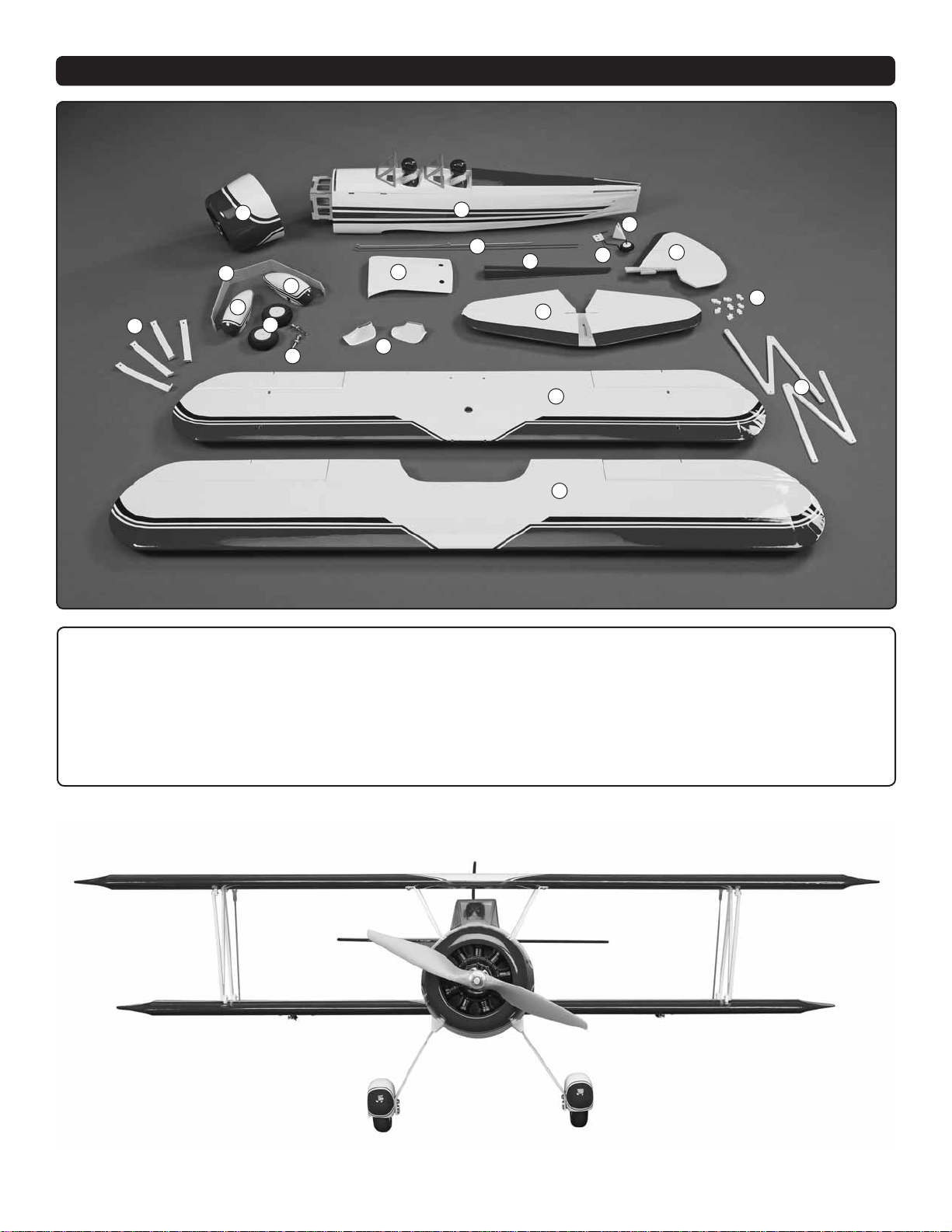
KIT CONTENTS
2
8
9
18
1. Fuselage
2. Cowl
3. Fin & Rudder
4. Tail Cone
5. Tail Wheel Assembly
6. Pushrod Wires
7. Belly Pan
1
6
9
10
11
7
12
19
13
16
17
8. Landing Gear
9. Wheel Pants
10. Wheels
11. Axles
12. Landing Gear Fairings
4
5
3
14
15. “N” Struts
16. Bottom Wing & Ailerons
17. Top Wing & Ailerons
18. Cabanes
19. Turtledeck
15
13. Stab & Elevator
14. Strut Mounting Tabs
5
Page 6
PREPARATIONS
Tighten the Covering
Refer to the separate instruction sheet titled How T o T igh ten
Covering On ARF Models. Follow the instructions to tighten
the covering. If you prefer to get started on assembly right
away, the tightening process could be done later (but it is
usually easiest to do while the model is still in separate pieces).
ASSEMBLE THE WINGS
Install the Aileron Servos & Pushrods
Do the right wing fi rst so your work matches the photos
the fi rst time through.
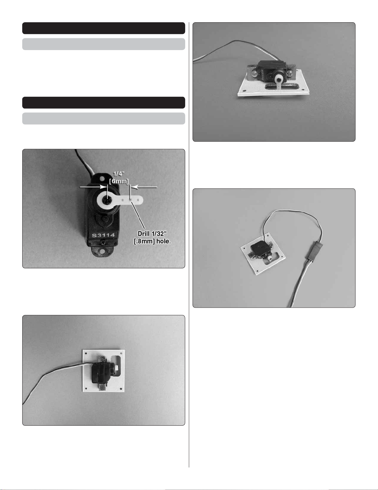
3. Place the servo between the mounting blocks. Drill
❏ ❏
a 1/16" [1.6mm] hole into each of the mounting blocks. (This
is the correct hole for Futaba mounting screws. Check your
screws and determine the size drill that is corr ect for it.) Secure
the servo to the blocks with the servo mounting screws.
1. Cut three arms from your servo horn so you have
❏ ❏
a single arm horn. Depending on your brand of servo the
length of the arms may vary. Choose an arm with a hole that
measures approximately 1/4" [6mm] from the center of the
servo to the hole. Enlarge the hole with a 1/32" [.8mm] drill bit.
2. Remove the aileron servo cover from the wing. Place
❏ ❏
the servo onto the inside of the cover, making sure the servo
arm is centered in the slot. Glue a 1/4" x 1/4" x 3/8" [6mm
x6mm x 9.5mm] hardwood block to the servo cover on each
side of the servo.
4. Install a 6" [152mm] servo extension onto the servo.
❏ ❏
Secure the connectors with heat shrink tubing included in
the kit. Do not skip this step. The holes that the lead goes
through in the wing are only slightly larger than the servo
connector. Not securing the connector could lead to the
leads unplugging when you pull the leads through the wing
in the next step.
6
Page 7
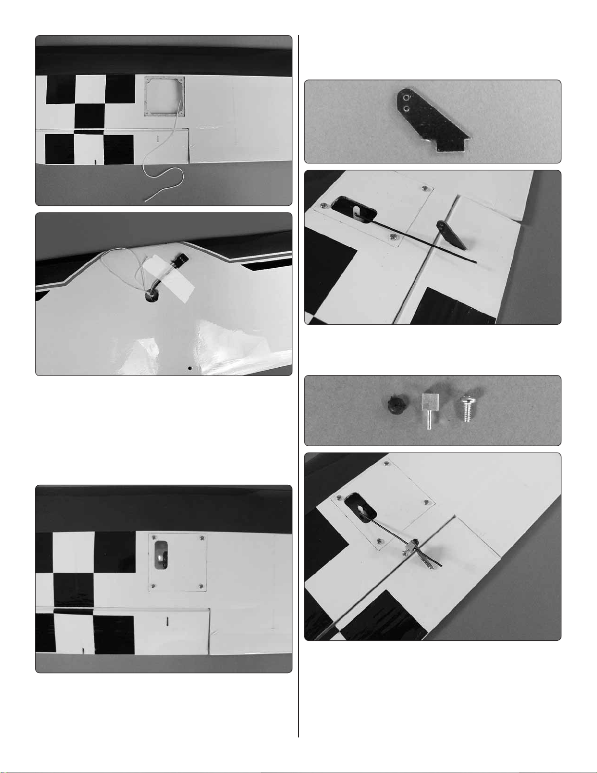
7. Install the z-bend end of a 5/64" x 6" [2mm x 152mm]
❏ ❏
aileron pushrod wire into the hole you drilled in the nylon
servo arm.
5. Inside of the servo bay you will fi nd a string taped.
❏ ❏
Pull the string out and tie the string to the servo extension
connector. Locate the hole in the top center of the wing.
Carefully pull the string with the lead attached to it through
the wing. Tape the servo lead to the wing to prevent it from
falling back into the wing. Important! The string is a single
string that extends to both of the servo openings. Be careful
not to pull the string loose from the other servo opening.
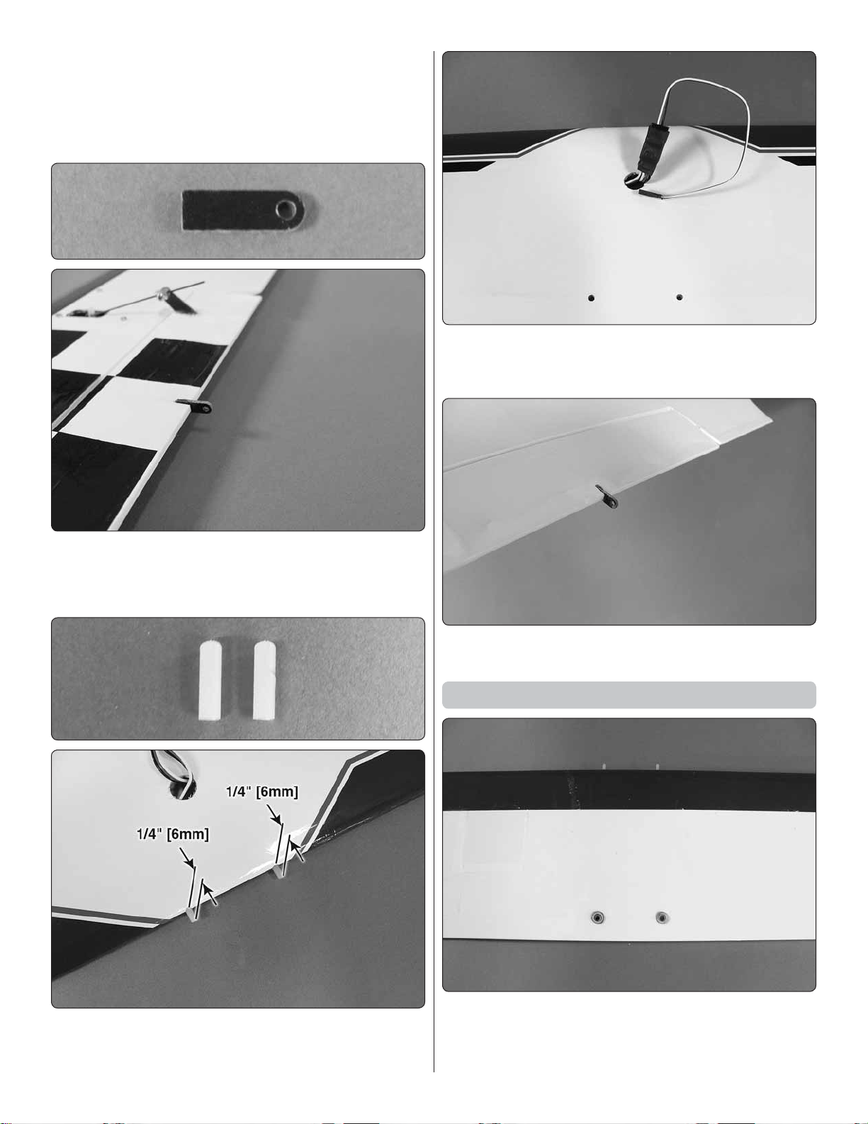
8. Locate a black control horn. Important! The hardware
❏ ❏
includes two different style horns. Be sure you use the horn
pictured here. Glue it into the slot in the aileron.
6. Secure the servo cover with four #2 x 5/16" [8mm]
❏ ❏
washer head screws. Before installing the cover, insert and
then remove a screw into the mounting holes in the servo bay.
Apply a drop of thin CA glue to harden the threads. After the
glue hardens install the servo cover.
9. Locate the aluminum screw-lock connector, black
❏ ❏
nylon retainer and the 2-56 x 3/16" [4.8mm] set screw. Test
fi t the screw lock connector into the outer most hole in the
aileron control horn. If it is too tight, enlarge the hole slightly
with the blade of a hobby knife. Be sure not to make the hole
too large. Remove the screw-lock connector from the control
horn. Slide the aluminum screw-lock connector onto the aileron
7
Page 8
pushrod wire and then insert the screw-lock connector into
the aileron control horn. Secure the connector with the black
nylon retainer. Center the aileron servo and the aileron. Apply
a drop of thread locker to the 2-56 x 3/16" [4.8mm] set screw
and then tighten the screw against the pushrod wire. Cut off
the excess pushrod wire, leaving 1/4" beyond the connector.
13. Connect the aileron to a Y-connector. Be sure to
❏
secure the connection with heat shrink tubing, tape or some
other method.
10. Glue one of the 1/2" [13mm] long aileron linkage
❏ ❏
rods into the slot in the aileron.
11. Repeat steps 1-10 for the left wing panel.
❏
14. Glue the remaining 1/2" [13mm] long aileron linkage
❏
rods into the slot in the ailerons on the top wing.
Install Stab, Elevators, Fin & Rudder
12. Locate two 1/8" x 3/8" [3mm x 10mm] nylon pins. Glue
❏
them into the holes in the leading edge of the bottom wing
leaving 1/4" [6mm] extending from the leading edge of the wing.
1. On the bottom wing, glue two plywood wing bolt doubler
❏
rings to the top center of the wing, centering them over the
wing bolt holes.
8
Page 9

2. Temporarily bolt the wing to the fuselage with two 4-40
❏
x 1" [25mm] bolts and #4 fl at washers.
3. Slide the wire elevator joiner into the stab opening
❏
6. Temporarily install the rudder into the opening in the stab.
❏
7. Measure the distance from the tips of the stab to the tips
❏
of the wing. Adjust the stab until they are equal.
4. Slide the stab into the stab opening making sure the
❏
wire stays in the opening.
5. Make sure the stab aligns with the wing. If it does not,
❏
lightly sand the stab saddle.
8. Carefully remove the fi n and rudder, making sure you
❏
do not disturb the stab. Wick CA glue into the joint, securing
the stab to the fuselage. Allow the glue to cure.
9
Page 10

9, Look at both elevator halves. You will see a slot in the
❏
left elevator. When installing the elevators in the next step,
be sure the elevator half with the slot is installed on the left
half of the stab and the slot is on the bottom of the elevator.
10. Locate four 3/8" x 5/8" [9mmx15mm] hinges. Insert a
❏
pin through the center of each hinge.
12. Test fi t the elevator to the stab, making sure to guide
❏
the elevator joiner wire into the hole in the leading edge of
the elevator. Check the alignment of both elevator halves. If
they are not in alignment remove the elevators and slightly
bend the joiner wire until the elevators are in line with each
other. Once satisfi ed with the fi t, remove the elevator half
and apply a small amount of epoxy to the end of the joiner
wire. Re-install the elevator and hinges to the stab. Apply
a couple of drops of thin CA to the top and bottom of each
hinge. Repeat this step for the other elevator half.
11. Insert a hinge into each of the hinge slots in the elevators.
❏
13. Locate the wire tail assembly. Test fi t the nylon bearing
❏
into the slot in the end of the fuselage. When you are satisfi ed
10
Page 11

with the fi t, apply a couple of drops of oil to the wire where
it passes through the bearing. This will prevent any glue
from getting into the nylon bearing. Apply a small amount of
30-minute epoxy to both sides of the nylon bearing and into
the slot in the fuselage. Install the bearing into the slot. Wipe
away excess epoxy with a paper towel and alcohol. Quickly
move on to the next step as it must be completed before
the epoxy on the tail wheel hardens.
15. Test fi t the tail wheel wire cone to the back of the
❏
fuselage. Using the tail cone as a reference, cut away a small
amount of covering from the back of the fuselage to create a
wood gluing surface for the tail cone.
14. Test fi t the rudder to the rudder tail wheel wire and slide
❏
the fi n into the slot in the fuselage. When satisfi ed with the fi t
remove the fi n and rudder. Apply a small amount of epoxy to
the uncovered portion of the fi n, into the slot in the fuselage
and to the tail wheel wire. Then, re-install the fi n and rudder.
Wipe any epoxy away with a paper towel and alcohol.
16. Glue the tail cone in place to the back of the fuselage.
❏
17. Slide the tail wheel onto the tail wheel wire. Secure
❏
it with the 1/8" [3mm] wheel collar and the 1/8" x 3/16" [3x
5mm] Phillips head screw.
11
Page 12

18. Included in the kit are two 15-3/4" [400mm] pushrod
❏
wires with a Z-bend on one end. The wires most likely have
some glue residue on them from the masking tape that held
them together. Clean off any residue with lighter fl uid, alcohol,
etc. Install the end of the wire with the Z-bend into the outer
hole of both control horns.
20. Repeat this for the rudder pushrod and control horn.
❏
Install Landing Gear, Wheels,
Wheel Pants & Turtledeck
19. Slide the wire into the hole on the side of the fuselage.
❏
Test fi t the control horn into the slot in the elevator. When you
are satisfi ed with the fi t, securely glue the horn into the slot
in the elevator.
1. Mount the landing gear to the bottom of the fuselage.
❏
Secure it to the fuselage with two 2-56 x 3/8" [9.5mm] machine
screws, #2 fl at washer s and #2 lock washer s. Be s ure to apply
a couple drops of thread locker to each of the screws before
installing them into the fuselage.
12
Page 13

2. Test fi t the landing gear fairings to the landing gear.
❏
(There is a right and left fairing. When properly installed you
will have access t o the landing gear moun ting scre ws. If the y
are mounted incorrectly the fair ing will cover the screw). After
determining the proper side of the landing gear to mount them
on, apply a bead of RC Z 56 glue along the inside bottom
edge of the fairing. Position the fairing on the fuselage and
tape it in place until the glue has dried. Do this for both fairings.
4. Install an axle into each of the landing gear legs and
❏
secure them with the 3/16" [5mm] axle lock nuts.
5. Slide two 3/16" [5mm] washers onto each axle followed
❏
by the wheel. Install a 6-32 x 1/8" [3mm] set screw into the
3/16" [5mm] wheel collars. Secure the wheel to the axles with
the wheel collar. Be sure to apply a couple of drops of thread
locker on the set screws.
3. Locate the plastic turtle deck. Apply a bead of RC Z 56
❏
glue along the inside bottom edge of the turtle deck. Position
the turtle deck onto the fuselage as shown and tape it in place
until the glue dries. Set the airplane aside to allow the glue
to dry on the fairings and the turtle deck.
6. Mount the wheel pants to the landing gear with two
❏
2-56 x 3/8" [9.5mm] machine screws, #2 lock washers and
#2 fl at washers. Be sure to apply a couple of drops of thread
locker onto each of the screws. Do this for both wheel pants.
13
Page 14

Install the Motor Speed Control,
Receiver & Servos
If you have the bottom wing installed, remove it. This will
make the following installation easier.
1. Included with your kit is self-adhesive Velcro®. Cut it
❏
into two equally sized pieces. Apply one half to the inside of
the fuselage as shown in the picture. Apply the other half to
the speed control.
2. Install the speed control onto the Velcro® you installed
❏
inside the fuselage. The motor leads should be fed through
the front of the fuselage.
3. Mount the motor to the fuselage with four 4-40 x 3/8"
❏
[9.5mm] machine screws, #4 lock washers and #4 fl at washers.
Be sure to apply a couple of drops of thread locker to the
screws.
14
Page 15

4. Two lengths of Velcro® are included with the kit to secure
❏
the battery. If you are using the recomended battery you will
only need to install Velcro® in the forward slots. Other size
and shaped batteries may require the use of the second piece.
Install the Velcro® as needed.
5. Center the servo and then install a screw lock connector,
❏
nylon retainer and 2-56 x 3/16" [2mmx 4.8mm] screw into the
center hole on the servo arm.
7. Install a longer servo arm on the rudder servo. The arm
❏
must be long enough so that you can install the screw lock
connector into a hole approximately 1/2" [13mm] from the
center of the servo spline. Install the screw lock connector,
retainer and 2-56 x 3/16" [2mmx 4.8mm] screw and then install
the rudder servo into the tray using the same technique used
for the elevator servo.
8. Cut off the excess pushrod wire, leaving 1/4" beyond
❏
the connector.
6. Install the elevator servo into the servo tray, sliding
❏
the pushrod wire into the screw lock connector. Drill a 1/16"
[1.6mm] hole through each of the servo mounting tab holes.
Install and remove the servo mounting screw. Apply a couple
drops of thin CA in the screw hole to harden the threads. Once
the glue has hardened, secure the servo with the mounting
screws that came with the servo.
9. Install the remaining self adhesive Velcro to the back of
❏
your receiver and the plywood tray as shown.
15
Page 16

10. Plug the servo and ESC leads into the appropriate
❏
channels of the receiver and then install the servo to the
tray. Route the antenna wire following the instructions with
the receiver.
Install Cabanes, Wings & Struts
1. Locate the four wing cabanes and lay them out as shown
❏
in the photo. It is important that you install the correct cabane
in the correct position in the fuselage. The shorter cabane
installs into the forward slots and the longer cabane installs
in the rear slots. Mark each of the cabanes to eliminate any
confusion while installing them.
11. Install the battery onto the tray, sliding the battery as far
❏
forward as possible. Secure the battery with the Velcro strap.
If you plugged the battery into the ESC, unplug it before
proceeding.
2. Slide the left side cabanes into the proper slots in the
❏
left side of the fuselage. Use the included allen wrench to
install a 2-56 x 1/4" [6mm] socket head cap screw into each
cabane. Be sure to use a couple of drops of thread locker
on each of the screws. When tightening the screws, tighten
them enough that they compress the balsa wood. This allows
the cabanes to be tight to the plywood on the opposite side
of the balsa. Repeat this for the right side of the fuselage.
16
Page 17

3. These pictures show how the cabanes look when they
❏
have been properly installed.
5, Bolt the bottom wing to the fuselage with two 4-40 x 1"
❏
wing bolts and #4 fl at washers.
6. Apply RC Z 56 glue to the bottom edge of the wing fairing.
❏
Position the fairing on the wing. Wipe away any excess glue
and then tape the fairing in place.
4. Attach the top wing to the cabanes with four 2-56 x 3/8"
❏
[9.5mm] machine screws. Be sure to use a couple of drops
of thread locker on each of the screws before installing them.
7. Locate the plywood strut attachment tabs. Cut all eight
❏
tabs from the tree.
17
Page 18

8. Each of the tabs is lettered “A”, “B” and “C”. Test fi t two
❏
“A” tabs into the forward slots in each side of the bottom wing
and two of the “C” tabs in the rear slots.
IMPORTANT: When you insert the tabs into the right side
of the wing, the letters that are stamped on the tabs must
face towards the fuselage. When you install the tabs on
the left side of the wing the letters on the tabs must face
towards the wing tip. Do not glue the tabs to the wing yet.
9. Test fi t two “B” tabs into the forward slots in the bottom
❏
of the top wing and two of the “C” tabs in the rear slots.
IMPORTANT: When you insert the tabs into the right side
of the wing, the letters that are stamped on the tabs must
face towards the fuselage. When you install the tabs on
the left side of the wing the letters on the tabs must face
towards the wing tip. Do not glue the tabs to the wing yet.
11. Locate one of the 5/64" x 6" [2mm x 150mm] wires
❏
with a Z-bend on one end and threads on the other. Thread a
nylon clevis onto the threaded end of the wire approximately
25 turns. Slide a silicone clevis keeper retainer onto the wire
and over the clevis. Install the end of the wire with the Z-bend
into the connector on the trailing edge of one of the ailerons
on the bottom wing. Center the bottom wing aileron and the
aileron on the top wing. Adjust the clevis on the wire until it
aligns with the hole in the connector in the top aileron. Once
aligned, snap the clevis onto the connector and secure it by
sliding the silicone clevis retainer over the clevis. Repeat this
for the other wing.
Final Assembly
10. The tabs fi t snug enough that they should remain in
❏
place without any glue. Secure the wing struts to the tabs
with four #2 x 5/16" [8mm] washer head screws. Once you
are satisfi ed everything fi ts well, remove the struts and then
glue the tabs into the slots. Once the glue has hardened
reinstall the struts.
1. Slide the cockpit into place on the fuselage. Slide it back
❏
allowing the magnets to lock it into place.
2. Slide the cowl into place, adjusting it as needed until
❏
the magnets lock it into place
3. Install the prop onto the motor shaft. Secure it in place
❏
with the washer and nut that came with the motor.
Apply the Decals
1. Be certain the model is clean and free from oily fi ngerprints
❏
and dust. Prepare a dishpan or small bucket with a mixture
of liquid dish soap and warm water—about one teaspoon of
soap per gallon of water. Submerse the decal in the soap and
water and peel off the paper backing. Note: Even though the
decals have a “sticky-back” and are not the water transfer type,
18
Page 19

submersing them in soap & water allows accurate positioning
FULL
THROTTLE
RUDDER
MOVES
RIGHT
ELEVATOR
MOVES DOWN
RIGHT AILERON
MOVES UP
LEFT AILERON
MOVES DOWN
4-CHANNEL RADIO SETUP
(STANDARD MODE 2)
and reduces air bubbles underneath.
2. Position decal on the model where desired. Holding the
❏
decal down, use a paper towel to wipe most of the water away.
3. Use a piece of soft balsa or something similar to
❏
squeegee remaining water from under the decal. Apply the
rest of the decals the same way.
GET TH E MODEL READY TO FLY
Install & Connect the Motor Battery
Before you can power the radio system and set up the controls,
the motor batteries will need to be charged. Charge the
batteries following the instructions with your battery and
charger.
4. If the prop is on the airplane remove it, the nut and
❏
washer. Arm the speed control and slowly start the motor. Be
sure the motor is turning in a counter clockwise direction as
observed from the front of the airplane. If it is not turning the
correct direction unplug two of the motor wires and reverse
them. Re-check that the motor is turning the correct direction.
Set the Control Throws
Check the Control Directions
1. Turn on the transmitter and receiver and center the trims.
❏
If necessary, remove the servo arms from the servos and
reposition them so they are centered. Reinstall the screws
that hold on the servo arms.
2. With the transmitter and receiver still on, check all the
❏
control surfaces to see if they are centered. If necessary, adjust
the clevises on the pushrods to center the control surfaces.
To ensure a successful fi rst fl ight, set up your Super
Stearman EP according to the control throws specifi ed in
this manual. The throws have been determined through
actual fl ight testing and accurate record-keeping, allowing
the model to perform in the manner in which it was intended.
If, after you have become accustomed to the way the Super
Stearman EP fl ies, you would like to change the throws
to suit your taste, that is fi ne. However, too much control
throw could make the model too responsive and diffi cult to
control, so remember, “more is not always better.”
1. Use a box or something similar to prop up the bottom of
❏
the fuselage so the horizontal stabilizer and wing will be level.
Measure the high rate elevator throw fi rst…
2. Hold a ruler vertically on your workbench against the
❏
widest part (front to back) of the trailing edge of the elevator.
Note the measurement on the ruler.
3. Make certain that the control surfaces respond in the
❏
correct direction as shown in the diagram. If any of the controls
respond in the wrong direction, use the servo reversing in the
transmitter to reverse the servos connected to those controls.
Be certain the control surfaces have remained centered.
Adjust if necessary.
3. Move the elevator up with your transmitter and move
❏
the ruler forward so it will remain contacting the trailing edge.
The distance the elevator moves up from center is the “up”
elevator throw. Measure the down elevator throw the same way.
19
Page 20

These are the recommended control surface throws:
LOW RATE
Up & Down
1/4"
ELEVATORRUDDERAILERONS
[6mm] 6°
Right & Left
7/8"
[22mm] 15°
Up & Down
1/4"
[6mm] 10°
If your radio does not have dual rates, we recommend set t ing
the throws at the low rate settings.
NOTE: The throws are measured at the widest par t of the
elevators, rudder and ailerons.
HIGH RATE
Up & Down
1/2"
[13mm] 12°
Right & Left
1-1/8"
[ 29 mm] 19°
Up & Down
3/8"
[10mm] 14°
Balance the Model (C.G.)
More than any other factor, the C.G. (center of gravity/
balance point) can have the greatest effect on how a model
fl ies and could determine whether or not your fi rst fl ight will
be successful. If you value your model and wish to enjoy it
for many fl ights, DO NOT OVERLOOK THIS IMPORTANT
PROCEDURE. A model that is not properly balanced may
be unstable and possibly unfl yable.
At this stage the model should be in ready-to-fl y condition
with all of the components in place including the complete
radio system, motor, battery and propeller.
3. If the tail drops, the model is “tail heavy.” If possible,
❏
move the battery pack and/or receiver forward to get the
model to balance. If the nose drops, the model is “nose heavy.”
If possible, move the battery pack and/or receiver aft. If the
re ceiver and / or batter y cannot be moved, or if ad ditiona l weig ht
is still required, nose weight may be easily added by using
use Great Planes “stick-on” lead (GPMQ4485). To fi nd out
how much weight is required, place incrementally increasing
amounts of weight on the top of the fuselage over the location
where it would be mounted inside until the model balances. A
good place to add stick-on nose weight is to the fi rewall. Do
not attach weight to the cowl. Once you have determined the
amount of weight required, it can be permanently attached.
4. IMPORTANT: If you found it necessary to add any
❏
weight, recheck the C.G. after the weight has been installed.
Balance the Model Laterally
1. With the wing level, have an assistant help you lift the
❏
model by the engine propeller shaft and the bottom of the
fuse under the TE of the fi n. Do this several times.
2. If one wing always drops when you lift the model, it means
❏
that side is heavy. Balance the airplane by adding weight
to the other wing tip. An airplane that has been laterally
balanced will track better in loops and other maneuvers.
PREFLIGHT
Identify Your Model
No matter if you fl y at an AMA sanctioned R/C club site or if
you fl y somewhere on your own, you should always have your
name, address, telephone number and AMA number on or
inside your model. It is required at all AMA R/C club fl ying sites
and AMA sanctioned fl ying events. Fill out the identifi cation
tag on page 23 and place it on or inside your model.
1. If using a Great Planes C.G. Machine™, set the rulers to
❏
2-5/8" [67mm]. If not using a C.G. Machine, use a fi ne-point
felt tip pen to mark lines on the top of wing on both sides of
the fuselage 2-5/8" [67mm] back from the leading edge. Apply
narrow (1/16" [2mm]) strips of tape over the lines so you will
be able to feel them when lifting the model with your fi ngers.
This is where your model should balance for the fi rst
fl ights. Later, you may experiment by shifting the C.G. 3/8"
[9.5mm] forward or 1/4" [6mm] back to change the fl ying
characteristics. Moving the C.G. forward will improve the
smoothness and stability, but the model will then be less
aerobatic (which may be fi ne for less-experienced pilots).
Moving the C.G. aft makes the model more maneuverable
and aerobatic for experienced pilots. In any case, start at
the recommended balance point and do not at any time
balance the model outside the specifi ed range.
2. With the wing attached to the fuselage and all parts of
❏
the model installed (ready to fl y), place the model on a Great
Planes CG Machine, or lift it at the balance point you marked.
Charge the Batteries
Follow the battery charging instructions that came with your
radio control system to charge the batteries. You should
always charge your transmitter batteries the night before you
go fl ying, and at other times as recommended by the radio
manufacturer.
CAUTION: Unless the instructions that came with your
radio system state differently, the initial charge on new
transmitter and receiver batteries should be done for 15
hours usi ng the slow-charger that came with the radio
system. This will “condition” the batteries so that the next
charge may be done using the fast-charger of your choice.
If the initial charge is done with a fast-charger the batteries
may not reach their full capacity and you may be fl ying with
batteries that are only partially charged.
20
Page 21

Balance Propellers
Carefully balance your propeller and spare propellers before
you fl y. A n unbal anced prop can b e the s ingle m ost sig nifi cant
cause of vibration that can damage your model. Not only
will engine mounting screws and bolts loosen, possibly with
disastrous effect, but vibration may also damage your radio
receiver and battery. Vibration can also cause your fuel to
foam, which will, in turn, cause your engine to run hot or quit.
We use a Top Flite Precision Magnetic Prop Balancer
(TOPQ5700) in the workshop and keep a Great Planes
Fingertip Prop Balancer (GPMQ5000) in our fl ight box.
AMA SAFETY COD E EXCERPTS
Read and abide by the following excerpts from the Academy
of Model Aeronautics Safety Code. For the complete Safety
Code refer to Model Aviation magazine, the AMA web site or
the Code that came with your AMA license.
General
1) I will not fl y my model aircraft in sanctioned events, air shows,
or model fl ying demonstrations until it has been proven to be
airworthy by having been previously, successfully fl ight tested.
2) I will not fl y my model aircraft higher than approximately
400 feet within 3 miles of an airport without notifying the
airport operator. I will give right-of-way and avoid fl ying in the
proximity of full-scale aircraft. Where necessary, an observer
shall be utilized to supervise fl ying to avoid having models fl y
in the proximity of full-scale aircraft.
3) Where established, I will abide by the safety rules for the
fl ying site I use, and I will not willfully and deliberately fl y my
models in a careless, reckless and/or dangerous manner.
5) I will not fl y my model unless it is identifi ed with my name
and address or AMA number, on or in the model. Note: This
does not apply to models while being fl own indoors.
Ground Check & Range Check
Always ground check the operational range of your radio
before the fi rst fl ight of the day following the manufacturer’s
instructions that came with your radio. This should be done
once with the motor off and once with the motor running
at various speeds. If the control surfaces do not respond
correctly, do not fl y! Find and correct the problem fi rst. Look
for loose servo connections or broken wires, corroded wires
on old servo connectors, poor solder joints in your battery
pack or a defective cell, or a damaged receiver crystal from
a previous crash.
MOTOR SAFETY PRECAUTIONS
Failure to follow these safety precaut ions m ay re sult
in severe injury to yourself and others.
● Get help from an experienced pilot when learning to operate
motors.
● Use safety glasses when starting or running engines.
● Do not run the motor in an area of loose gravel or sand;
the propeller may throw such material in your face or eyes.
7) I will not o p erate models with pyrotechnic s (any d evice that
explodes, burns, or propels a projectile of any kind).
Radio Control
1) I will have completed a successful radio equipment ground
check before the fi rst fl ight of a new or repaired model.
2) I will not fl y my model aircraft in the presence of spectators
until I become a qualified flier, unless assisted by an
experienced helper.
3) At all fl ying sites a straight or curved line(s) must be
established in front of which all fl ying takes place with the other
side for spectators. Only personnel involved with fl ying the
aircraft are allowed at or in front of the fl ight line. Intentional
fl ying behind the fl ight line is prohibited.
4) I will operate my model using only radio control frequencies
currently allowed by the Federal Communications Commission.
5) I will not knowingly operate my model within three miles
of any pre-existing fl ying site except in accordance with
the frequen cy sharing agr eement listed [in the complete
AMA Safety Code].
● Keep your face and body as well a s all sp e ctator s away fr om
the plane of rotation of the propeller as you run the motor.
● Keep these items away from the prop: loose clothing, shirt
sleeves, ties, scarfs, long hair or loose objects such as
pencils or screwdrivers that may fall out of shirt or jacket
pockets into the prop.
9) Under no circumstances may a pilot or other person touch
a powered model in fl ight; nor should any part of the model
other than the landing gear, intentionally touch the ground,
except while landing.
End of AMA Safety Code excerpts
21
Page 22

CHECK LIST
FLYING
During the last few moments of preparation your mind
may be elsewhere anticipating the excitement of the fi rst
fl ight. Because of this, you may be more likely to overlook
certain checks and procedures that should be performed
before the model is fl own. To help avoid this, a check list
is provided to make sure these important areas are not
overlooked. Many are covered in the instruction manual,
so where appropriate, refer to the manual for complete
instructions. Be sure to check the items off as they are
completed (that’s why it’s called a check list!).
1. Check the C.G. according to the measurements provided
❏
in the manual.
2. Be certain the battery and receiver are securely mounted
❏
in the fuse. Simply stuffi ng them into place with foam rubber
is not suffi cient.
3. If you use 72 MHz, extend your receiver antenna and
❏
make sure it has a strain relief inside the fuselage to keep
tension off the solder joint inside the receiver.
4. Balance your model laterally as explained in the
❏
instructions.
5. Use threadlocking compound to secure critical fasteners
❏
such as the set screws that hold the wheel axles to the struts,
screws that hold the carburetor arm (if applicable), screw-lock
pushrod connectors, etc.
6. Add a drop of oil to the axles so the wheels will turn freely.
❏
7. Make sure all hinges are securely glued in place.
❏
8. Reinforce holes for wood screws with thin CA where
❏
appropriate (servo mounting screws, cowl mounting
screws, etc.).
9. Confi rm that all controls operate in the correct direction
❏
and the throws are set up according to the manual.
10. Make sure there are silicone retainers on all the clevises
❏
and that all servo arms are secured to the servos with the
screws included with your radio.
11. Secure connections between servo wires and
❏
Y-connectors or servo extensions, and the connection between
your battery pack and the on/off switch, with vinyl tape, heat
shrink tubing or special clips suitable for that purpose.
12. Make sure any servo extension cords you may
❏
have used do not interfere with other systems (servo arms,
pushrods, etc.).
13. Balance your propeller (and spare propellers).
❏
14. Tighten the propeller nut and spinner.
❏
15. Place your name, address, AMA number and telephone
❏
number on or inside your model.
16. If you wish to photograph your model, do so before
❏
your fi rst fl ight.
The Great Planes Super Stearman EP is a great-fl ying model
that fl ies smoothly and predictably. The Super Stearman EP
does not, however, possess the self-recovery characteristics of
a primary R/C trainer and should be fl own only by experienced
R/C pilots.
CAUTION (THIS APPLIES TO ALL R/C AIRPLANES): If,
while fl ying, you notice an alarming or unusual sound such
as a low-pitched “buzz,” this may indicate control surface
fl utter. Flutter occurs when a control surface (such as an
aileron or elevator) or a fl ying surface (such as a wing or
stab) rapidly vibrates up and down (thus causing the noise).
In extreme cases, if not detected immediately, fl utter can
actually cause the control surface to detach or the fl ying
surface to fail, thus causing loss of control followed by
an impending crash. The best thing to do when fl utter is
detected is to slow the model immediately by reducing
power, then la nd as so on as safely possib le. Id entif y which
surface fl uttered (so the problem may be resolved) by
checking all the servo grommets for deterioration or signs of
vibration. Make certain all pushrod linkages are secure and
free of play. If it fl uttered once, under similar circumstances
it will probably fl utter again unless the problem is fi xed.
Some things which can cause fl utter are; Excessive hinge
gap; Not mounting control horns solidly; Poor fi t of clevis
pin in horn; Side-play of wire pushrods caused by large
be nds; Exce ssive free play in ser vo gear s ; Insecure ser vo
mounting; and one of the most prevalent causes of fl utter;
Flying an over-powered model at excessive speeds.
Takeoff
Before you get ready to takeoff, see how the model handles
on the ground by doing a few practice runs at low speeds
on the runway. Hold “up” elevator to keep the tail wheel on
the ground. If necessary, adjust the tail wheel so the model
will roll straight down the runway. If you need to calm your
nerves before the maiden fl ight, shut the motor down and bring
the model back into the pits. Top off the fuel, then check all
fasteners and control linkages for peace of mind.
Remember to takeoff into the wind. When you’re ready, point
the model straight down the runway, hold a bit of up elevator
to keep the tail on the ground to maintain tail wheel steering,
then gradually advance the throttle. As the model gains
speed decrease up elevator allowing the tail to come off the
ground. One of the most important things to remember with
a tail dragger is to always be ready to apply right rudder to
counteract engine torque. Gain as much speed as your runway
and fl ying site will practically allow before gently applying up
elevator, lifting the model into the air. At this moment it is likely
that you will need to apply more right rudder to counteract
engine torque. Be smooth on the elevator stick, allowing the
model to establish a gentle climb to a safe altitude before
turning into the traffi c pattern.
17. Range check your radio when you get to the fl ying fi eld.
❏
22
Page 23

Flight
For reassurance and to keep an eye on other traffi c, it is a
go o d idea to have an assi stant on the fl i ght line with you. Tell
him to remind you to throttle back once the plane gets to a
comfortable altitude. While full throttle is usually desirable for
takeoff, most models fl y more smoothly at reduced speeds.
Take it easy with the Stearman for the fi rst few fl ights, gradually
getting acquainted with it as you gain confi dence. Adjust the
trims to maintain straight and level fl ight. After fl ying around
for a while, and while still at a safe altitude with plenty of fuel,
practice slow fl ight and execute practice landing approaches
by reducing the throttle to see how the model handles at slower
speeds. Add power to see how she climbs as well. Continue to
fl y around, executing various maneuvers and making mental
notes (or having your assistant write them down) of what
trim or C.G. changes may be required to fi ne tune the model
so it fl ies the way you like. Mind your fuel level, but use this
fi rst fl ight to become familiar with your model before landing.
Landing
To initiate a landing approach, lower the throttle while on the
downwind leg. Allow the nose of the model to pitch downward
to gradually bleed off altitude. Continue to lose altitude, but
maintain airspeed by keeping the nose down as you turn onto
the crosswind leg. Make your fi nal turn toward the runway
(into the wind) keeping the nose down to maintain airspeed
and control. Level the attitude when the model reaches the
runway threshold, modulating the throttle as necessary to
maintain your glide path and airspeed. If you are going to
overshoot, smoothly advance the throttle (always ready on
the right rudder to counteract torque) and climb out to make
an other attempt. When you’re ready to make your landing fl are
and the model is a foot or so off the deck, smoothly increase
up elevator until it gently touches down. Once the model is
on the runway and has lost fl ying speed, hold up elevator
to place the tail on the ground, regaining tail wheel control.
One fi nal note about fl ying your model. Have a goal or fl ight
plan in mind for every fl ight. This can be learning a new
maneuver(s), improving a maneuver(s) you already know,
or learning how the model behaves in certain conditions
(such as on high or low rates). This is not necessarily to
improve your skills (though it is never a bad idea!), but more
importantly so you do not surprise yourself by impulsively
attempting a maneuver and suddenly fi nding that you’ve run
out of time, altitude or airspeed. Every maneuver should be
deliberate, not impulsive. For example, if you’re going to do a
loop, check your altitude, mind the wind direction (anticipating
rudder corrections that will be required to maintain heading),
remember to throttle back at the top, and make certain you
are on the desired rates (high/low rates). A fl ight plan greatly
reduces the chances of crashing your model just because
of poor planning and impulsive moves. Remember to think.
Have a ball! But always stay in control
and fl y in a safe manner.
GOOD LUCK AND GREAT FLYING!
Name
Address
City, State, Zip
This model belongs to:
23
AMA Number
Phone Number
Page 24

GPMA1150 MnlEntire Contents © 2011 Hobbico,® Inc. All rights reserved.
 Loading...