

Page 1
SPECIFICATIONS
Wingspan: 41.5 in [1055mm]
Wing Area: 270 sq in
[17.4dm
2
]
INSTRUCTION MANUAL
Wing
Loading:
Length: 31.5 in [800mm]
12.3-15.5 oz/ft
[38-47g/dm2]
®
Propeller: Great Planes
10x4.5
Slo-Flyer Electric Prop
2
ESC: ElectriFly™ SS-25
Battery: 11.1V, 1250-1600mAh LiPo
Weight: 23-29 oz
[650-820g]
Motor:
ElectriFly™
(28-30-950) Brushless
WARRANTY
Great Planes® Model Manufacturing Co. guarantees this kit to
be free from defects in both material and workmanship at the
date of purchase. This warranty does not cover any component
parts damaged by use or modification. In no case shall Great
Planes’ liability exceed the original cost of the purchased kit.
Further, Great Planes reserves the right to change or modify this
warranty without notice.
In that Great Planes has no control over the final assembly or
material used for final assembly, no liability shall be assumed nor
accepted for any damage resulting from the use by the user of
the final user-assembled product. By the act of using the
user-assembled product, the user accepts all resulting liability.
If the buyer is not prepared to accept the liability associated
with the use of this product, the buyer is advised to return
READ THROUGH THIS MANUAL BEFORE STARTING CONSTRUCTION. IT CONTAINS IMPORTANT
INSTRUCTIONS AND WARNINGS CONCERNING THE ASSEMBLY AND USE OF THIS MODEL.
RimFire™ 400
Radio: 4-Channel (minimum) with Micro
Receiver, three Micro Servos
this kit immediately in new and unused condition to the
place of purchase.
To make a warranty claim send the defective part or item to
Hobby Services at the address below:
Hobby Services
3002 N. Apollo Dr. Suite 1
Champaign IL 61822 USA
Include a letter stating your name, return shipping address, as
much contact information as possible (daytime telephone
number, fax number, e-mail address), a detailed description of
the problem and a photocopy of the purchase receipt. Upon
receipt of the package the problem will be evaluated as quickly
as possible.
Champaign, Illinois
(217) 398-8970, Ext 5
airsupport@greatplanes.com
Entire Contents © Copyright 2009 GPMA1149 Mnl
Page 2
TABLE OF CONTENTS
INTRODUCTION
INTRODUCTION . . . . . . . . . . . . . . . . . . . . . . . . . . . . . . . . 2
AMA . . . . . . . . . . . . . . . . . . . . . . . . . . . . . . . . . . . . . . . . . . 2
SAFETY PRECAUTIONS . . . . . . . . . . . . . . . . . . . . . . . . . 2
LITHIUM BATTERY HANDLING AND USAGE . . . . . . . . . 3
REQUIRED ITEMS . . . . . . . . . . . . . . . . . . . . . . . . . . . . . . 3
Radio Equipment . . . . . . . . . . . . . . . . . . . . . . . . . . . . 3
Motor, ESC and Propeller . . . . . . . . . . . . . . . . . . . . . . 3
Battery Pack and Accessories . . . . . . . . . . . . . . . . . . 4
Required Adhesive and Building Supplies . . . . . . . . . 4
Optional Supplies and Tools . . . . . . . . . . . . . . . . . . . . 4
Pilot Figure (Optional) . . . . . . . . . . . . . . . . . . . . . . . . . 4
IMPORTANT BUILDING NOTES . . . . . . . . . . . . . . . . . . . . 4
KIT INSPECTION . . . . . . . . . . . . . . . . . . . . . . . . . . . . . . . 5
KIT CONTENTS . . . . . . . . . . . . . . . . . . . . . . . . . . . . . . . . 5
ORDERING REPLACEMENT PARTS . . . . . . . . . . . . . . . . 6
BEFORE YOU BEGIN . . . . . . . . . . . . . . . . . . . . . . . . . . . . 6
ASSEMBLE THE WINGS . . . . . . . . . . . . . . . . . . . . . . . . . 6
Join the Wings . . . . . . . . . . . . . . . . . . . . . . . . . . . . . . . 6
Install the Aileron Servo . . . . . . . . . . . . . . . . . . . . . . . 7
Install the Main Landing Gear . . . . . . . . . . . . . . . . . . . 9
INSTALL THE TAIL . . . . . . . . . . . . . . . . . . . . . . . . . . . . . 10
Install the Horizontal Stabilizer and Elevators . . . . . . 10
Install the Vertical Stabilizer, Rudder and Tailwheel . 11
INSTALL THE ELEVATOR and RUDDER SERVOS . . . . 12
INSTALL THE MOTOR, ESC, RECEIVER, & BATTERY . 15
FINISH THE MODEL . . . . . . . . . . . . . . . . . . . . . . . . . . . . 16
PILOT INSTALLATION (Optional) . . . . . . . . . . . . . . . . . . 18
APPLY THE DECALS . . . . . . . . . . . . . . . . . . . . . . . . . . . 19
GET THE MODEL READY TO FLY . . . . . . . . . . . . . . . . . 19
Check the Control Directions . . . . . . . . . . . . . . . . . . 19
Set the Control Throws . . . . . . . . . . . . . . . . . . . . . . . 19
Balance the Model (C.G.) . . . . . . . . . . . . . . . . . . . . . 20
Balance the Model Laterally . . . . . . . . . . . . . . . . . . . 21
PREFLIGHT . . . . . . . . . . . . . . . . . . . . . . . . . . . . . . . . . . 21
Identify Your Model . . . . . . . . . . . . . . . . . . . . . . . . . . 21
Charge the Batteries . . . . . . . . . . . . . . . . . . . . . . . . . 21
Balance Propellers . . . . . . . . . . . . . . . . . . . . . . . . . . 21
Range Check . . . . . . . . . . . . . . . . . . . . . . . . . . . . . . 21
MOTOR SAFETY PRECAUTIONS . . . . . . . . . . . . . . . . . 22
AMA SAFETY CODE . . . . . . . . . . . . . . . . . . . . . . . . . . . 22
General . . . . . . . . . . . . . . . . . . . . . . . . . . . . . . . . . . . 22
Radio Control . . . . . . . . . . . . . . . . . . . . . . . . . . . . . . 22
CHECK LIST . . . . . . . . . . . . . . . . . . . . . . . . . . . . . . . . . . 22
FLYING . . . . . . . . . . . . . . . . . . . . . . . . . . . . . . . . . . . . . . 23
Takeoff . . . . . . . . . . . . . . . . . . . . . . . . . . . . . . . . . . . . 23
Flight . . . . . . . . . . . . . . . . . . . . . . . . . . . . . . . . . . . . . 23
Landing . . . . . . . . . . . . . . . . . . . . . . . . . . . . . . . . . . . 24
Thank you for purchasing the Great Planes® PT-19 EP park
fl yer. We hope you enjoy the docile characteristics of this
classic model. PT stands for “Primary Trainer”, but don’t
let this fool you into thinking you can handle fl ying if you’ve
never been trained. Just as you wouldn’t simply jump into a
full-scale airplane and fl y away, trainer or not, you shouldn’t
do the same with a sophisticated R/C model like this. If you
don’t already know how to fl y, you should seek the help of
an experienced R/C pilot. There are also many training tools
available to help you learn to fl y R/C. Please see your local
hobby dealers for their recommendations.
For the latest technical updates or manual corrections to the
PT-19 EP visit the Great Planes web site at www .greatplanes.
com. Open the “Airplanes” link, then select the PT-19 EP
ARF. If there is new technical information or changes to this
model a “tech notice” box will appear in the upper left corner
of the page.
AMA
If you are not already a member of the AMA, please join!
The AMA is the governing body of model aviation and
membership provides liability insurance coverage, protects
modelers’ rights and interests and is required to fl y at most
R/C sites.
Academy of Model Aeronautics
5151 East Memorial Drive
Muncie, IN 47302
Tele: (800) 435-9262
Fax (765) 741-0057
Or via the Internet at: http://www.modelaircraft.org
IMPORTANT!!! Two of the most important things you can do
to preserve the radio controlled aircraft hobby are to avoid
fl ying near full-scale aircraft and avoid fl ying near or over
groups of people.
PROTECT YOUR MODEL, YOURSELF
& OTHERS… FOLLOW THESE
IMPORTANT SAFETY PRECAUTIONS
1. Your PT -19 EP should not be considered a toy, but rather
a sophisticated, working model that functions very much like
a full-size airplane. Because of its performance capabilities,
the PT-19 EP, if not assembled and operated correctly, could
possibly cause injury to yourself or spectators and damage
to property.
2
Page 3

2. You must assemble the model according to the
instructions. Do not alter or modify the model, as doing
so may result in an unsafe or unfl yable model. In a few
cases the instructions may differ slightly from the photos.
In those instances the written instructions should be
considered as correct.
3. You must take time to build straight, true and strong.
● ONLY charge through the “charge” lead. NEVER charge
through the “discharge” lead.
● NEVER charge at currents greater than 1C.
● ALWAYS set charger’s output volts to match battery volts.
● ALWAYS charge in a fi reproof location.
● NEVER trickle charge.
4. You must use an R/C radio system that is in fi rst-class
condition, and a correctly sized motor and components
throughout the building process.
5. You must correctly install all R/C and other components
so that the model operates correctly on the ground and in
the air.
6. You must check the operation of the model before every
fl ight to insure that all equipment is operating and that the
model has remained structurally sound. Be sure to check
clevises or other connectors often and replace them if they
show any signs of wear or fatigue.
7. If you are not an experienced pilot or have not fl own
this type of model before, we recommend that you get the
assistance of an experienced pilot in your R/C club for
your fi rst fl ights. If you’re not a member of a club, your local
hobby shop has information about clubs in your area whose
membership includes experienced pilots.
8. While this kit has been fl ight tested to exceed normal use,
if the plane will be used for extremely high stress fl ying, such
as racing, or if a motor larger than one in the recommended
range is used, the modeler is responsible for taking steps to
reinforce the high stress points and/or substituting hardware
more suitable for the increased stress.
We, as the kit manuf acturer, provide you with a top quality,
thoroughly tested kit and instructions, but ultimately the
quality and fl yability of your fi nished model depends
on how you build it; therefore, we cannot in any way
guarantee the performance of your completed model,
and no representations are expressed or implied as to the
performance or safety of your completed model.
Remember: Take your time and follow the instructions to
end up with a well-built model that is straight and true.
● NEVER allow battery temperature to exceed 150° F
(65° C).
● NEVER disassemble or modify pack wiring in any way or
puncture cells.
● NEVER discharge below 3.0V per cell.
● NEVER place on combustible materials or leave
unattended during charge or discharge.
● ALWAYS KEEP OUT OF REACH OF CHILDREN.
REQUIRED ITEMS
This is a partial list of items required to fi nish the PT-19 EP.
Order numbers are provided in parentheses.
Radio Equipment
A 4-channel radio system with three micro servos and a micro
receiver are required for this plane. Many radio systems are
suitable, but we have chosen the following for this build-up.
❍ (3) Futaba® S3114 Micro HT Servo (FUTM0414)
OR
❍ (3) minimum 20 oz-in torque micro servos
❍ Servo Mounting Screws (FUTM2250)
❍ Futaba R617FS 7-channel 2.4GHz Receiver
OR
❍ Futaba R114F FM Micro Receiver
(Low Band – FUTL0442, High Band – FUTL0443)
❍ Futaba FM Single Conversion Short Crystal
(Low Band – FUTL62**, High Band – FUTL63**)
LITHIUM BATTERY
HANDLING & USAGE
WARNING!! Read the entire instruction sheet included with
the battery. Failure to follow all instructions could cause
permanent damage to the battery and its surroundings, and
cause bodily harm!
● ONLY use a LiPo approved charger.
● NEVER charge in excess of 4.20V per cell.
Motor, ESC & Propeller
Recommendations
The PT-19 EP was tested e xtensively to fi nd the best “power
package” that offers light weight, long fl ight time, and good
thrust. The order numbers for these are provided below.
❍ Great Planes RimFire™ 400 (28-30-950) Brushless
Outrunner Motor (GPMG4560)
❍ Great Planes Silver Series 25A Brushless ESC 5V/2A
BEC (GPMM1820)
3
Page 4

❍ Great Planes 10x4.5 PowerFlow™ Propeller
(GPMQ6660) (draws 15 amps max.)
Optional Supplies and Tools
❍ Great Planes 3.5mm Male/2.5mm Female Bullet
Connector Adapter (GPMM3122)
Battery Pack & Accessories
The following battery packs are recommended.
❍ Great Planes LiPo 1600mAh BP Series 11.1V 20C
Discharge w/ Balance (GPMP0719)
❍ Great Planes LiPo 1500mAh Power Series 11.1V 25C
Discharge w/ Balance (GPMP0511)
A LiPo-compatible charger is required for these batteries,
along with a cell balancer. We recommend:
❍ Great Planes Equinox™ 1-5 cell LiPo cell balancer
(GPMM3160)
❍ Great Planes PolyCharge4™ LiPo battery charger
(GPMM3015)
OR
❍ Great Planes PolyCharge DC LiPo battery charger
(GPMM3010)
Required Adhesive and
Building Supplies
This is the list of adhesive and building supplies required to
fi nish the PT-19 EP.
❍ 1/2 oz. [15g] Thin Pro™ CA (GPMR6001)
❍ 1/2 oz. [15g] Medium Pro CA+ (GPMR6007)
❍ 4oz [113g] Pro 6-minute epoxy (GPMR6042)
❍ 4oz [113g] Pro 30-minute epoxy (GPMR6043)
❍ R/C-56 Glue 4oz (JOZR5007)
❍ Denatured alcohol
❍ Drill bits: #55 [1.3mm] [1.3mm], 1/16" [1.6mm],
5/64" [2mm], 1/8" [3.2mm]
❍ #1 Hobby knife (HCAR0105)
❍ #11 blades (5-pack, HCAR0211)
❍ Hobbico Steel T-Pins 1" (100) (HCAR5100)
❍ Great Planes Pro Thread locker (GPMR6060)
❍ CA applicator tips (HCAR3780)
❍ 220 grit sandpaper
❍ Masking tape (TOPR8018)
❍ Bru Line hemostat – curved 5-1/2" (BRUR1303)
❍ Fabric Tape Measure (HCAR0478)
Here is a list of optional tools mentioned in the manual that
will help you build the PT-19 EP.
st
❍ 21
Century® sealing iron (COVR2700)
❍ 21st Century iron cover (COVR2702)
❍ 2 oz. [57g] spray CA activator (GPMR6035)
❍ 4 oz. [113g] aerosol CA activator (GPMR634)
❍ Epoxy brushes (6, GPMR8060)
❍ Mixing sticks (50, GPMR8055)
❍ Mixing cups (GPMR8056)
❍ Great Planes® Hook and Loop material (GPMQ4480)
❍ 1/2" [13mm] double-sided foam mounting tape
(GPMQ4440)
❍ Excel Small Hobby Clamps (2) 1" x 3.5" [25 x 89mm]
(EXLR5663)
❍ CA debonder (GPMR6039)
❍ Great Planes Double-Sided Servo Tape 1"x 3’
(GPMQ4442)
❍ Panel Line Pen (TOPQ2510)
❍ Rotary tool (Dremel®) with cutoff wheel
❍ Hobbico® Flexible 18" Ruler Stainless Steel (HCAR0460)
❍ Builder’s Triangle Set (HCAR0480)
❍ AccuThrow™ Defl ection Gauge (GPMR2405)
❍ Hobbico 12 Volt DC power supply (HCAP0250)
❍ Acrylic paint and paint brushes for painting pilot (found at
craft stores)
Pilot Figure (optional)
The following pilot fi gures are suggested. Note: The
pre-painted pilot listed below is slightly larger than the
recommended Williams Brothers pilot fi gure and is a WWI
pilot.
❍ Williams Brothers 1/8-Scale Pilot Kit Standard
(WBRQ1040)
OR
❍ Great Planes Small EP WWI Pilot, Pre-Painted
(GPMA2998)
IMPORTANT BUILDING NOTES
● When you see the term test fi t in the instructions, it means
that you should fi rst position the part on the assembly
without using any glue, then slightly modify or custom fi t
the part as necessary for the best fi t.
4
Page 5
● Whenever the term glue is written you should rely upon
your experience to decide what type of glue to use. When
a specifi c type of adhesive works best for that step, the
instructions will make a recommendation.
● Photos and sketches are placed before the step they
refer to . Frequently y ou can study photos in follo wing steps
to get another view of the same parts.
● The stabilizer, wing incidences, and motor thrust angles
have been factory-built into this model. However, some
technically-minded modelers may wish to check these
measurements anyway. To view this information visit the
web site at www.greatplanes.com and click on “Technical
Data.” Due to manufacturing tolerances which will have
little or no effect on the way your model will fl y, please
expect slight deviations between your model and the
published values.
®
● The PT -19 EP is f actory-covered with T op Flite
MonoKote®
fi lm. Should repairs ever be required, MonoKote can be
patched with additional MonoKote purchased separately.
MonoKote is packaged in six-foot rolls, but some hobby
shops also sell it by the foot. If only a small piece of
MonoKote is needed for a minor patch, perhaps a fellow
modeler would give you some. MonoKote is applied with
a model airplane covering iron, but in an emergency a
regular iron could be used. A roll of MonoK ote includes full
instructions for application. Following are the colors used
on this model and order numbers for six foot rolls.
Yellow TOPQ0203
Sapphire Blue TOPQ0226
Missile Red TOPQ0201
Jet White TOPQ0204
Black TOPQ0208
KIT INSPECTION
Before starting to build, take an inventor y of this kit to make
sure it is complete, and inspect the parts to make sure they
are of acceptable quality . If any parts are missing or are not of
acceptable quality, or if you need assistance with assembly,
contact Product Support. When reporting defective or
missing parts, use the part names exactly as they are written
in the Kit Contents list.
Great Planes Product Support
3002 N Apollo Drive, Suite 1
Champaign, IL 61822
Telephone: (217) 398-8970, ext. 5
Fax: (217) 398-7721
E-mail: airsupport@greatplanes.com
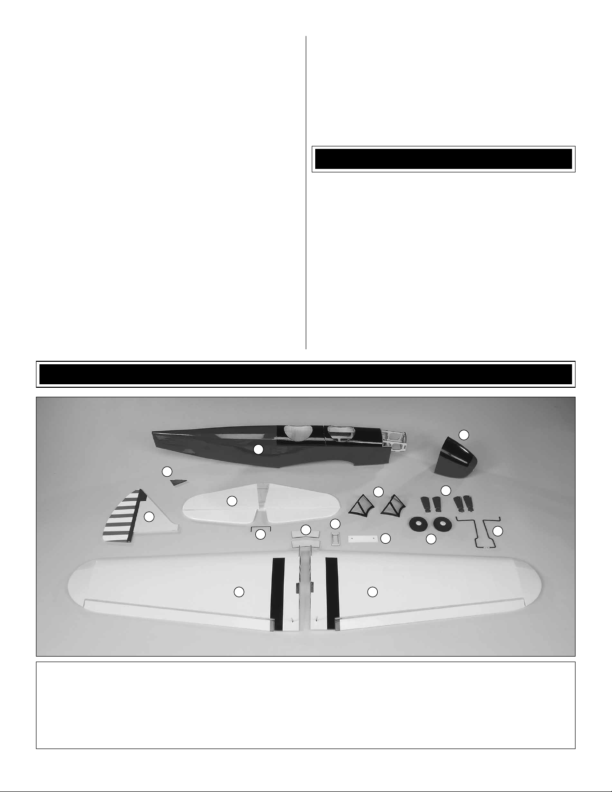
KIT CONTENTS
2
1
3
5
4
6
14 15
12
11
7
13
8
9
10
1. Fuselage
2. Cowl
3. Tail Skid
4. Vertical Fin & Rudder
5. Horizontal Stabilizer & Elevators
6. Elevator Joiner
7. Windscreens
8. Landing Gear Pants
9. Wheels
10. Main Landing Gear Legs
5
11. Wing Joiners
12. Servo Mounting Plate
13. Wing Bolt Plate
14. Left Wing
15. Right Wing
Page 6
ORDERING REPLACEMENT PARTS
Replacement parts for the Great Planes PT-19 EP ARF are
available using the order n umbers in the Replacement Parts
List that follows. The fastest, most economical service can
be provided by your hobby dealer or mail-order company.
To locate a hobby dealer, visit the Great Planes web site
at www.greatplanes.com. Select “Where to Buy” in the
menu across the top of the page and follow the instructions
provided to locate a U.S., Canadian or International dealer.
Parts may also be ordered directly from Hobby Services by
calling (217) 398-0007, or via facsimile at (217) 398-7721,
but full retail prices and shipping and handling charges will
apply. Illinois and Nevada residents will also be charged
sales tax. If ordering via fax, include a Visa
number and expiration date for payment.
Mail parts orders and payments by personal check to:
Hobby Services
3002 N Apollo Drive, Suite 1
Champaign IL 61822
®
or MasterCard®
BEFORE YOU BEGIN
Before you begin assembling your model, inspect it for
wrinkled covering and areas where the covering may not
be tacked down adequately. The covering should be tacked
down to the wood using just enough heat to soften the
adhesive backing. Low heat (about 250° F [121° C]) should
be enough to accomplish this. More heat may be required to
begin to tighten the covering.
ASSEMBLE THE WINGS
Be certain to specify the order number exactly as listed in
the Replacement Parts List. Payment by credit card or
personal check only; no C.O.D.
If additional assistance is required for any reason contact
Product Support by e-mail at productsupport@greatplanes.
com, or by telephone at (217) 398-8970.
REPLACEMENT PARTS LIST
Order No. Description
GPMA4000
GPMA4001
GPMA4002
GPMA4003
GPMA4004
GPMA4005
NOTE
Fuselage
Wing
Tail Surface Set
Landing Gear Set
Cowl
Decal
Full-size plans are not available.
You can download a copy of this
manual at www.hobbico.com.
Join the Wings
1. For the next few steps you will need epoxy, mixing
❏
cups, mixing sticks, and a few epoxy brushes. You should
also have some denatured alcohol and paper towels on
hand for cleanup.
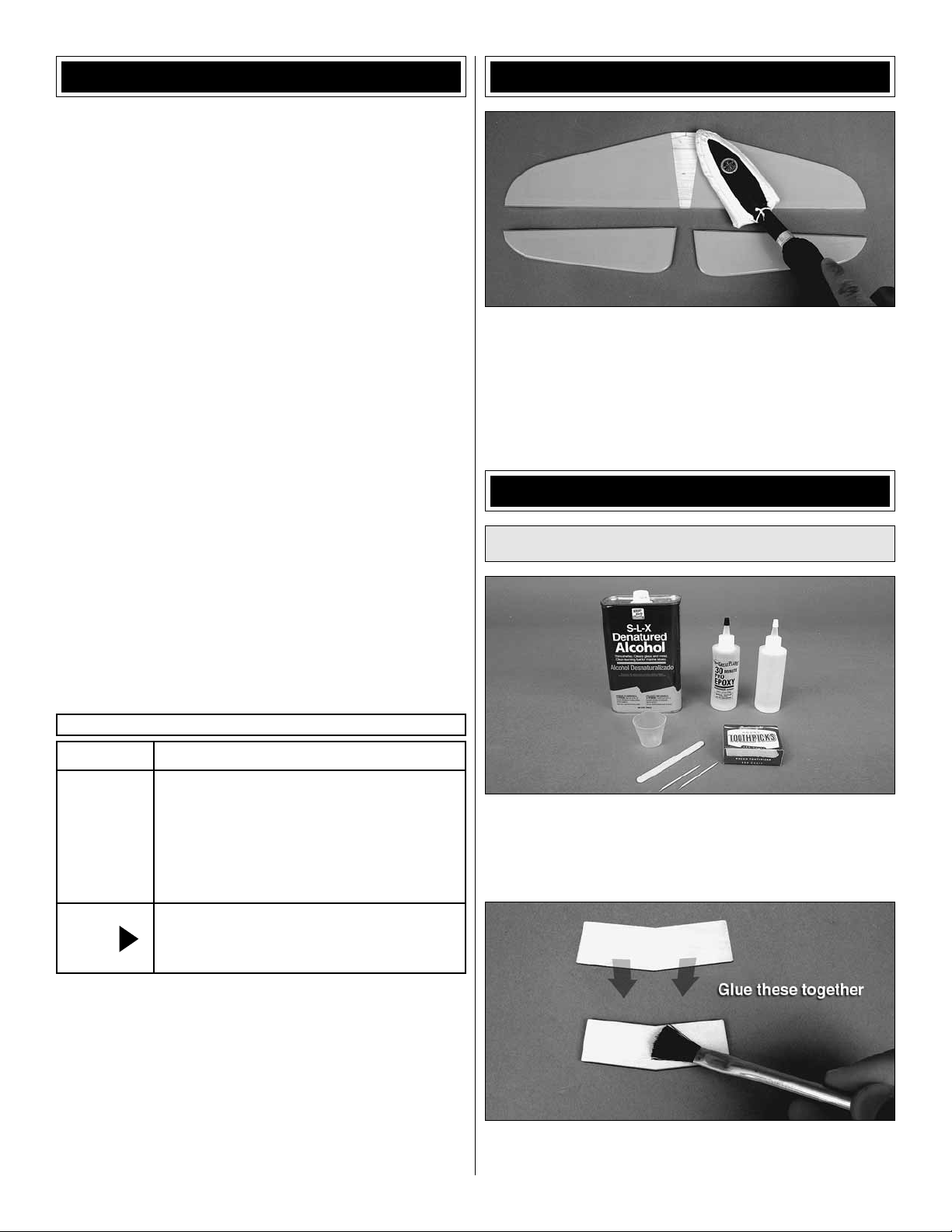
2. Mix up a small batch of 6-minute epoxy and glue the
❏
2mm thick wing joiner and 3mm thick wing joiner together
6
Page 7
so that one overlies the other. You now have a single 5mm
thick wing joiner.
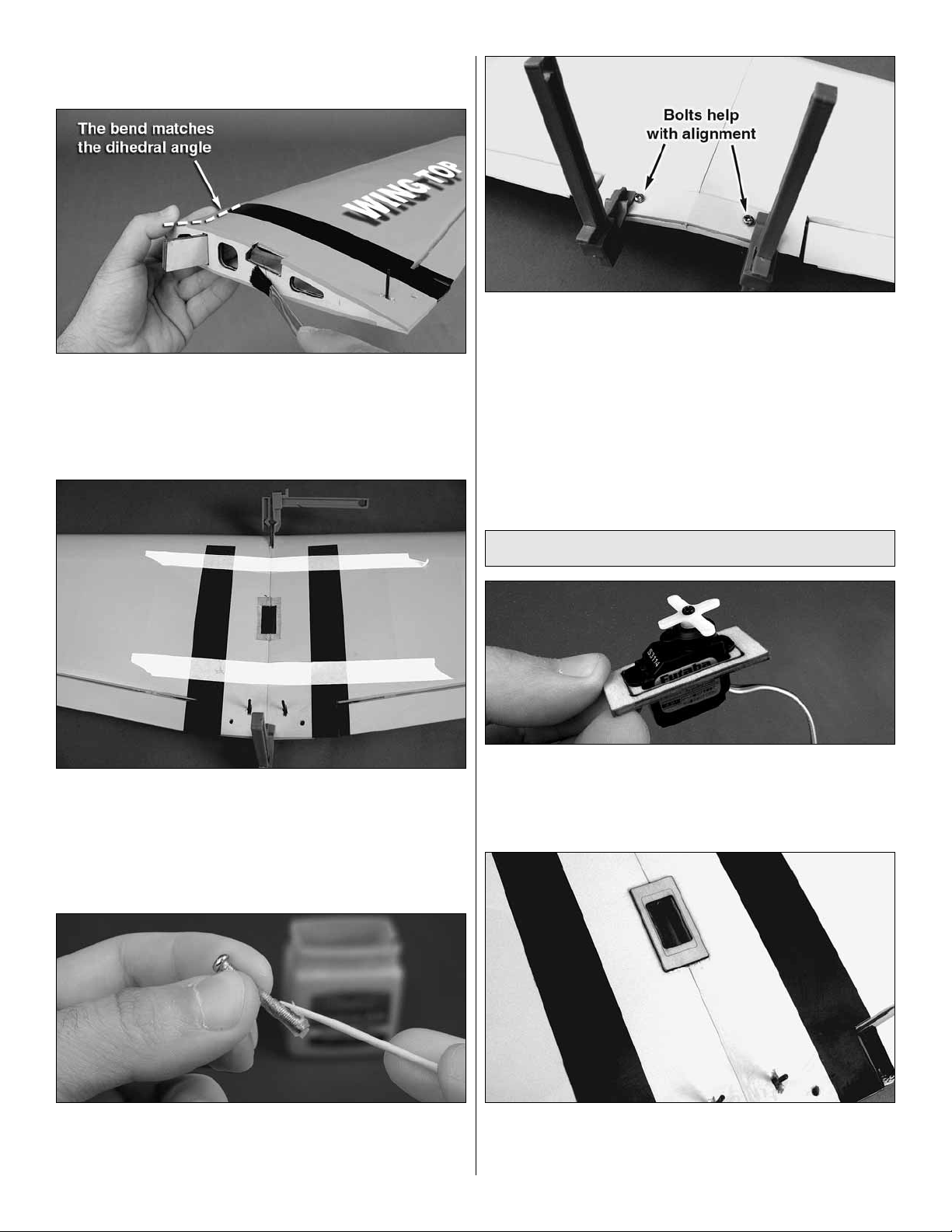
3. Coat both faces of the wing joiner with 30-minute epo xy
❏
and fi t the joiner into the slot in one wing so that the bend
in the joiner matches the dihedral angle of the root wing rib.
Coat the root rib of both wings. Note: The top of the wing is
the side of the wing that the torque rod exits.
6. After the epo xy cures, remo v e the clamps and the tape
❏
from the wing. Turn the wing over. Apply some 6-minute
epoxy to the wing bolt plate and glue it to the bottom side of
the wing. Use the two wing bolts to align the plate with the
holes in the wing. Clamp the wing bolt plate to the wing and
clean up any epoxy that squeezes out of the joint. Allow the
epoxy to fully cure.
7. Remove the clamps and wing bolts. Clean up the
❏
bolts with denatured alcohol and set them aside with your
other hardware.
4. Join both wings tightly. Clean up any epoxy that
❏
squeezes out of the joint with paper towels and denatured
alcohol. Hold the wings together tightly with at least f our long
strips of masking tape. Use two on the top and two on the
bottom. Use tw o small clamps to hold the wings in alignment
as the epoxy cures.
Install the Aileron Servo
1. Test fi t a ser vo in the aileron servo mounting plate. If
❏
you are using a servo larger than a Futaba 3114 micro servo,
use a Dremel® rotary tool or your hobby knife to enlarge the
opening in the plate to accommodate your particular servo.
5. Locate the two 3mm x 25mm wing bolts. Thoroughly
❏
coat the threads of each bolt with petroleum jelly (Vaseline®
or similar).
2. Center the ser vo mounting plate over the hole in the
❏
top of the wing. Epoxy the servo mounting plate in place. Be
careful to center it.
7
Page 8
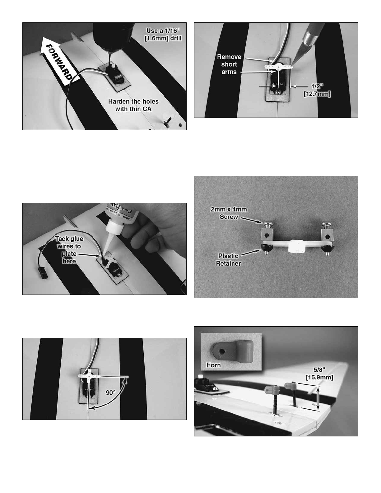
3. Remove the servo arm from the servo. Install your aileron
❏
servo so that the output shaft is oriented forward. Route the
lead through the mounting plate on one side of the servo so
that it does not interfere with the servo arms. Note: You may
have to trim a notch for the wire to pass through. Use a 1/16"
[1.6mm] drill to make holes for the servo screws. Install the
screws and then remove them. Remove the servo and place a
drop of thin CA into each screw hole you just tapped.
4. Reinstall the servo, making sure to route the servo lead
❏
properly . To keep the servo lead clear of the servo arms, tack
glue the lead to the servo mounting plate using one drop of
medium CA.
6. Use a #55 [1.3mm] drill to enlarge the two servo arm
❏
holes that are 1/2" [12.7mm] from the center of the output
shaft. These are the outermost holes of the standard servo
arm. If you don’t have a #55 [1.3mm] drill bit, you can use
your hobby knif e to carefully enlarge the hole until the screwlock pushrod connector pin fi ts.
7. Install a screw-lock pushrod connector to each servo
❏
arm and secure each one with a plastic retainer.
5. Using your radio system, center your aileron servo. Fit
❏
your servo arm to the splined servo shaft and fi nd the position
on the splines that allows the two long arms to be 90° to the
servo case. Clip off the other two servo arms. To save time,
you can plug your other two servos into your receiver and
center them at this time.
8. Thread each torque rod horn onto the torque rods so
❏
that the top of the horn is 5/8" [15.9mm] from the upper
surface of the wing with the aileron centered.
8
Page 9

9. Fit the Z-bend of a 1mm x 80mm pushrod into the hole
❏
of each torque rod horn. With the ser vo still centered, slide
the screw-lock pushrod connectors onto each pushrod and
fi t the servo arm to the ser vo. Install the servo arm screw.
Apply a drop of medium CA to the tip of each aileron torque
rod to secure the horns and keep them from rotating.
Install the Main Landing Gear
1. Install a wheel onto the main landing gear axle. Fit
❏ ❏
a plastic wheel collar onto the end of the axle. Apply a drop
of medium CA to the end of the axle and wheel collar to
secure it.
10. Apply a drop of thread-locking compound to each
❏
pushrod connector locking screw and center each aileron so
that it is at zero defl ection with the aileron servo centered.
Tighten the locking screws.
2. Turn the wing over. Place a fl at nylon strap over the
❏ ❏
landing gear wire channel in the locations shown. Using the
nylon strap as a guide, drill two 1/16" [1.6mm] holes for each
strap. Remo ve the straps and apply a drop of thin CA into the
screw holes you just tapped. Be careful not to drill completely
through the wing!
3. Install the landing gear.
❏ ❏
4. Repeat steps 1 through 3 above for the other gear leg.
❏
9
Page 10

INSTALL THE TAIL
Install the Horizontal
Stabilizer & Elevators
1. Temporarily fi t the wing to the fuselage using two 3mm
❏
x 25mm machine screws and two 3mm washers.
2. Use some 220-grit sandpaper to roughen the ends of
❏
the elevator joiner wire.
5. Align the trailing edge (TE) of the stabilizer left to right
❏
so that distance A = A1. Align the stabilizer tips fore and
aft so that distance B = B1. Use a fabric measuring tape to
measure these distances.
3. Test fi t the joiner wire into both elevator halves and lay
❏
the joined elevators on a fl at table. Both elevators should lie
fl at. If they are not aligned, remove the joiner wire and twist
it slightly using two sets of pliers. Note: DO NOT attempt to
twist the joiner wire while it is installed in the elevators. You
will damage the wood! Remove it completely and make a
small adjustment. Then re-check it.
4. Place the elev ator joiner wire in the horizontal stabilizer
❏
slot and slide it all the way back in the slot. Center the
stabilizer in the slot and slide it all the way forward.
6. Prop the tail up and take a few steps back from the
❏
model. Check to see that the tips of the horizontal tail are at
an equal distance from the wing so that C = C'. If one side
is higher than the other, remove the stabilizer and sand the
bottom of the stab slot slightly (on the high side) and recheck
the alignment.
7. When you’re satisfi ed with the alignment of the stabilizer,
❏
wick thin CA into each joint.
10
Page 11

8. Prepare four hinges using T-pins as shown. Inser t the
❏
T-pin through the center of each hinge. Fit a hinge to each
hinge slot in the elevator. The T-pin will center the hinge and
hold it in place as you fi t the elevator.
9. Fit the elevators to the stabilizer and to the elevator
❏
joiner wire. Slide the elevators left or right so that the tips of
each elevator match the tips of the stab.
11. Wick about 4-5 drops of thin CA into each leg of the
❏
elevator joiner wire. Do this for both elevator halves. Clean
up any excess CA with a paper towel.
Install the Vertical Stabilizer,
Rudder & Tailwheel
1. Remove the wing and set the screws aside.
❏
10. Push the elev ators up against the stab and defl ect the
❏
elevators up and down several times. Place about 4-5 drops
of thin CA to each hinge. Turn the model over and glue the
other side of each hinge.
2. Fit the ver tical fi n to the fuselage. Push it all the way
❏
down and adjust the fi n so the TE of the fi n is fl ush with the
TE of the fuselage.
3. When you’re satisfi ed with the position of the fi n, glue it
❏
in place by running a bead of thin CA into the fuse to fi n joint.
4. Sand the guide wire of the tailwheel assembly and fi t
❏
the tailwheel strap as shown.
11
Page 12

5. Fit the tailwheel assembly to the rudder by sliding the
❏
guide wire into the pre-drilled hole in the rudder. Do not glue
it in place at this time.
6. Prepare three hinges and fi t the rudder to the fi n.
❏
Slide the rudder up enough to leave a gap between the
counterbalance portion of the rudder and the top of the fi n.
Defl ect the rudder left and right a few times as you push it up
against the TE of the fi n. Check for smooth operation. When
you’re satisfi ed, glue the rudder in place.
8. Tighten the set screw on the wheel collar for the
❏
tailwheel wire and apply a few drops of thin CA into the
tailwheel guide wire.
INSTALL THE ELEVATOR
& RUDDER SERVOS
1. Fit a 1mm x 440mm Z-bend pushrod through the
❏
pushrod guide tube on the right side of the fuselage.
7. Turn the model upside down and position the tailwheel
❏
strap as shown. Drill two 1/16" [1.6mm] holes through the
fuselage and install the strap using two 2mm x 7mm sheet
metal screws.
2. Fit your elevator servo to the servo tray in the fuse
❏
as shown. Use a ser vo mounting plate to fi t your particular
servo to the servo tray. Position the servo on the tray so
that the outermost hole of the servo arm is aligned with the
straight pushrod.
12
Page 13

3. Epoxy the servo mounting plate to the servo tray. Screw
❏
the elevator servo in position so that the output shaft of the
servo is oriented forward.
4. Locate a nylon control horn. Clip the bac kplate from the
❏
horn and trim off the sprue.
5. Fit the Z-bend side of the elevator pushrod into the
❏
outer pushrod hole of the control horn. P osition the horn over
the elevator as shown so that the pushrod holes are aligned
directly over the hinge line and the pushrod is relaxed sideto-side. Mark the position of the screw holes and drill the
elevator using a 5/64" [2mm] drill. Note: Be careful when
you position the horn! Align it side-to-side so that you won’t
interfere with the elevator joiner wire when you drill through
the elevator.
Center the
control arm
pushrod holes
over the hinge line.
6. Install the elevator horn onto the elevator using
❏
two 2mm x 10mm machine screws and the nylon control
horn backplate.
13
Page 14

7. With your servo centered, fi t the standard size servo
❏
arm to your servo so that the servo arm is 90° to the pushrod.
Use a #55 [1.3mm] drill to enlarge the outermost hole in the
servo arm or the hole that is 1/2" [12.7mm] from the center
of the output shaft. Install a scre w-lock pushrod connector on
that arm using a plastic retainer. Clip off the unused arm and
install the servo arm screw.
8. Center the elevator at zero defl ection and clip off the
❏
excess pushrod wire about 3/4" [19.1mm] from the end of
the screw-lock pushrod connector. Apply a drop of thread
locking compound on the 2mm x 4mm pushrod locking
screw and tighten the locking screw with the elevator at
zero defl ection.
10. Fit the remaining control horn to the pushrod. Align
❏
the horn over the rudder hinge line and vertically. Drill the
rudder using a 5/64" [2mm] drill. Install the control horn and
backplate using two 2mm x 10mm machine screws.
11. Center your rudder servo and fi t a servo arm. Drill the
❏
arm with a #55 [1.3mm] drill and install a screw-lock pushrod
connector on the outermost hole of the servo arm. Don’t
forget to install your servo arm screw!
9. Fit the other 1mm x 440mm Z-bend pushrod through
❏
the pushrod guide tube on the left side of the fuselage. Use it
to help you install your rudder servo. Install the rudder servo
using a servo mounting plate and two servo screws.
12. Apply a drop of thread locking compound to the 2mm
❏
x 4mm pushrod locking screw. Center the rudder at zero
defl ection and tighten the locking screw. Trim off the unused
servo arms and the excess pushrod wire.
14
Page 15

INSTALL THE MOTOR, ESC,
RECEIVER, & BATTERY
1. Remove the three backplate screws, the brass collar
❏
set screw, and apply thread locking compound to the screw
threads and reinstall the screws. Install the prop adapter
shown. Apply thread locking compound to the screws and
tighten them.
4. Cut a 1" [25.4mm] length of adhesive backed hook-
❏
and-loop material and apply the loop side (fuzzy side) to the
back of your ESC. Attach the hook side to that and peel off
the backing paper to expose the adhesiv e. Stick the ESC into
position as shown.
5. Fit three 3.5mm to 2mm bullet connector adapters
❏
(GPMM3122) to the ESC leads and connect the ESC to
the motor.
2. Install the motor to the fi rewall using thread locking
❏
compound, three 3mm x 8mm machine screws, and three
3mm lock washers.
3. Mix up a small amount of epoxy or spread a thin la yer of
❏
medium CA on the inside surface of the bottom of the fuselage
where you want to stick your ESC. Allow it to fully cure.
6. Using the same method as you did for the ESC to
❏
prepare the battery tray , cut a 1" [25.4mm] length of adhesiv e
backed hook-and-loop material and apply the hook side
to the aft battery tray as shown. Stick the loop side to your
receiver and connect the servo leads and ESC signal lead to
it. Attach the receiver to the battery tray.
15
Page 16

7. Prepare the surface and attach the remaining adhesive
❏
backed hook-and-loop material (hook side) to the battery tray
in the location shown. Stick the loop side to your battery . For
extra hook & loop material, please purchase GPMQ4480.
Cut the hook & loop to the correct length and join
the pieces together to make a strap.
“Hook” side
“Loop” side
9. Note: DO NOT accomplish this step with the propeller
❏
installed! Turn on your transmitter . If you have a Futaba r adio
system reverse channel 3 at your transmitter. Place the
throttle stick to idle. Read and understand the instructions
that came with your ESC so that you know how to ar m the
ESC and operate it safely. Plug the charged LiP o battery into
the ESC now and arm the motor. Slowly advance the throttle
to spin the motor. Check the direction of motor rotation. If the
motor rotates clockwise as viewed from the front, unplug and
reverse the position of an y two ESC motor wires . Unplug the
LiPo and turn off your transmitter.
1-1/2"
[38mm]
8. Using the two 110mm strips of non-adhesive backed
❏
hook-and-loop material, make two battery straps by
separating the hook side from the loop side and reattaching
them to each other so that there is 1-1/2" [38mm] of overlap.
Fit the straps to your battery compartment as shown. After
you balance (C.G.) your model later, you may use some CA
to glue these to the bottom of the battery tray.
FINISH THE MODEL
1. If y ou are using a 72MHz radio system, make a hole in
❏
the bottom of the fuselage in the location shown and route
the receiver antenna out of the fuse. Tape it in place at the
tail. Install the wing using tw o 3 x 25mm machine screws and
two 3mm washers. Apply a drop of thread locking compound
to the screw threads and route the aileron servo lead up
through the battery tray to the receiver.
16
Page 17

2. Connect the aileron ser vo lead to the receiver. If you
❏
are using a 2.4GHz radio, arrange your receiver’s antennas
as directed by the radio manufacturer.
3. Trim the bottom of the cowl open so that the opening is
❏
1-3/4" [44mm] wide and 1-1/2" [38mm] long as shown.
5. Using a 1/16" [1.6mm] drill bit, drill two holes per side
❏
of the cowl that are 1/2" [12.7mm] forward of the rear edge of
the cowl. Install the co wl using four 2mm x 7mm sheet metal
screws and four 2mm fl at washers.
6. Balance a propeller. For this motor, we recommend
❏
using the 10x4.5 Pow er Flow™ propeller (GPMQ6660). Install
the propeller, prop washer, and prop nut. Tighten the prop
nut securely. Check to see that the propeller rotates freely.
4. Fit the hatch to the fuselage. Slide the cowl in place.
❏
Center the cowl so that the motor opening is centered with
the motor case. Adjust the cowl fore and aft so that it clears
the motor and allows the prop adapter to protrude forward
of the cowl. Tape the cowl in this position with four pieces of
masking tape.
7. Match the landing gear pant halves together. Set them
❏
apart or label each part with a felt-tipped pen on the inside.
17
Page 18

8. Using some scrap balsa, cut four short strips to make
❏
fl anges to help join the left and right pieces. Glue two fl anges
to one half using thin CA. Look at the picture to help y ou see
how the parts will be joined. Test fi t them, but do not join
them yet.
9. Turn the model over. Lightly sand the landing gear wire
❏
where each pant will attach. Glue the fl anged half of each gear
pant to each landing gear wire using medium CA. Pay special
attention to the way the top of the gear pant is angled and
install the fl anged side accordingly (inboard or outboard).
11. Cut out the instrument panel decals. Trim them to fi t
❏
and apply them to both cockpits now.
12. Install the saf ety bar assemb ly behind the edge of the
❏
rear hatch so that it is 3/8" [9.5mm] from that edge. Note: F or
the best results use R/C-56 canopy glue (JOZR5007) and
drill four 1/8" [3.2mm] holes for the legs of the safety bar to
fi t into.
13. Install the windscreens using R/C-56 canopy glue or
❏
the eight 2mm x 4mm sheet metal screws supplied in this kit.
10. Fit the other half of each gear pant to the fl ange and
❏
hold it in position. Carefully wick a bit of thin CA into each
fl ange. Clean up any e xcess using CA debonder and a clean
paper towel. Do this for both gear pants.
PILOT INSTALLATION (OPTIONAL)
1. If you want to install a pilot fi gure, please purchase
❏
Williams Brothers 1/8 Standard Pilot (WBRQ1040). Note: You
will have to paint this pilot. We recommend using a regular
hobby paint brush and acrylic modeling paint.
18
Page 19

2. Position your pilot(s) where y ou want them. Remove the
❏
hatch. Glue the 45mm x 15mm piece of balsa sheet in the
front cockpit as shown if you will be installing a pilot there.
GET THE MODEL READY TO FLY
Check the Control Directions
Warning: Once the battery is connected to the ESC, stay
clear of the propeller! Always stay behind the propeller!
1. Turn on the transmitter, center the trims, and move the
❏
throttle stick all the way down. Plug your airplane’s battery
into the ESC and check to see that all servo arms are
positioned properly. If necessary, remove the servo arms
from the servos and reposition them so they are centered.
Reinstall the screws that hold on the servo arms.
2. If you have not already done so, center each of your
❏
control surfaces so that they are all at zero defl ection. If you
need to make an adjustment, apply thread locking compound
to the locking screw threads and tighten all of the screw-loc k
pushrod connectors.
3. Glue the pilot(s) in each cockpit or use double sided
❏
foam mounting tape (GPMQ4440).
APPLY THE DECALS
1. Use scissors or a sharp hobby knife to cut the decals
❏
from the sheet.
2. Be certain the model is clean and free from oily
❏
fi ngerprints and dust. Prepare a dishpan or small buc ket with
a mixture of liquid dish soap and warm water—about one
teaspoon of soap per gallon of water. Submerse the decal
in the soap and water and peel off the paper backing. Note:
Even though the decals hav e a “sticky-back” and are not the
water transfer type , submersing them in soap & water allo ws
accurate positioning and reduces air bubbles underneath.
3. Position decal on the model where desired. Holding the
❏
decal down, use a paper towel to wipe most of the water
away.
4. Use a piece of soft balsa or something similar to
❏
squeegee remaining water from under the decal. Apply the
rest of the decals the same way.
4-CHANNEL RADIO SETUP
(Standard Mode 2)
Rudder
Moves Right
Full Throttle
3. Make certain that the control surfaces and the throttle
❏
respond in the correct direction as shown in the diagram.
If any of the controls respond in the wrong direction, use
the servo reversing in the transmitter to reverse the servos
connected to those controls. Be cer tain the control surfaces
have remained centered. Adjust if necessary.
Right Aileron
Moves Up
Left Aileron
Moves Down
Elevator Moves Down
Set the Control Throws
To ensure a successful fi rst fl ight, fl y your PT-19 set up only
according to the C.G. and control surface throws specifi ed in
this manual. The throws and C.G. are not arbitrary, but have
been determined through extensive testing and accurate
record-keeping. This provides you with the best chance for
success and enjoyable fi rst fl ights that should be sur prisefree. Additionally, the throws and C.G. shown are true, real
data which will allow the model to perform in the manner in
which it was intended when fl own by a pilot of the skill level
19
Page 20

for which it was intended. DO NOT OVERLOOK THESE
IMPORTANT PROCEDURES. A model that is not properly
setup may be unstable and possibly unfl yable.
The building steps earlier in this manual that show the
mechanical setup for the elevator, rudder, and aileron
linkages show you the best way to confi gure the linkages
to achieve the proper throws using Futaba micro servos
and a Futaba radio system. If you are using a different radio
system or you cannot achieve the proper control throws
using our suggested linkage confi guration, you may have to
install the pushrod connector in different holes on the servo
arms or the pushrod z-bends in different holes on the control
horns. Keep in mind that changing the throws mechanically
is preferred to changing them using your radio’s end-point
adjustment. End points should be used to “fi ne-tune” to get
the proper throws.
Balance the Model (C.G.)
1. At this stage the model should be in ready-to-fl y
❏
condition with all of the systems in place including the motor,
landing gear, radio system, battery, and all hatches. Place
the battery in the battery compartment but do not connect it.
Fit the cowl in place.
2. Use a felt-tip pen or 1/8" [3mm]-wide tape to accurately
❏
mark the C.G. on the top of the wing on both sides of the
fuselage at the wing root. The C.G. is located 2-1/2" [64mm]
back from the leading edge of the wing at the wing root.
Use a Great Planes AccuThrow gauge, a ruler, or the
templates in the back of this manual to accurately measure
and set the control throw of each control surface as indicated
in the chart that follows. If your radio does not have dual
rates, we recommend setting the throws at the HIGH rate
setting. NOTE: The throws are measured at the widest part
of the elevators, rudder and ailerons.
These are the recommended control surface throws:
HIGH RATE LOW RATE
ELEVATOR
RUDDER
Up
1/2"
[13mm]
15 deg
Right
7/8"
[22mm]
17 deg
Down
1/2"
[13mm]
15 deg
Left
7/8"
[22mm]
17 deg
Up
1/4"
[6mm]
7 deg
Right
1/2"
[13mm]
10 deg
Down
1/4"
[6mm]
7 deg
Left
1/2"
[13mm]
10 deg
This is where your model should balance for the fi rst fl ights.
Later, you may wish to experiment by shifting the C.G. up
to 3/8" [10mm] forward or 1/4" [6mm] back to change the
fl ying characteristics. Moving the C .G. forw ard may improve
the smoothness and stability, but the model may then
require more speed for takeoff and make it more diffi cult
to slow for landing. Moving the C.G. aft makes the model
more maneuverable , but could also cause it to become too
diffi cult to control. In an y case, start at the recommended
balance point and do not at any time balance the model
outside the specifi ed range.
AILERONS
Up
3/8"
[10mm]
23 deg
Down
3/8"
[10mm]
23 deg
Up
1/4"
[6mm]
15 deg
Down
1/4"
[6mm]
15 deg
3. With all parts of the model installed (ready to fl y) and a
❏
battery pack in place (do not connect it), use a Great Planes
C.G. Machine, or place your fi ngers on the marks you made
and balance the model.
20
Page 21

4. If the tail drops, the model is “tail hea vy” and the battery
❏
pack must be shifted forw ard or weight m ust be added to the
nose to balance. If the nose drops, the model is “nose heavy”
and the battery pack must be shifted aft or weight must be
added to the tail to balance.
5. Using a felt-tip pen, mark the position of the battery
❏
pack in the battery compartment. This will help eliminate trim
changes or unwanted surprises each time that you change
the battery . When using different capacity batteries, y ou ma y
have to re-balance your plane and place an additional mark
in the battery compartment.
6. If additional weight is required, use Great Planes
❏
(GPMQ4485) “stick-on” lead. A good place to add stickon nose weight is to the fi rewall (don’t attach weight to the
cowl—it is not intended to support weight). Begin by placing
increasing amounts of weight on the top of the fuse over the
fi rewall until the model balances. Once y ou ha v e determined
the amount of weight required, it can be permanently attached.
If required, tail weight may be added by cutting open the
bottom of the fuse and gluing it permanently inside.
IMPORTANT: If you found it necessary to add any weight,
recheck the C.G. after the weight has been installed.
CAUTION: Unless the instructions that came with your
radio system state differently, the initial charge on new
transmitter batteries should be done for 15 hours using
the slow-charger that came with the radio system.
This will “condition” the batteries so that the next charge
may be done using the fast-charger of your choice. If the
initial charge is done with a fast-charger , the batteries may
not reach their full capacity and you may be fl ying with
batteries that are only partially charged.
Balance Propellers
Balance the Model Laterally
1. With the wing le vel, lift the model b y the motor propeller
❏
shaft and the bottom of the fuse under the TE of the fuse. Do
this several times.
2. If one wing always drops when you lift the model,
❏
it means that side is heavy. Balance the airplane by
adding weight to the other wing tip. An airplane that
has been laterally balanced will track better in loops
and other maneuvers.
PREFLIGHT
Identify Your Model
No matter if you fl y at an AMA sanctioned R/C club site or if
you fl y somewhere on your own, you should alwa ys hav e your
name, address, telephone number and AMA number on or
inside your model. It is required at all AMA R/C club fl ying sites
and AMA sanctioned fl ying events. Fill out the identifi cation
tag on page 24 and place it on or inside your model.
Charge the Batteries
Follow the battery charging instructions that came with your
radio control system to charge the batteries. You should
always charge your tr ansmitter batteries the night before y ou
go fl ying, and at other times as recommended by the radio
manufacturer.
Carefully balance your propeller and spare propellers before
you fl y . An unbalanced prop can be the single most signifi cant
cause of vibration that can damage your model. Not only
will motor mounting screws and bolts loosen, possibly with
disastrous effect, but vibration may also damage your radio
receiver and radio gear.
We use a Top Flite Precision Magnetic Prop Balancer
(TOPQ5700) in the workshop and keep a Great Planes
Fingertip Prop Balancer (GPMQ5000) in our fl ight box.
Range Check
When you get to your fl ying site, ground check the
operational range of the radio before the fi rst fl ight of the
day. With the transmitter antenna collapsed and the receiver
and transmitter on, you should be able to walk at least
100 feet away from the model and still have control. Have
an assistant stand by your model and, while you work the
controls, tell you what the control surfaces are doing. Repeat
this test with the motor running at various speeds with an
assistant holding the model, using hand signals to show you
what is happening. If the control surfaces do not respond
correctly, do not fl y! Find and correct the problem fi rst. Look
for loose servo or battery connections, damaged wires or a
damaged receiver crystal from a previous crash in another
model. One other possible source of radio “noise” that could
cause interference is the arrangement and relative location
of the receiver , receiver antenna and motor wires. If possible,
re-mount the receiver in a different location or re-route some
of the wires and then try the range check again.
21
Page 22

MOTOR SAFETY PRECAUTIONS
Radio Control
Failure to follow these safety precautions may result
in severe injury to yourself and others.
Get help from an experienced pilot when learning to operate
electric motors.
Use safety glasses when operating electric motors.
Do not operate the motor in an area of loose gravel or sand;
the propeller may throw such material in your face or eyes.
Keep your face and body, as well as all spectators, away
from the plane of rotation of the propeller as you operate the
motor.
Keep these items away from the prop: loose clothing, shirt
sleeves, ties, scarves, long hair or loose objects such as
pencils or screwdrivers that may fall out of shirt or jacket
pockets into the prop.
Always use a charger designed to charge LiPo batteries for
charging the LiPo fl ight battery.
Never leave the LiPo battery unattended while charging. If
the battery becomes hot, discontinue charging.
1) I will have completed a successful radio equipment ground
check before the fi rst fl ight of a new or repaired model.
2) I will not fl y my model aircraft in the presence of spectators
until I become a qualifi ed fl ier, unless assisted by an
experienced helper.
3) At all fl ying sites a straight or curved line(s) must be
established in front of which all fl ying takes place with the
other side for spectators. Only personnel involved with fl ying
the aircraft are allowed at or in the front of the fl ight line.
Intentional fl ying behind the fl ight line is prohibited.
4) I will operate my model using only radio control frequencies
currently allowed by the Federal Communications
Commission.
5) I will not knowingly operate my model within three
miles of any pre-existing fl ying site except in accordance
with the frequency sharing agreement listed [in the
complete AMA Safety Code].
9) Under no circumstances may a pilot or other person
touch a powered model in fl ight; nor should any part of the
model other than the landing gear, intentionally touch
the ground, except while landing.
CHECK LIST
AMA SAFETY CODE (EXCERPTS)
Read and abide by the following excerpts from the Academy
of Model Aeronautics Safety Code. For the complete Safety
Code refer to Model A viation magazine, the AMA web site or
the Code that came with your AMA license.
General
1) I will not fl y my model aircraft in sanctioned events, air
shows, or model fl ying demonstrations until it has been proven
to be airworthy by having been pre viously, successfully fl ight
tested.
2) I will not fl y my model aircraft higher than approximately
400 feet within 3 miles of an airport without notifying the
airport operator. I will give right-of-way and a v oid fl ying in the
proximity of full-scale aircraft. Where necessary, an observer
shall be utilized to supervise fl ying to avoid having models fl y
in the proximity of full-scale aircraft.
3) Where established, I will abide by the safety rules for the
fl ying site I use, and I will not willfully and deliberately fl y my
models in a careless, reckless and/or dangerous manner.
5) I will not fl y my model unless it is identifi ed with my name
and address or AMA number, on or in the model. Note: This
does not apply to models while being fl own indoors.
7) I will not operate models with pyrotechnics (any device
that explodes, burns, or propels a projectile of any kind).
During the last few moments of preparation your mind
may be elsewhere anticipating the excitement of the fi rst
fl ight. Because of this, you may be more likely to overlook
certain checks and procedures that should be performed
before the model is fl own. To help avoid this, a check list
is provided to make sure these important areas are not
overlooked. Many are covered in the instruction manual,
so where appropriate refer to the manual for complete
instructions. Be sure to check the items off as they are
completed (that’s why it’s called a check list!).
1. Check the motor for secure attachment.
❏
2. Check the cowl for secure attachment and proper
❏
alignment.
3. Balance your propeller (and spare propellers).
❏
4. Tighten the propeller nut and check to make sure that
❏
a prop washer is in place.
5. Rotate the propeller a full turn. Check for free rotation
❏
of the prop.
6. Check the wheels for free rotation, the axles and
❏
landing gear for security, and add a drop of light machine oil
to the axles.
7. Make sure all hinges are securely glued in place.
❏
8. Check the control horns for secure attachment to the
❏
control surfaces.
22
Page 23

9. Pull / push on each of the pushrods and check to see
❏
that the adjustable pushrod connectors do not slip.
10. Check the servo arms for secure attachment and
❏
make sure that the arm screws are in place and are tight.
11. Reinforce holes for wood screws with thin CA where
❏
appropriate (servo mounting screws, etc.).
12. Check that all servo connectors are fully plugged into
❏
their respective channels on the receiver.
13. Make sure any servo extension cords you may have
❏
used do not interfere with other systems (servo arms,
pushrods, etc.).
14. Check the receiver for secure attachment. This must
❏
not be “stuffed into place.”
15. Balance your model laterally as explained in the
❏
instructions.
16. Set the C.G. according to the measurements provided
❏
in the manual.
17. Place your name, address, AMA number and
❏
telephone number on or inside your model.
18. Fully charge your transmitter battery and check the
❏
battery voltage after it is charged.
19. Range-check your radio at the fl ying fi eld.
❏
20. Confi rm that all controls operate in the correct
❏
direction and the throws are set up according to the
manual.
21. Photograph your model!
❏
Takeoff
The goals of your fi rst fl ight should be to trim the air plane
and familiarize yourself with the airplane’s fl ight and landing
characteristics. You’ll want to perform a few tests at a safe
altitude to see how the airplane reacts. Take an assistant
with you or ask a friend at your fl ying fi eld to help you spot
other traffi c, adjust your trim for you, and mind the time as
you fl y.
If you have access to a paved runway, we suggest using
it to take off, especially for the fi rst few fl ights. Position the
model onto the runway pointed into the wind. Slowly adv ance
the throttle stick to half throttle, pulling back slightly on the
elevator to keep from nosing over. As the tail rises off the
ground, slowly increase throttle and apply a bit of up elev ator
to lift the model into the air.
If you do not have access to a smooth runway or very short
grass, the PT-19 can be hand launched. For the fi rst fl ight,
have your assistant launch the plane for you. This allows
you to keep your hands on the radio sticks and correct any
trim problems that are present. Have the person launching
the plane hold it by the fuselage just behind the lower wing.
Throttle up to full power , and hav e y our helper giv e the plane
a gentle toss at about a 30-degree angle upward into the
wind. Climb to a comfortable altitude and throttle back to a
lower power setting.
Flight
FLYING
CAUTION (This applies to all R/C airplanes): If, while
fl ying, you notice an alarming or unusual sound such as a
low-pitched “buzz,” this may indicate control surface fl utter.
Flutter occurs when a control surface (such as an aileron or
elevator) or a fl ying surface (such as a wing or stab) rapidly
vibrates up and down (thus causing the noise). In extreme
cases, if not detected immediately, fl utter can actually
cause the control surface to detach or the fl ying surface to
fail, thus causing loss of control followed by an impending
crash. The best thing to do when fl utter is detected is to
slow the model immediately by reducing power, then
land as soon as safely possible. Identify which surface
fl uttered (so the problem may be resolved) by checking all
the servo grommets for deterioration or signs of vibration.
Make certain all pushrod linkages are secure and free
of play. If it fl uttered once, under similar circumstances
it will probably fl utter again unless the problem is fi xed.
Some things which can cause fl utter are: Excessive hinge
gap; Not mounting control horns solidly; Poor fi t of clevis
pin in horn; Side-play of wire pushrods caused by large
bends; Excessive free play in servo gears; Insecure servo
mounting; and one of the most prevalent causes of fl utter;
Flying an over-powered model at excessive speeds.
When you get up to a safe altitude and are throttled back to
a comfortable fl ying speed, let go of the right stick and see
if the plane dives or climbs. Have your assistant add some
elevator trim and aileron trim if necessary. Fly the plane a bit
more and further adjust your throttle. Make a few more trim
changes while you fl y your traffi c pattern. Execute normal left
and right aileron turns, watching the tail to see how it drops
in each turn. Make a few more turns, adding a bit of rudder
to coordinate your turns.
While still at a safe altitude, slow your airplane down and
execute a normal, straight-ahead, power-off stall. Hold full
elevator and watch how the airplane breaks at the stall. If it
“wing-walks,” keep in mind that rudder will have more effect
than ailerons will at low power settings. Knowing your stall
characteristics will prepare you to judge the airplane’s speed
on landing, so pay special attention to how the airplane feels
when it’s slowing down to a stall. If your plane enters a spin
from a stall, neutralize your elevator and ailerons and add
opposite rudder as you throttle up. The goal is to get the
stalled wing fl ying again.
When you’re comfortable with stalls, try some slow speed
maneuvering. Practice making shallow left and right banking
turns at low power while holding your altitude. Pay attention at
how the airplane tries to fall into the turn. At slow speeds you
will fi nd that you will initiate a banking turn with a little aileron,
23
Page 24

but to hold the turn you’ll need rudder and a little opposite
aileron to keep your bank angle. Tr y transitioning from left to
right and making turns into the wind and with the wind.
Line yourself up for a few practice landing approaches. Slo w
down and line yourself up while practicing your descent.
Establish a glide slope that the airplane likes and use power
to adjust your descent rate while holding a constant pitch
angle. Power up and go around. Remember that you have
about 8 minutes of safe fl ying with the batteries we’ve
recommended here.
Landing
Respecting your fl ying fi eld’s current traffi c pattern (landing
into the wind), enter your downwind leg at half-throttle and
maintain altitude as you set up for landing. You should
anticipate at least a 200 foot fi nal approach, so start your
base leg turn with that in mind. Your base leg will start your
descent. On base, reduce power to 1/4 throttle. Turn to fi nal
and power back. Estab lish a comf ortable glide slope and use
the power to control your descent rate. Blipping the throttle
may help you get a feel for where your throttle should be.
When you’re over the runway, power off and settle into a
fl are. Remember that if it’s going to be a bad landing, go
around and try it again. When you land, rollout is short and
should be performed “tail-low” to keep from nosing over.
One fi nal note about fl ying your model: Have a goal or fl ight
plan in mind for every fl ight. This can be learning a new
maneuver(s), improving a maneuver(s) you already know,
or learning how the model behaves in certain conditions
(such as on high or low rates). This is not necessarily to
improve your skills (though it is never a bad idea!), but more
importantly so you do not surprise yourself by impulsively
attempting a maneuver and suddenly fi nding that you’ve run
out of time, altitude or airspeed. Every maneuver should be
deliberate, not impulsive. For e xample, if y ou’ re going to do a
loop, check y our altitude, mind the wind direction (anticipating
rudder corrections that will be required to maintain heading),
remember to throttle back at the top, and make cer tain you
are on the desired rates (high/low rates). A fl ight plan greatly
reduces the chances of crashing your model just because of
poor planning and impulsive moves. Remember to think.
Have a ball! But always stay in control
and fl y in a safe manner.
GOOD LUCK AND GREAT FLYING!
Rudder Low
Name
Address
City, State, Zip
This model belongs to:
AMA Number
Phone Number
24
 Loading...