

Page 1
INSTRUCTION MANUAL
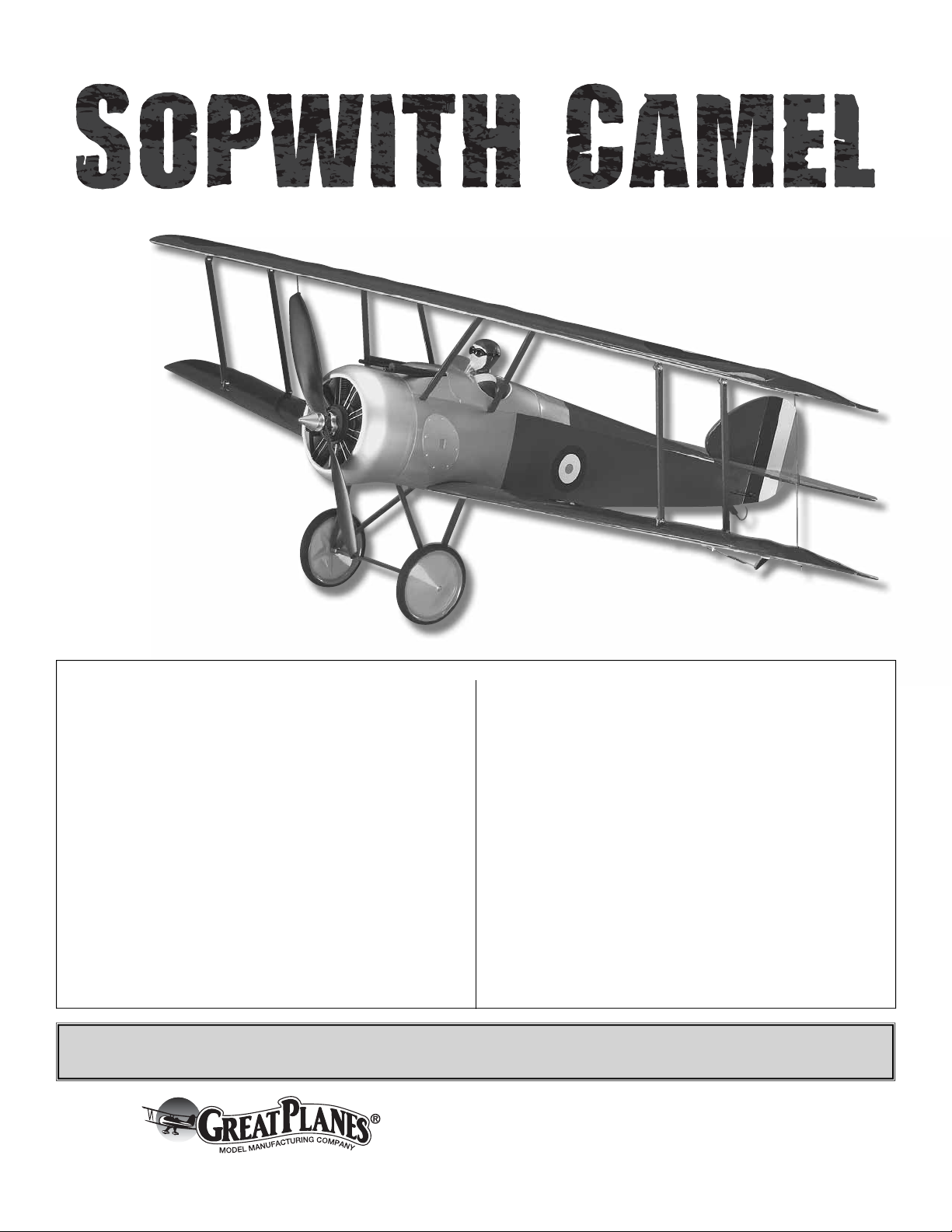
Wingspan: 35.5 in [900mm]
Wing Area: 389 in
Weight: 21.1 – 26.3 oz [595 – 745g]
Wing Loading: 7.8 – 9.7 oz/ft
Length: 25 in [630mm]
Radio: 4-channel, 4 micro servos
Motor: RimFire
ESC: ElectriFly
Battery: 11.1V (3S) 1250mAh – 1500mAh
2
[25.1dm2]
2
[24 – 30g/dm2]
™
400 (28-30-950) brushless
™
SS-25
WARRANTY
Great Planes® Model Manufacturing Co. guarantees this kit to be
free from defects in both material and workmanship at the date
of purchase. This warranty does not cover any component parts
damaged by use or modifi cation. In no case shall Great Planes’
liability exceed the original cost of the purchased kit. Further,
Great Planes reserves the right to change or modify this warranty
without notice.
In that Great Planes has no control over the fi nal assembly or
material used for fi nal assembly, no liability shall be assumed nor
accepted for any damage resulting from the use by the user of
the fi nal user-assembled product. By the act of using the userassembled product, the user accepts all resulting liability.
If the buyer is not prepared to accept the liability associated
with the use of this product, the buyer is advised to return
this kit immediately in new and unused condition to the place
of purchase.
To make a warranty claim send the defective part or item to Hobby
Services at the address below:
Hobby Services
3002 N. Apollo Dr., Suite 1
Champaign, IL 61822 USA
Include a letter stating your name, return shipping address, as
much contact information as possible (daytime telephone n umber,
fax number, e-mail address), a detailed description of the problem
and a photocopy of the purchase receipt. Upon receipt of the
package the problem will be evaluated as quickly as possible.
READ THROUGH THIS MANUAL BEFORE STARTING CONSTRUCTION. IT CONTAINS IMPORTANT
INSTRUCTIONS AND WARNINGS CONCERNING THE ASSEMBLY AND USE OF THIS MODEL.
Champaign, Illinois
(217) 398-8970, Ext 5
airsupport@greatplanes.com
Entire Contents © Copyright 2008 GPMA1144MNL V1.0
Page 2
TABLE OF CONTENTS
INTRODUCTION ......................................................................... 2
AMA ............................................................................................ 2
PRECAUTIONS ...........................................................................2
ADDITIONAL ITEMS REQUIRED .............................................. 3
Radio System ........................................................................ 3
Battery & Charger .................................................................. 3
Hardware & Accessories ....................................................... 3
Adhesives & Building Supplies .............................................. 4
Optional Supplies & Tools ...................................................... 4
BUILDING NOTES ......................................................................4
ORDERING REPLACEMENT PARTS ........................................ 4
KIT INSPECTION ........................................................................ 5
KIT CONTENTS .......................................................................... 5
METRIC/INCH RULER ................................................................ 5
ASSEMBLY ................................................................................. 6
Tighten the Covering ............................................................. 6
Mount the Horizontal & Vertical Stabilizers ............................ 6
Hook Up the Elevator & Rudder ............................................ 8
Mount the ESC & Receiver .................................................... 9
Mount the Motor ....................................................................9
Install the Replica Engine .................................................... 10
Install the Battery Plate ....................................................... 12
Mount the Aileron Servos .................................................... 13
Hook up the Bottom Ailerons ............................................... 14
Mount the Wings to the Fuselage ........................................ 15
Mount the Landing Gear ...................................................... 16
Connect the Top & Bottom Ailerons ..................................... 17
GET THE MODEL READY TO FLY ........................................... 18
Set the Control Throws ........................................................ 18
Balance the Propeller & Mount the Spinner ........................19
Balance the Model (C.G.) .................................................... 19
Balance the Model Laterally ................................................ 20
PREFLIGHT .............................................................................. 20
Identify Your Model .............................................................. 20
Charge the Batteries............................................................ 20
Range Check ....................................................................... 20
ELECTRIC MOTOR SAFETY PRECAUTIONS ........................ 20
AMA SAFETY CODE (excerpts) .............................................. 21
CHECK LIST ............................................................................. 21
FLYING ...................................................................................... 22
Prefl ight ............................................................................... 22
Takeoff ................................................................................. 22
Flight .................................................................................... 22
Landing ................................................................................ 22
For the latest technical updates or manual corrections to this
model visit the Great Planes web site at www.greatplanes.
com. Open the “R/C AIRPLANES” pull down tab across the
top of the page, then select “ARFs-ELECTRIC.” Scroll down
the page and click on “EP Sopwith Camel ARF.” If there is
new technical information or changes, an “Important! TECH
NOTICE” bo x will appear in the upper left corner of the page.
Click on the Tech Notice box to read the info.
AMA
We urge you to join the AMA (Academy of Model Aeronautics)
and a local R/C club. The AMA is the gov erning body of model
aviation and membership is required to fl y at AMA clubs.
Though joining the AMA provides many benefi ts, one of the
primary reasons to join is liability protection. Coverage is not
limited to fl ying at contests or on the club fi eld. It even applies
to fl ying at public demonstrations and air shows. Failure to
comply with the Safety Code (excerpts printed in the back of
the manual) may endanger insurance coverage. Additionally,
training programs and instructors are available at AMA club
sites to help you get started the right way. There are over
2,500 AMA chartered clubs across the countr y. Contact the
AMA at the address or toll-free phone number below:
Academy of Model Aeronautics
5151 East Memorial Drive
Muncie, IN 47302-9252
Tele. (800) 435-9262
Fax (765) 741-0057
Or via the Internet at:
http://www.modelaircraft.org
IMPORTANT!!! Two of the most important things you can do
to preserve the radio controlled aircraft hobby are to avoid
fl ying near full-scale aircraft and avoid fl ying near or over
groups of people.
INTRODUCTION
Thank you for purchasing the Great Planes EP Sopwith
Camel ARF. During our testing and development we were
pleasantly surprised to lear n how well this plane handles in
conditions normally too breezy for lightweight models of this
type–fl ying in 7 to 10 mph winds was no problem! Although
this WWI “bipe” doesn’t have the self-correcting tendencies
of a primary trainer, it is an “honest” fl yer that won’t reach
out and “bite” you. And it’s a model that appeals to just about
everybody–experienced pilots will chuckle while putting the
EP Sopwith Camel ARF through its aerobatic paces and
intermediate pilots will simply enjoy fl ying the EP Sopwith
Camel ARF on a calm evening, watching it fl y straight down
the runway.
PROTECT YOUR MODEL, Y OURSELF
& OTHERS....FOLLOW THESE
IMPORTANT SAFETY PRECAUTIONS
1. Your EP Sopwith Camel ARF should not be considered
a toy, but rather a sophisticated, working model that
functions very much like a full-size airplane. Because of its
performance capabilities, the EP Sopwith Camel ARF, if not
assembled and operated correctly, could possibly cause
injury to yourself or spectators and damage to property.
2. Y ou must assemble the model accor ding to the instructions.
Do not alter or modify the model, as doing so may result in an
unsafe or unfl yable model. In a few cases the instructions may
differ slightly from the photos. In those instances the wr itten
instructions should be considered as correct.
3. You must take time to build straight, true and strong.
2
Page 3

4. You must use an R/C radio system that is in fi rst-class
condition.
5. You must correctly install all R/C and other components
so that the model operates correctly on the ground and in
the air.
6. You must check the operation of the model before every
fl ight to insure that all equipment is operating and that the
model has remained structurally sound. Be sure to check
pushrod connectors often and replace them if they show any
signs of wear or fatigue.
7. If you are not an experienced pilot or have not fl own
this type of model before, we recommend that you get the
assistance of an experienced pilot in your R/C club for
your fi rst fl ights. If you’re not a member of a club, your local
hobby shop has information about clubs in your area whose
membership includes experienced pilots.
8. While this kit has been fl ight tested to exceed normal use,
if the plane will be used for extremely high-stress fl ying, such
as racing, or if a motor larger than the one recommended
will be used, the modeler is responsible for taking steps to
reinforce the high-stress points and/or substituting hardware
more suitable for the increased stress.
We, as the kit manuf acturer, provide you with a top quality ,
thoroughly tested kit and instructions, but ultimately the
quality and fl yability of your fi nished model depends
on how you build it; therefore, we cannot in any way
guarantee the performance of your completed model,
and no representations are expressed or implied as to the
performance or safety of your completed model.
Remember: Take your time and follow the instructions to
end up with a well-built model that is straight and true.
❏ Futaba S3114 micro servo – FUTM0414
❏ Futaba R114F 4-channel mini receiver – FUTL0442 low
band or FUTL0443 high band
❏ Matching Rx crystal – FUTL62** low band or FUTL63**
high band
The following servo extensions are also shown in
this manual:
❏ (2) AEC-26 300mm J-series aileron extension for the
aileron servos (FUTM4507)
❏ (1) AEC 13 J-series dual servo extension cord to connect
aileron servos to receiver (FUTM4130)
Battery & Charger
The EP Sopwith Camel ARF was designed for the Great
Planes ElectriFly™ 1250mAh or 1500mAh BP series LiPo
battery. The 1500 will provide slightly longer fl ight time, but
may cost a little more. Most importantly, read and follow
all the instructions and precautions that come with LiPo
batteries and chargers. Charge LiPo batteries only with
chargers intended for LiPo batteries or with chargers that
have a LiP o setting. F ollowing are the batteries and chargers
recommended for the EP Sopwith Camel ARF:
❏ Great Planes ElectriFly 11.1V 1250mAh 15C BP LiPo
battery w/Balance Connector (GPMP0713)
-or-
❏ Great Planes ElectriFly 11.1V 1500mAh 15C BP LiPo
battery w/Balance Connector (GPMP0717)
❏ Great Planes PolyCharge4
charger (GPMM3015)
Additionally, one (1) Great Planes Electr iFly Equinox™ LiPo
Cell Balancer w/3S battery adapter for each battery to be
charged simultaneously is recommended (GPMM3160).
™
DC-only LiPo battery
ADDITIONAL ITEMS REQUIRED
Radio System
The EP Sopwith Camel ARF requires a four-channel radio
with four micro servos and a mini receiver. The most basic
system would be something such as a Futaba® 4YF 4-channel
FM radio (FUTJ36**) with R114F mini receiver and two (2)
S3114 micro servos. Two more micro servos would need to
be purchased separately (FUTM0414). While this system is
suitable, a slightly more advanced system with dual rates
and endpoint adjustments would ease set up and maximize
fl ight performance. For modelers who already have an
advanced radio, but still must purchase a mini receiver and
micro servos separately, following are the recommended
part numbers for the radio gear shown in this manual:
Finally, if charging the battery from a 120V AC outlet is
preferred, a 12 volt power supply will also be required
(Hobbico® 12 Volt Power Supply – HCAP0250).
Hardware & Accessories
Following is the list of additional hardware and accessories
required to fi nish the EP Sopwith Camel ARF . Order numbers
are provided in parentheses.
❏ ElectriFly
brushless motor w/propeller adapter (GPMG4560)
™
RimFire™ 400 (28-30-950kV) out-runner
❏ ElectriFly Silver Series 25 Amp Brushless
ESC (GPMM1820)
❏ (1 pkg. of 3) Great Planes 3.5mm male/2mm female
bullet adapters (GPMM3122)
❏ Great Planes 10 x 4.5 Power Flow Slo-Flyer Elec Prop
(pkg. of 2) (GPMQ6660)
❏ (1 pkg) Great Planes adhesive-back Velcro
3
®
(GPMQ4480)
Page 4

❏ 1/2" [13mm] double-sided foam mounting
tape (GPMQ4440)
❏ Stick-on segmented lead weights (GPMQ4485)
Adhesives & Building Supplies
In addition to common household tools and hobby tools, this
is the “short list” of the most important items required to build
the EP Sopwith Camel ARF. Great Planes Pro™ CA glue is
recommended.
❏ 1/2 oz. [15g] Thin Pro CA (GPMR6001)
❏ 1/2 oz. [15g] Medium Pro CA+ (GPMR6007)
❏ CA applicator tips (HCAR3780)
❏ Threadlock er threadlocking cement (GPMR6060)
❏ #11 blades (5-pac k, HCAR0211)
❏ #1 Hobby knife (HCAR0105)
Optional Supplies & Tools
ORDERING REPLACEMENT PARTS
Replacement parts for the Great Planes EP Sopwith
Camel ARF are available using the order numbers in the
Replacement Parts List that follows. The fastest, most
economical service can be provided by your hobby dealer or
mail-order company.
To locate a hobby dealer, visit the Hobbico web site at
www.hobbico.com. Choose “Where to Buy” at the
bottom of the menu on the left side of the page. Follow the
instructions provided on the page to locate a U.S., Canadian
or International dealer.
Parts may also be ordered directly from Hobby Services by
calling (217) 398-0007, or via facsimile at (217) 398-7721,
but full retail prices and shipping and handling charges will
apply. Illinois and Nevada residents will also be charged
sales tax. If ordering via fax, include a Visa
number and expiration date for payment.
®
or MasterCard®
Here is a list of optional tools mentioned in the manual that
will help you build the EP Sopwith Camel ARF.
❏ 2 oz. [57g] spray CA activ ator (GPMR6035)
❏ 4 oz. [113g] aerosol CA activator (GPMR6034)
❏ R/C-56 canopy glue (JOZR5007)
❏ CA debonder (GPMR6039)
❏ Medium T-pins (100, HCAR5150)
❏ Metal Template Set (30/60/90 and 45° triangles, HCAR0500)
❏ Hobby Heat
❏ C.G. Machine
A model airplane covering iron with a protective covering sock
may also be necessary to retighten the covering and remove
any wrinkles that may have formed after the model was
originally covered at the factory. If you don’t already have a
covering iron, the 21st Century® sealing iron (COVR2700) and
21st Century iron cover (COVR2702) are recommended.
• The stabilizer and wing incidences and motor thrust
angles have been factory-built into this model. However,
some technically-minded modelers may wish to check these
measurements anyway. To view this information visit the web
site at www.greatplanes.com and click on “Technical Data. ”
Due to manufacturing tolerances which will have little or no
effect on the way your model will fl y, please expect slight
deviations between your model and the published values.
™
micro torch (HCAR0755)
™
(GPMR2400)
BUILDING NOTES
Mail parts orders and payments by personal check to:
Hobby Services
3002 N. Apollo Drive, Suite 1
Champaign, IL 61822
Be certain to specify the order number exactly as listed in
the Replacement Parts List. Payment by credit card or
personal check only; no C.O.D.
If additional assistance is required for any reason contact Product
Support by e-mail at productsupport@greatplanes.com, or
by telephone at (217) 398-8970.
Replacement Parts List
Description How to Purchase
Missing pieces Contact Product Support
Instruction manual Contact Product Support
Full-size plans Not available
Contact your hobby supplier for the following parts:
GPMA3110 Top Wing
GPMA3111 Bottom Wing
GPMA3112 Fuselage
GPMA3113 Tail Set
GPMA3114 Cowl
GPMA3115 Dummy Engine
GPMA3116 Landing Gear
GPMA3117 Cabanes
GPMA3118 Spinner
GPMA3119 Gun Set
GPMA3120 Strut Set
GPMA3121 Battery Hatch
GPMA3122 Decal
4
Page 5
KIT INSPECTION
KIT INSPECTION
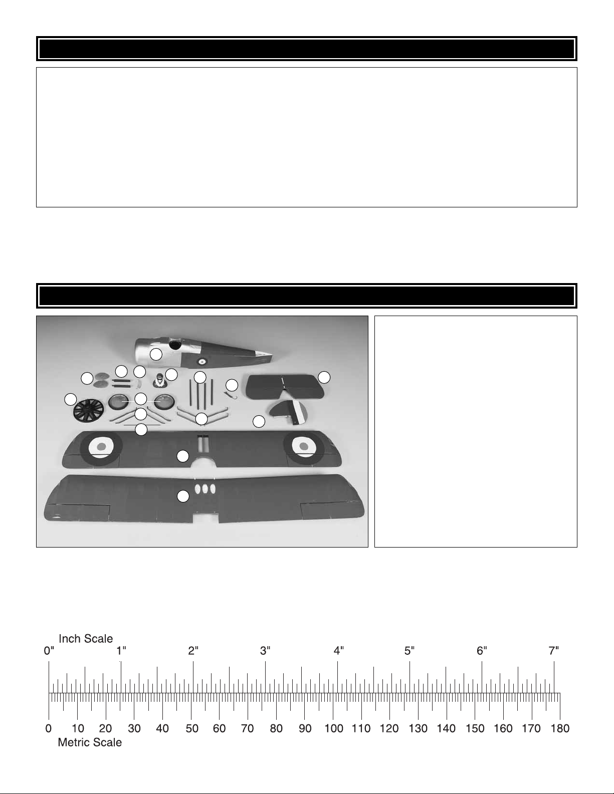
KIT CONTENTS
Before starting to build, take an inventory of this kit to make sure it is complete and inspect the parts to make sure they
are of acceptable quality. If any parts are missing or are not of acceptable quality, or if you need assistance with assembly,
contact Product Support. When reporting defective or missing parts, use the part names exactly as they are written in
the Kit Contents list.
Great Planes Product Support:
3002 N Apollo Drive, Suite 1
Champaign, IL 61822
Telephone: (217) 398-8970, ext. 5
Fax: (217) 398-7721
E-mail: airsupport@greatplanes.com
KIT CONTENTS
Kit Contents
1
3
2
6
4
7
8
9
5
10
11
12
14
13
1 Fuselage
2 Inspection Panels (L&R)
3 Machine Guns
4 Windscreen
5 Pilot
6 Replica Engine
7 Main Wheels (2)
8 Landing Gear Struts (4)
9 Cross Tube
15
10 Wing Struts (4)
11 Cabane Struts (4)
12 Tail Skid
16
13 Horizontal Stabilizer w/Elevators
14 Vertical Stabilizer & Rudder
15 Top Wing w/Ailerons
16 Bottom Wing w/Ailerons
To convert inches to millimeters, multiply inches by 25.4
5
5
Page 6
ASSEMBLY
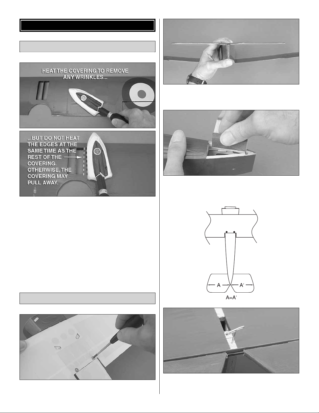
Tighten the Covering
❏ 2. Holding the horizontal stabilizer (stab) on the fuselage,
view the model from the rear to see if it is parallel with
the wing.
❏ 1. Use a covering iron set to approximately 250 to 300
degrees F [120 to 150 degrees C] with a protective covering
sock to remove any wrinkles and tighten the covering
wherever it looks loose . Be careful along edges and seams–
if an edge or seam is heated at the same time as the rest of
the covering, it may pull away when it shrinks.
Note: If too much heat is used, delicate parts like the wings
and tail may twist or warp. These parts can be straightened
by carefully twisting them in the opposite direction, then
re-shrinking the covering on the top and bottom.
Mount the Horizontal & Vertical Stabilizers
❏ 3. If necessary, use a small sanding block with medium-
grit sandpaper to carefully sand the “high side” of the stab
saddle so the stab will be parallel with the wing.
❏ 1. Temporarily mount the bottom wing to the fuselage
with two 3 x 20mm screws and 3mm washers.
❏ 4. Taking accurate measurements, center the TE of the
stab from side-to-side over the end of the fuselage and hold
it in place with a pin.
66
6
Page 7
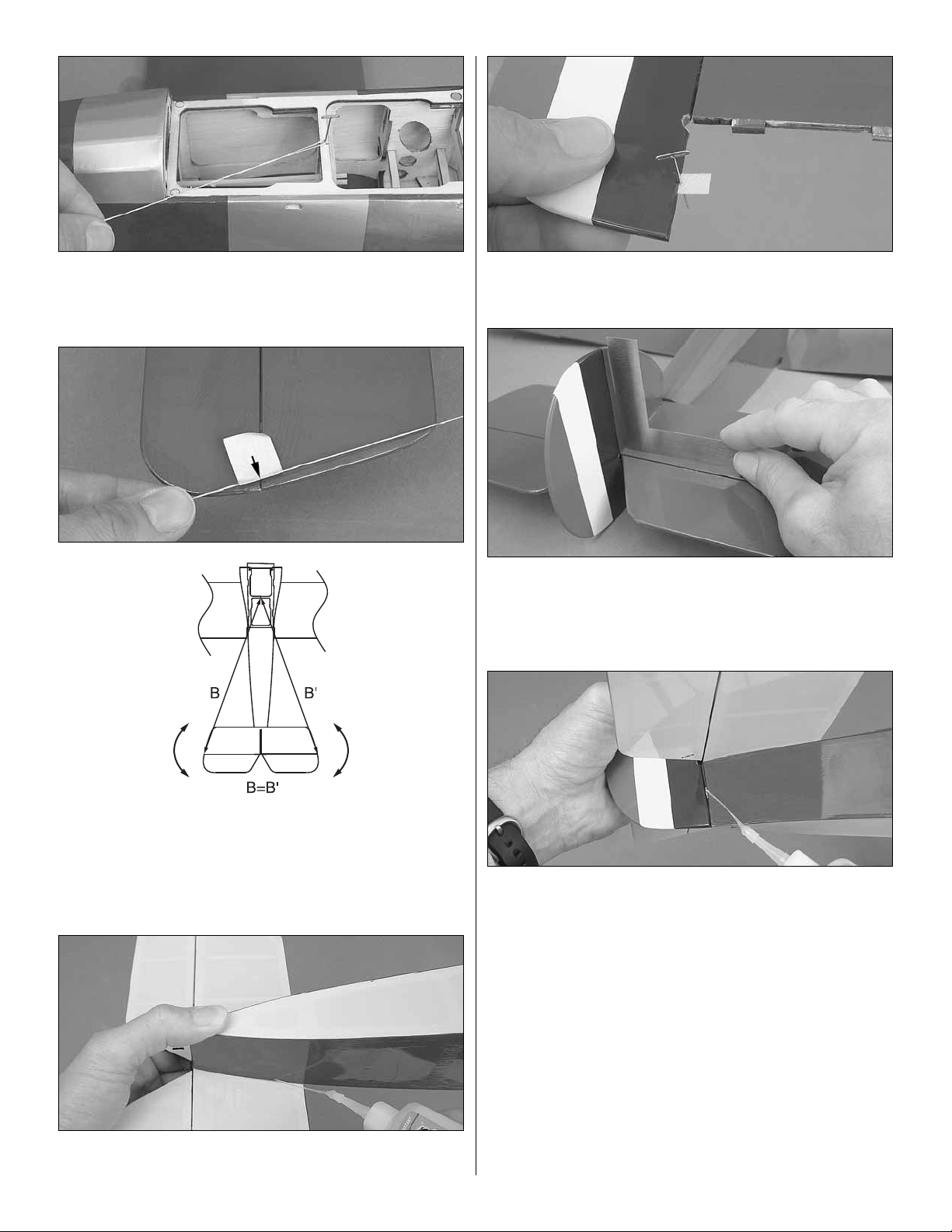
❏ 5. Stick another T-pin through the cockpit base at the
centerline. Tie a loop in one end of an approximately 24"
[600mm] piece of non-elastic string such as Kevlar® fi shing
thread or something similar. Fit the loop over the T-pin.
❏ 8. Insert a pin through the middle of the 1/4" x 1/2"
[6 x 13mm] CA hinge–the pin will keep the hinge centered.
Insert the hinge into the bottom of the rudder.
❏ 9. Join the vertical stabilizer (fi n) to the stab and fi t the
hinge into the slot in the back of the fuselage. Use medium
CA to glue the fi n to the top of the stab. While the CA is
hardening, use a small builder’s square to make sure the fi n
is perpendicular.
❏ 6. Wrap a piece of masking tape over the string near the
other end and mark an arrow on the tape. Slide the tape along
the string until the arrow aligns with one end of the stab. Swing
the string over to the other end of the stab to see if the distances
are equal as shown in the sketch. Rotate the stab on the pin
and slide the tape along the string until the stab is aligned.
❏ 7. Holding the stab in position, use thin CA to securely
glue the stab to the fuselage.
❏ 10. Remove the pin from the CA hinge. Add two or three
drops of thin CA to each side of the hinge in the bottom of
the rudder and the fuselage
❏ 11. If you haven’t already done so you may remove the
bottom wing from the fuselage.
7
Page 8
Hook Up the Elevator & Rudder
❏ 1. Test fi t the “Z-bend” of one of the two longest wire
pushrods into the outer hole of one of the fi berglass control
horns as shown in the photo. If necessary, spin the horn
around the wire a few times to loosen the hole in the horn so
the pushrod will move freely.
or with your ESC and the motor battery, so you can operate
the servos with the transmitter. Center the trims on your
transmitter and turn on the transmitter and receiver . Position
the servo arm on each servo so the longer arms will be
perpendicular to the servos.
❏ 2. With the horn attached to the pushrod, slide the pushrod
into the rudder guide tube in the fuselage. Fit the horn into the
slot in the rudder. Use a few drops of thin CA followed by a few
drops of medium CA to securely glue the horn into position.
❏ 3. Connect the elevator pushrod the same way.
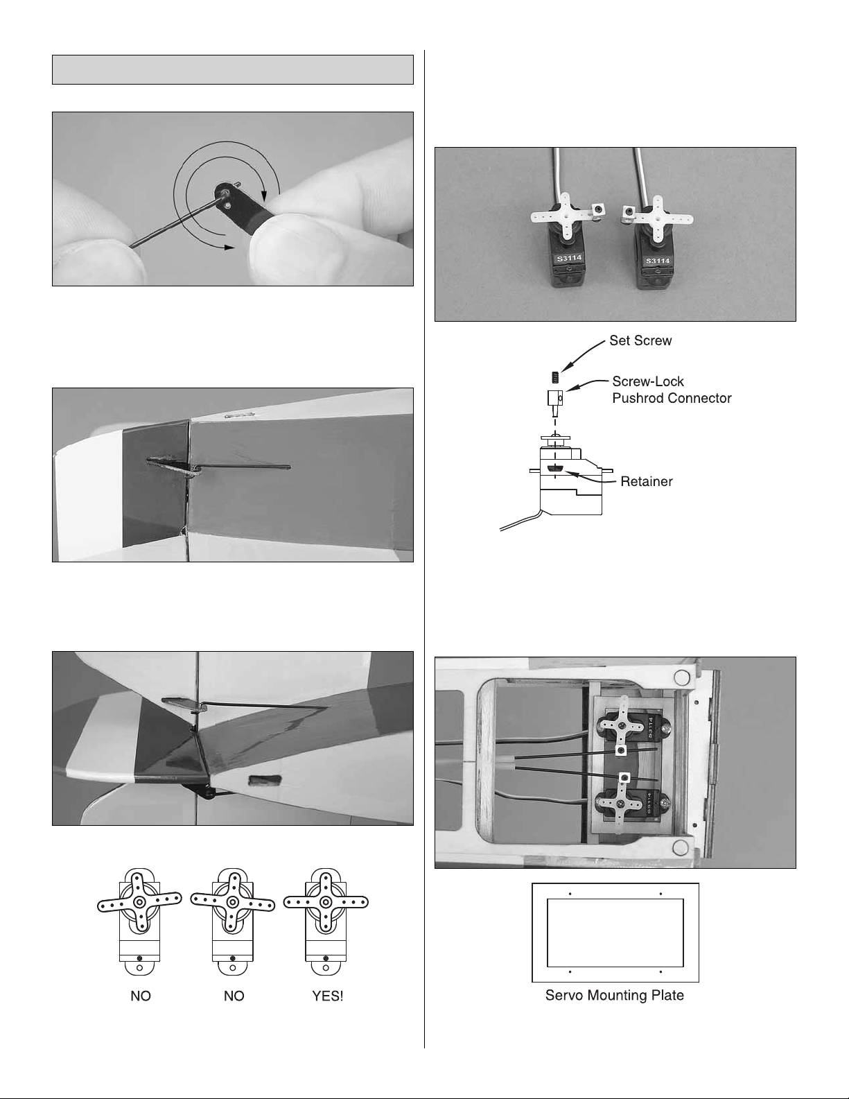
❏ 5. Use a #56 (.046" [1.2mm]) drill or a hobby knife to
enlarge the holes in the servo arms for the screw-lock pushrod
connectors. Mount the screw-loc k pushrod connectors to the
servo arms with the nylon retainers.
Refer to this photo for the next four steps.
❏ 4. Temporarily connect the servos you will be using for the
elevator and rudder to your receiver with a receiver battery,
❏ 6. T est fi t the elev ator and rudder servos in the servo rails
in the fuselage. If the rails are too f ar apart for the servos you
8
8
Page 9

are using, center the plywood servo mounting plate on the
rails and glue it into position. Then, place the servos on the
mounting plate.
❏ 7. Fit the pushrods through the screw-loc k pushrod connectors
on the servo arms. If necessary, shor ten the pushrods by
cutting them.
❏ 8. For small models such as this it has become common
practice to glue the servos into position. If this is your
preference use medium CA to securely glue the servos to
the rails. However, if you prefer to mount your servos the
conventional way with screws, use the 2 x 6mm Phillips
screws included with this kit – you should be able to simply
tighten them into the wood – no drilling is necessary.
❏ 9. Re-connect the servos to your receiver and turn the
system on. Center the ele vator and rudder and lock the
pushrods to the screw-lock pushrod connectors by tightening
the set screws with a small drop of threadlocker and the small
hex wrench that came with this model. Secure the servo arms
to the servos with the screws that came with the servos.
❏ 2. Position the ESC/receiver mounting plate so it will be
1" [25mm] from the bottom of the former as shown. Use
medium CA to glue the mounting plate into position.
Mount the ESC & Receiver
❏ 3. Use double-sided foam mounting tape (not included) to
mount the ESC and receiver to the top of the mounting plate
as shown.
❏ 4. Guide the receiver antenna down and out through the
antenna tube in the fuselage.
Mount the Motor
❏ 1. Fit, but do not glue the plywood ESC/receiver
mounting plate where shown in the fuselage–it may take
a bit of “wriggling” to get it into position, but rest assured the
plate will fi t.
❏ 1. Remo ve the metal motor mount that came on the motor .
Mount the fi berglass motor mount included with this kit to
the motor with the screws and a drop of threadlocker on the
threads. Also connect the 3.5mm male/2.0mm female bullet
wire adapters (not included–GPMM3122) to the motor wires.
9
Page 10

❏ 2. Mount the motor mount to the fi rewall on the fuselage
with three 3 x 20mm Phillips screws (apply a drop of
threadlocker to the threads), a 1/2" [13mm] tube and a 3mm
washer on each screw behind the motor mount.
❏ 3. Connect the motor wires to the wires coming from the
ESC. Turn on the transmitter and connect a motor battery to
the ESC. Adv ance the throttle stick to mak e sure the motor is
turning the correct direction. If the motor is turning backwards,
switch any two wires connecting the ESC and motor to get
the motor to turn in the correct direction (counterclockwise
when viewed from the front).
Install the Replica Engine
❏ 2. Use a pin vise with a small drill or a hobby knife to
drill the holes for the pushrod wires. The size of the drill
isn’t critical–it just has to be approximately the same size or
slightly larger than the pushrod wires so they will fi t into the
holes. The pushrod wires are .040" [1mm] dia., so a #60 drill
(.040" [1mm] or slightly larger) is suitable.
❏ 3. Once all the holes are drilled, install the pushrod wires.
Glue the wires into position from the back of the replica
engine with medium CA.
❏ 4. As best as you can, position the replica engine into the
cowl as described below:
❏ 1. Use plastic-cutting scissors or a hobb y knife to cut a way
part of the “ring” around the replica engine as shown.
❏ A. Straddle the bottom two engine cylinders over the
balsa cowl ring as shown.
10
Page 11

❏ B. Turn it into position.
❏ 5. Center the bottom cylinder in the opening in the bottom
of the cowl.
❏ 8. While we’re working on the front of the fuselage, it will
be easier to glue on the inspection panels now before the
wings are mounted. Add six or eight small drops of medium
CA to the back of each panel, and then glue them into
position on the sides of the fuselage where shown.
❏ 6. Center the replica engine in the cowl and push it all
the way forward. View it from all angles to make sure it is
centered. Then, glue it into position with thin CA.
❏ 7. Use a hobby knife or a rotary tool with a drum sander
to enlarge the opening in the replica engine until it fi ts over
the motor.
❏ 9. Test fi t the cockpit hatch. If necessary, use a hobby
knife to carefully trim back the balsa former at the bottom
front of the hatch so it will clear the back of the cowl during
installation and removal.
11
Page 12

❏ 10. While holding the windscreen in position, add a small
drop of CA to one spot and apply a drop of CA accelerator
with a T-pin or a small piece of wire.
Install the Battery Plate
❏ 1. Test fi t the plywood battery plate into the fuselage
and apply a strip of adhesive-back Velcro (GPMQ4480, not
included) to the top as shown.
❏ 3. Apply the opposite side of Velcro to your battery–note
that the Velcro strip on the battery is only about 3/8" [10mm]
wide. It takes only a small amount of V elcro to keep the battery
from shifting and if you use too much Velcro the battery will
be too diffi cult to take out.
❏ 4. Mount the battery plate in the fuselage with two #2 x 3/8"
[10mm] fl at head screws. Mount the battery to the plate.
❏ 2. Make a battery strap from the hook & loop strips
included with this kit. Use medium CA to glue the str ap to the
bottom of the battery plate.
❏ 5. T est fi t the cockpit hatch to the fuselage to make sure it
fi ts over the battery. Make any adjustments necessary.
Hint: When you get to the fl ying fi eld and are in the process
of disconnecting the battery , it will be helpful to have a piece
12
Page 13

of wire with a “hook” on the end to “fi sh out” the battery wires.
Otherwise, getting to the wires to disconnect the battery may
be diffi cult when the wings and cabanes are in the way.
Mount the Aileron Servos
❏ 1. Same as was done with the elevator and rudder
servos, temporarily connect one of your aileron servos to
your receiver with a battery so you can power the system up .
Center the aileron trim on your transmitter, turn on the radio
and “square up” the servo arm.
❏ 2. Connect the other aileron servo to the receiver and
repeat the procedure. Cut off the unused arms as shown.
❏ 5. If you prefer to mount your servos with screws, place a
1/4" x 1/2" [7 x 12mm] servo mounting block on each side
of one of the aileron servos. Place pieces of thin cardstock
between the servo and the blocks and under the servo as
shown. Drill #60 (.040" [1mm]) holes through the blocks for
the servo mounting screws.
❏ 6. With the cardstock in position, mount the servo to the
blocks with two 2 x 6mm screws.
❏ 3. Use a #58 (.042" [1mm]) drill or a hobby knife to slightly
enlarge the holes in the servo arms so the 1-9/16" [40mm]
aileron pushrods will fi t. Test fi t the pushrods to make sure
they fi t easily.
If you prefer to mount your servos with screws rather
than gluing them in, skip this step…
❏ 4. Clean the sides of the aileron servos with denatured
alcohol, then use medium CA to glue them to the hatches
with the output arms centered in the openings as shown in
the photo at step 7.
❏ 7. Apply medium CA to the bottom of each mounting b lock
and to the aileron hatch. Glue the blocks to the hatch with
the servo arm centered in the opening.
❏ 8. Temporarily remove the servo. Add a drop of thin CA
to the screw holes in the blocks and allow the CA to harden.
Remount the servo with the screws.
13
Page 14

❏ 9. Mount the other aileron servo to the other hatch the
same way. If you haven’t done so already, be sure to mount
the servo arms to the servos with the screws.
❏ 10. Connect an 8" to 12" [200 to 300mm] servo extension
wire to one of the aileron servos. (A Futaba 300mm J-series
extension w/slim lead was used in this model–FUTM4507.)
Tie the string coming from the aileron hatch to the connector
on the end of the servo wire. Pull the wire through and out
the hole in the middle of the wing.
Hook Up the Bottom Ailerons
❏ 1. Same as was done for the elevator and rudder horns
and pushrods, fi t one of the aileron pushrods into the outer
hole in one of the fi berglass control horns. Spin the horn
around the pushrod several times to wear the paint off the
wire and loosen the fi t in the hole.
Refer to this photo for the next two steps.
❏ 11. Mount the aileron hatch cover in the wing with four
#2 x 3/8" [10mm] fl at head Phillips screws.
❏ 12. Mount the other aileron servo hatch in the wing the
same way.
❏ 2. Fit the horn into the slot in the bottom of the right aileron.
Glue the horn into place with a few drops of thin CA follo wed
by a few drops of medium CA.
❏ 3. Fit a second aileron pushrod into the servo arm. The
pushrods should be parallel with each other. If they are not
parallel, remove the pushrod from the servo arm. Use long
nose pliers to bend the part of the pushrod that goes into the
servo arm so the pushrod will be parallel with the pushrod in
the aileron control horn as shown in the photo.
❏ 4. Temporar ily unscrew the aileron hatch from the wing
so you can slide a piece of the 1" [25mm] heat-shrink tubing
over both pushrods. Reinstall the hatch.
❏ 5. Hold the aileron centered to the wing with a small piece
of masking tape.
14
Page 15

❏ 6. Connect the aileron servo wire coming out the middle
of the wing to the receiver with a battery. Turn on the radio
so the servo will center. Working quickly, add a few drops of
medium CA to the pushrods where they overlap and center
the heat-shrink tubing over the pushrods. Use a solder ing
iron to shrink the tubing. Add a drop of thin CA to both ends
of the heat-shrink tubing where the wires come out. Remov e
the masking tape.
❏ 7. Connect the other servo to the other aileron the same w a y.
Mount the Wings to the Fuselage
❏ 3. T est fi t the four aileron pushrods into the f our fi berglass
aileron pushrod tabs. Rotate the tabs around the pushrods
to wear the paint off the pushrods and “break in” the holes.
❏ 4. Fit, then use thin CA to glue the tabs into the slots in
the TE of each aileron.
❏ 1. Cut all the plywood wing strut mounting tabs from the
“tree” they are attached to.
❏ 5. There are eight, painted aluminum struts included with
this kit (there are four others that are wood). Separate the
cabane struts (for mounting the top wing) from the landing
gear struts–the cabanes are the ones that don’t have any
holes in one end. Also separate the front cabane struts
from the rear cabane struts–the front cabane struts are the
ones that have the longer tabs (without holes) on the end.
❏ 2. Note that there are three different kinds of mounting
tabs–two with an inward angle, two with an outward angle and
four with a 90° angle. All the 90° mounting tabs go in the top
wing. Fit the tabs into the wings as shown in the illustration.
Then, securely glue them into position with thin CA.
❏ 6. Fit, but do not glue the rear cabanes into the fuselage–
the way to tell if the cabanes are installed correctly is how
they fi t. When installed correctly, the angle on the bottom will
be parallel with the fuselage side.
15
Page 16

❏ 7. Fit, b ut do not glue the front cabanes into the fuselage.
When installed correctly, the front cabanes should have a
slightly rearward sweep.
❏ 10. Use 2.6 x 8mm washer-head screws to mount the
front and rear wing struts to the mounting tabs–the front
struts are approximately 1/16" [1.6mm] shorter than the rear
struts and it doesn’t matter which end is up. Use care not to
overtighten the screws or they will strip out of the tabs. If you
do accidentally strip out one of the tabs, or if you would like
the screws to have a little more “bite,” remove the screws,
add a drop of thin CA to each hole, allow to harden, and then
remount the struts.
❏ 11. Once both wings are mounted, use thin CA to glue the
cabane struts into the fuselage.
The top and bottom ailerons are ready to be connected, but it
will be easier to do after the landing gear has been mounted
and the plane is sitting on its “legs.”
❏ 8. Turn the fuselage upside-down. Fit the cabanes into the
top wing and drill 1/16" [1.6mm] holes into the wing for the
mounting screws. Mount the cabanes to the wing with four
#2 x 3/8" [10mm] fl at-head Phillips screws. Note: If any of
the screws are too long and contact the covering on the top
wing, use wire cutters to cut 1/16" [1.6mm] from the end of
the screws.
❏ 9. Connect a dual servo extension or a Y-harness to the
aileron servo wires coming out the hole in the middle of the
bottom wing. Bolt the bottom wing to the fuselage with the
3 x 20mm screws and 3mm washers. From the top of the
fuselage down inside the cockpit hatch, connect the dual
servo extension to the aileron channel in your receiver.
Mount the Landing Gear
❏ 1. Mount the front and rear landing gear struts to the
bottom of the fuselage with six #2 x 3/8" [10mm] fl at-head
Phillips screws. Do not tighten the screws all the w ay y et. The
struts should be loose.
16
Page 17

❏ 2. Mount the wheels to the struts with a 3 x 25mm bolt and
two 3mm nuts. Use threadlocker and tighten the nuts to the
struts, but make sure the wheels can roll freely.
Connect the Top & Bottom Ailerons
❏ 1. Hold each top aileron centered to the wing with small
pieces of masking tape. If you have mounted the propeller,
remove it. Connect the motor battery to the ESC and turn on
the transmitter.
❏ 2. Fit one aileron pushrod into the tab in the top aileron
and another aileron pushrod into the tab in the bottom aileron
on one side of the wing.
❏ 3. Fit the cross tube between the wheels by inserting the
ends of the 3mm bolts into each end. Tighten the screws in
the struts to the wing and fuselage.
❏ 3. Slip a piece of heat-shrink tubing over the bottom
pushrod. Apply a few drops of medium CA to the pushrods
where they contact each other. Slide the heat-shrink tubing
equally over both pushrods. Working quickly, use a soldering
iron or a hobby torch to shrink the tubing.
❏ 4. Apply a drop of thin CA to the pushrod wires where they
come out both ends of the heat-shrink tubing.
❏ 5. Connect the pushrods to the other aileron the same
way. Remov e the masking tape and operate the ailerons with
the transmitter to make sure everything operates smoothly.
❏ 4. Test fi t the tail skid into the bottom of the fuselage. Note
how the notch in the end of the skid should catch another
notch in a plywood plate inside the fuselage. Once you see
how the skid fi ts, remove the skid and glue it into position
with medium CA.
17
Page 18

GET THE MODEL READY TO FLY
Set the Control Throws
❏ 1. If using a device that measures model airplane control
throws in degrees, follow the instructions that came with
the device to measure and set the throws according to the
measurements provided on page 19. If measuring the throws
with a ruler, proceed with the following instructions.
❏ 4. Use the transmitter to move the elevator up. Move the
ruler forward so it will still be touching the TE. The distance
the elevator mo v es is the “up ele v ator” control thro w. Use the
endpoint adjustment in your transmitter or move the screwlock pushrod connector in the elevator servo arm to a new
hole to change the throw according to the measurements
provided below.
❏ 5. Measure and set the up and down and left and right
control throws for all of the control surfaces. If your radio
does not have dual rates, we recommend setting the throws
at the high rate setting. Note: The rudder throw is measured
at the widest part of the rudder.
❏ 2. Set the throws on the elevator fi rst. Use a small box or
something similar to prop up the bottom of the fuselage until
the wings and horizontal stabilizer are level.
❏ 3. With the transmitter and receiver on and the elevator
centered, hold a ruler up to the TE of the elevator.
These are the recommended control surface throws:
HIGH RATE
ELEVATOR: 1/2" [13mm], 15° up
1/2" [13mm], 15° down
RUDDER: 1" [25mm], 22° up
1" [25mm], 22° down
AILERONS: 5/8" [16mm], 19° up
5/8" [16mm], 19° down
LOW RATE
ELEVATOR: 5/16" [8mm], 10° up
5/16" [8mm], 10° down
RUDDER: 1-1/4" [32mm], 17° up
1-1/4" [32mm], 17° down
AILERONS: 3/8" [10mm], 16° up
3/8" [10mm], 16° down
IMPORTANT: The Great Planes EP Sopwith Camel ARF
has been extensively fl own and tested to arrive at the throws
at which it fl ies best. Flying your model at these throws will
provide you with the greatest chance for successful fi rst
fl ights. If, after you have become accustomed to the way
the EP Sopwith Camel ARF fl ies, you would like to change
the throws to suit your taste, that is fi ne. Ho we v er, too much
control throw could make the model diffi cult to control, so
remember, “more is not always better.”
18
Page 19

Balance the Propeller & Mount the Spinner
❏ 1. F or optimum performance and motor effi ciency balance
the propeller using a Top Flite® Precision Magnetic Prop
Balancer (TOPQ5700) or other suitable balancer. Use a
hobby knife or sandpaper to sand the heavy blade until you
can get the prop to balance.
❏ 1. If using a Great Planes C.G. Machine to balance your
EP Sopwith Camel ARF, set the rulers to 2-7/8" [73mm]. If
not using a C.G. Machine, use a fi ne-point felt-tip pen to draw
short lines marking the balance point on the bottom of the
top wing 2-7/8" [73mm] from the LE as shown. Place 1/16"
[1.5mm] strips of tape over the marks so you will be able to
feel the balance point with your fi ngers when you turn the
model upside-down.
This is where your model should balance for the fi rst fl ights.
Later, y ou may wish to experiment by shifting the C .G. up to
1/4" [6mm] forward or 1/4" [6mm] back to change the fl ying
characteristics. Moving the C.G. forward may improve the
smoothness and stability, but the model may then require
more speed for takeoff and make it more diffi cult to slow
for landing. Moving the C.G. aft makes the model more
maneuverable, but could also cause it to become too
diffi cult to control. In an y case, start at the recommended
balance point and do not at any time balance the model
outside the specifi ed range.
❏ 2. Mount the propeller with the propeller washer and
propeller nut. Tighten the nut with an 8mm or 5/16" wrench.
Install the aluminum propeller cone and tighten with a piece
of wire through the hole in the front.
Balance the Model (C.G.)
More than any other factor, the C.G. (balance point) can
have the greatest effect on how a model fl ies, and may
determine whether or not your fi rst fl ight will be successful.
If you value this model and wish to enjo y it for man y fl ights,
DO NOT OVERLOOK THIS IMPORTANT PROCEDURE.
A model that is not properly balanced will be unstable and
possibly unfl yable.
At this stage the model should be completely ready-to-fl y
with all of the systems in place including the motor, propeller ,
motor battery, ESC, and the complete radio system.
❏ 2. Place the model on your C.G. Machine or lift it with y our
fi nger tips at the balance point you marked on the bottom
19
Page 20

of the top wings. When the model is balanced correctly the
wings and horizontal stabilizer will be level (the model in the
photo is very slightly tail-heavy). If the tail is low the model
is “tail heavy” and weight must be added to the nose. If the
nose is low the model is “nose heavy” and weight must be
added to the tail. Carefully lay segments of Great Planes
“stick-on” lead (GPMQ4485) on the tail or nose until y ou can
get the model to sit level. Once you know how much weight
is required, attach it to the model. T ail w eight can be stuc k to
the fuselage under the horizontal stabilizer and nose weight
can be stuck to the fi rewall next to the motor–it is likely that
1/2 to 1 oz. [15 to 30 g r ams] will be needed on the fi rewall to
get the model to balance.
CAUTION: Unless the instructions that came with your
radio system state differently, the initial charge on new
transmitter and receiver batteries should be done for 15
hours using the slow-charger that came with the radio
system. This will “condition” the batteries so that the next
charge may be done using the fast-charger of y our choice .
If the initial charge is done with a fast-charger the batteries
may not reach their full capacity and you ma y be fl ying with
batteries that are only partially charged.
Range Check
❏ 3. IMPORTANT: If you found it necessary to add any weight,
recheck the C.G. after the weight has been installed.
Balance the Model Laterally
❏ 1. Lift the model by the tail skid and the propeller shaft
several times and note which wing tip drops.
❏ 2. If one wing always drops, it means that side is heavy.
Balance the airplane by adding weight to the bottom of the
opposite wing near the tip. An airplane that has been laterally
balanced will track better in loops and other maneuvers.
PREFLIGHT
When you get to your fl ying site ground check the
operational range of the radio before the fi rst fl ight of the
day. With the transmitter antenna collapsed and the receiver
and transmitter on, you should be able to walk at least
100 feet away from the model and still have control. Have
an assistant stand by your model and, while you work the
controls, tell you what the control surfaces are doing. Repeat
this test with the motor running at various speeds with an
assistant holding the model, using hand signals to show you
what is happening. If the control surfaces do not respond
correctly, do not fl y! Find and correct the problem fi rst. Look
for loose servo or battery connections, damaged wires or a
damaged receiver crystal from a previous crash in another
model. One other possible source of radio “noise” that could
cause interference is the arrangement and relative location
of the receiver , receiver antenna and motor wires. If possible,
remount the receiver in a different location or re-route some
of the wires. Then, try the range check again.
ELECTRIC MOTOR SAFETY PRECAUTIONS
Failure to follow these safety precautions may result
in severe injury to yourself and others.
Identify Y our Model
No matter if you fl y at an AMA sanctioned R/C club site or
if you fl y somewhere on your own, you should always have
your name, address, telephone number and AMA number
on or inside your model. It is required at all AMA R/C club
fl ying sites and AMA sanctioned fl ying events. Use a fi nepoint felt-tip pen to write the information somewhere inside
the airplane such as on the bottom of the cockpit.
Charge the Batteries
Follow the battery charging instructions that came with your radio
control system to charge the transmitter batteries. You should
always charge your transmitter the night before you go fl ying,
and at other times as recommended by the radio manuf acturer .
Use safety glasses when running the motor.
Do not run the motor in an area of loose gravel or sand; the
propeller may throw such material in your face or eyes.
Keep your f ace and body as w ell as all spectators a wa y from
the plane of rotation of the propeller as it is turning.
Keep these items away from the prop: loose clothing, shirt
sleeves, ties, scarfs, long hair or loose objects such as
pencils or screwdrivers that may fall out of shirt or jacket
pockets into the prop.
Always remov e the LiPo battery from the plane before charging.
Always use a charger designed to charge LiPo batter ies for
charging the LiPo fl ight battery.
Never leave the LiPo battery unattended while charging. If
the battery becomes hot, discontinue charging.
20
Page 21

AMA SAFETY CODE (excerpts)
Read and abide by the following excerpts from the Academy
of Model Aeronautics Safety Code. For the complete Safety
Code refer to Model A viation magazine, the AMA web site or
the Code that came with your AMA license.
9) Under no circumstances may a pilot or other person
touch a powered model in fl ight; nor should any part of the
model other than the landing gear, intentionally touch
the ground, except while landing.
CHECK LIST
General
1) I will not fl y my model aircraft in sanctioned events , air shows,
or model fl ying demonstrations until it has been proven to be
airworthy by having been pre viously, successfully fl ight tested.
2) I will not fl y my model aircraft higher than approximately
400 feet within 3 miles of an airport without notifying the
airport operator . I will giv e right-of-wa y and av oid fl ying in the
proximity of full-scale aircraft. Where necessary , an observer
shall be utilized to supervise fl ying to avoid having models fl y
in the proximity of full-scale aircraft.
3) Where established, I will abide by the safety rules for the
fl ying site I use, and I will not willfully and deliberately fl y my
models in a careless, reckless and/or dangerous manner.
5) I will not fl y my model unless it is identifi ed with my name
and address or AMA number, on or in the model. Note: This
does not apply to models while being fl own indoors.
7) I will not operate models with pyrotechnics (any device
that explodes, burns, or propels a projectile of any kind).
Radio Control
Perf orm these basic checks to make sure the model is ready
to fl y. Where appropriate, refer to the instruction manual for
additional information required to complete the check.
❏ 1. Make sure you have checked the C.G. according to
the measurements provided.
❏ 2. Confi rm that all controls operate in the correct direction
and the throws are set according to the manual.
❏ 3. Be certain the battery and receiver are securely
mounted.
❏ 4. Extend your receiver antenna all the way out the
antenna tube in the fuselage.
❏ 5. Balance the model laterally.
❏ 6. Make sure all the hinges are securely glued in place
by tugging on the control surfaces. If any hinges are
loose, add a few drops of thin CA to the top and bottom
of the loose hinge.
❏ 7. Make sure all servo arms are mounted to the servos
with the screws that came with them.
❏ 8. Make sure you have balanced the propeller. It would
be a good idea to have spare propellers in your fl ight
box as well.
❏ 9. Make sure the propeller nut and spinner are tight.
❏ 10. Place your name, address, AMA number and telephone
number on or inside your model.
❏ 11. If you wish to photograph your model, do so before
your fi rst fl ight.
❏ 12. Range check your radio when y ou get to the fl ying fi eld.
1) I will have completed a successful radio equipment ground
check before the fi rst fl ight of a new or repaired model.
2) I will not fl y my model aircraft in the presence of spectators
until I become a qualifi ed fl ier, unless assisted by an
experienced helper.
3) At all fl ying sites a straight or curved line(s) must be
established in front of which all fl ying takes place with the
other side for spectators. Only personnel involved with fl ying
the aircraft are allowed at or in the front of the fl ight line.
Intentional fl ying behind the fl ight line is prohibited.
4) I will operate my model using only radio control frequencies
currently allowed by the F ederal Communications Commission.
5) I will not knowingly operate my model within three
miles of any pre-existing fl ying site except in accordance
with the frequency sharing agreement listed (in the
complete AMA Safety Code).
21
Page 22

FLYING
Takeoff
The EP Sopwith Camel ARF is a great-fl ying model that fl ies
smoothly and predictably. The EP Sopwith Camel ARF does
not, however, possess the self-recovery characteristics of a
primary R/C trainer and should be fl own only by R/C pilots
who have some experience.
CAUTION (THIS APPLIES TO ALL R/C AIRPLANES): If,
while fl ying, you notice an alarming or unusual sound such
as a low-pitched “buzz,” this may indicate control surface
fl utter. Flutter occurs when a control surface (such as an
aileron or elevator) or a fl ying surface (such as a wing or
stab) rapidly vibrates up and down (thus causing the noise).
In extreme cases, if not detected immediately, fl utter can
actually cause the control surface to detach or the fl ying
surface to fail, thus causing loss of control followed by
an impending crash. The best thing to do when fl utter is
detected is to slow the model immediately by reducing
power, then land as soon as safely possible. Identify
which surface fl uttered (so the problem may be resolved)
by checking all the servo grommets for deterioration or
signs of vibration. Make certain all pushrod linkages are
secure and free of play. If it fl uttered once, under similar
circumstances it will probably fl utter again unless the
problem is fi xed. Some things which can cause fl utter are;
Excessive hinge gap; oversized holes in servo arms or
control horns where the pushrods connect, Excessive free
play in worn servo gears; Insecure servo mounting; and
one of the most prevalent causes of fl utter; Flying an overpowered model at excessive speeds.
Preflight
Monitor your fl ight time using the timer in your transmitter or
the timer on your wrist watch. When the batteries are getting
low you will usually notice a performance drop before the
ESC cuts off motor power, so when you notice the plane
fl ying slower you should land. Often (but not always!), power
can be briefl y restored after the motor cuts off by holding the
throttle stick all the way down for a few seconds.
The EP Sopwith Camel ARF will not take off from grass
unless it is extremely short and smooth. But taking off from
a paved surface should be no problem as long as the model
is pointing into any prev ailing wind. If the nose is not pointing
into the wind, and if there is anything stronger than a slight
breeze, the model will weathervane into the wind as soon as
you advance the throttle anyw ay . If the conditions do not allow
for a ROG (rise off ground) takeoff, the model may be handlaunched instead. After chec king the controls simply advance
the throttle to full power and have an assistant launch the
model into the air at a straight-and-level or slightly nose up
attitude. Keep the wings level, but allow the model to briefl y
sink until it gains enough airspeed to climb.
If taking off from the runway, smoothly but rapidly advance
the throttle until the model gains enough speed. The rudder
will not be very effective until the model is almost ready to
take off. Once the plane has built up enough speed, apply
“up” ele vator to lift the model into the air . As soon as it breaks
ground it should be easy to control. Continue to climb until
the model has reached an altitude that is comfortable for you
and make the fi rst turn away from the runway.
Flight
Continue to fl y the model around for a minute while you get
used to how the EP Sopwith Camel ARF responds. The
fi rst priority will be to adjust the trims to get the model to fl y
straight-and-level. Continue to fl y around, getting the model
properly trimmed while you learn its characteristics and get
a good feel for how it fl ies. While still at a high altitude, test
to see how the EP Sopwith Camel ARF will behave when it’s
time to land by cutting motor power to see how it glides. Let
the model continue to glide as long as you like. Then, apply
power and climb to altitude again. Perform this exercise
a few times so you will be ready to make a good landing.
Remember to monitor your fl ight time so the motor doesn’t
cut off.
Landing
To avoid an unexpected dead-stick landing on y our fi rst fl ight
set your alarm or timer to a conservative 6 minutes. When
the alarm sounds you can either land your model, or if you
are an experienced pilot, you may contin ue to fl y and plan for
a dead-stick landing to see just how long the motor will run.
Circle the plane upwind of the landing area until the motor
quits. Note the run time, and then land.
When you learn how much fl ight time you are getting you
can adjust your timer accordingly. Alwa ys be conservative so
the motor won’t quit unexpectedly and you will have enough
battery to land under power.
Landing any model into the wind is always pref erred, but with
a small, lightweight plane such as this landing into the wind
is even more important. A headwind will help k eep the wings
level, make the controls more effective at reduced ground
speeds, and allow for a slower ground speed for softer
touchdowns. When ready to land and on the downwind leg, cut
or reduce motor power , allowing the model to descend. Make
the turn across the wind toward the runway, simultaneously
keeping the nose down so the model maintains airspeed.
Add power if the model is too far a wa y and not going to reach
the runway. When the model is a few feet [1 meter] off the
ground apply increasing amounts of up elevator, allowing the
22
Page 23

model to slow while it continues to descend. Ideally, in calm
conditions, you will be holding full up elevator at the point of
touchdown. If the conditions are breezy you ma y ha v e to “fl y”
the model to the ground with a small amount of motor power
and less up elevator.
Once the model touches down and has lost fl ying speed hold
full up elevator to hold the tail do wn and keep the model from
fl ipping over. If landing in grass the model will probably fl ip
over immediately, but no damage should occur.
One fi nal note about fl ying your model. Have a goal or fl ight
plan in mind for every fl ight. This can be learning a new
maneuver(s), improving a maneuver(s) you already know,
or learning how the model behaves in certain conditions
(such as on high or low rates). This is not necessarily to
improve your skills (though it is never a bad idea!), but more
importantly so you do not surprise yourself by impulsively
attempting a maneuver and suddenly fi nding that you’ve run
out of time, altitude or airspeed. Every maneuver should be
deliberate, not impulsive. For example, if you’re going to do a
loop, check y our altitude, mind the wind direction (anticipating
rudder corrections that will be required to maintain heading),
remember to throttle back at the top, and make certain you
are on the desired rates (high/low rates). A fl ight plan greatly
reduces the chances of crashing your model just because of
poor planning and impulsive moves. Remember to think.
Have a ball! But always stay in control
and fl y in a safe manner.
GOOD LUCK AND GREAT FLYING!
OTHER ITEMS AVAILABLE
FROM GREAT PLANES
ElectriFly S.E. 5a WWI Park Flyer EP ARF by Great Planes
On your next trip to the park or flying field, give chase to the
Red Baron’s Flying Circus – behind the sticks of ElectriFly’s
all-wood S.E. 5a biplane! This prebuilt version of the famous
RAF fighter comes ready to take advantage of the latest
breakthroughs in electric power for long flight times and
dogfight-winning maneuverability. It assembles quickly from
prebuilt structures of laser-cut, film-covered balsa/ply, and
includes easy-to-install cabanes, struts, and molded details
for vintage warbird looks. Spanning just 34", the S.E. 5a
can stay in one piece for transport in most vehicles. With
its ability to turn sharply and change directions quickly, any
open area can easily become the stage for exciting sport
flying and mock combat! GPMA1140
Make a copy of this identifi cation tag and put it on or
inside your model.
ElectriFly™ Fokker D.VII EP ARF by Great Planes®
Like the full-size Fokker D .VII that challenged Allied air forces
in WWI, this prebuilt park flyer is a spirited performer. And
because the Fokker D .VII park flyer is an ARF, the high-quality ,
laser-cut wood parts assemble quickly and easily. Its prebuilt
balsa/ply structures are precovered in a high-quality film. Lots
of impressive details are included, from the vacuum-formed
cowl and realistic machine guns to the scale-shaped landing
gear and scale wheels. The cabanes and interplane struts
come already painted and are shaped for easy installation
and proper alignment. An out-runner brushless motor gives
this model a great power-to-weight ratio and long flight times.
The ElectriFly RimFire 28-30-950 motor (GPMG4560) was
found to be ideal for the Fokker D.VII. GPMA1141
23
Page 24

BUILDING NOTES
Kit Purchased Date: ___________________________
Where Purchased: ____________________________
Date Construction Started: _____________________
FLIGHT LOG
Date Construction Finished: _______________________
Finished Weight: _______________________________
Date of First Flight: ______________________________
 Loading...