

Great Planes GPMA1143 User Manual
INSTRUCTION MANUAL
Wingspan: 34 in [865mm]
Wing Area: 390 sq in [25.2dm2]
Weight: 22.4 - 25.2 oz [635 – 715g]
Wing Loading: 8.3 – 9.3 oz/sq ft [25 – 28g/dm²]
Length: 27 in [685mm]
Radio: 4-Channel (minimum) with Micro Receiver, Four Micro Servos
Motor: ElectriFly™ RimFire™ 28-30-950 Brushless
Propeller: Great Planes® 10x3.5 Slo-Flyer Electric Propeller (GPMQ6655)
ESC: ElectriFly™ SS-25
Battery: 11.1V, 1250mAh LiPo (must deliver 15 amps continuous)
™
WARRANTY
Great Planes® Model Manufacturing Co. guarantees this kit to
be free from defects in both material and workmanship at the date
of purchase. This warranty does not cover any component parts
damaged by use or modifi cation. In no case shall Great Planes’
liability exceed the original cost of the purchased kit. Further,
Great Planes reserves the right to change or modify this warranty
without notice.
In that Great Planes has no control over the fi nal assembly or
material used for fi nal assembly, no liability shall be assumed nor
accepted for any damage resulting from the use by the user of
the fi nal user-assembled product. By the act of using the userassembled product, the user accepts all resulting liability.
If the buyer is not prepared to accept the liability associated
with the use of this product, the buyer is advised to return
READ THROUGH THIS MANUAL BEFORE STARTING CONSTRUCTION. IT CONTAINS IMPORTANT
INSTRUCTIONS AND WARNINGS CONCERNING THE ASSEMBLY AND USE OF THIS MODEL.
Entire Contents © Copyright 2008
this kit immediately in new and unused condition to the place
of purchase.
To make a warranty claim send the defective part or item to Hobby
Services at the address below:
Hobby Services
3002 N. Apollo Dr., Suite 1
Champaign, IL 61822 USA
Include a letter stating your name, return shipping address, as
much contact information as possible (daytime telephone number,
fax number, e-mail address), a detailed description of the problem
and a photocopy of the purchase receipt. Upon receipt of the
package, the problem will be evaluated as quickly as possible.
Champaign, Illinois
(217) 398-8970, Ext 5
airsupport@greatplanes.com
GPMA1143Mnl V1.0

TABLE OF CONTENTS
INTRODUCTION
INTRODUCTION ............................................................... 2
AMA .................................................................................. 2
SAFETY PRECAUTIONS .................................................3
LITHIUM BATTERY HANDLING AND USAGE ................ 3
REQUIRED ITEMS ............................................................3
Radio Equipment .......................................................3
Motor, ESC & Propeller .............................................. 3
Battery Pack & Accessories ....................................... 4
Adhesive and Building Supplies ................................. 4
Optional Supplies and Tools .......................................4
IMPORTANT BUILDING NOTES ...................................... 4
KIT INSPECTION .............................................................. 4
KIT CONTENTS ................................................................ 5
ORDERING REPLACEMENT PARTS .............................. 5
BEFORE YOU BEGIN ....................................................... 6
INSTALL THE TAIL............................................................6
Prepare for Tail Installation .........................................6
Install the Tail to the Fuselage ....................................7
INSTALL THE MOTOR & ESC .......................................... 8
INSTALL THE ELEVATOR & RUDDER SERVOS .......... 10
PREPARE THE WINGS ................................................... 13
Install the Aileron Servos ......................................... 13
Install the Strut Mounts ............................................ 14
INSTALL THE WINGS ..................................................... 14
INSTALL THE LANDING GEAR ..................................... 16
INSTALL THE COWL & PROPELLER............................ 17
FINISH THE MODEL ....................................................... 17
GET THE MODEL READY TO FLY ................................. 18
Center Controls & Check Control Directions ............ 18
Set the Control Throws ............................................ 19
Balance the Model (C.G.).........................................20
Balance the Model Laterally ..................................... 20
PREFLIGHT .................................................................... 21
Identify Your Model ................................................... 21
Charge the Batteries ................................................ 21
Balance Propellers ................................................... 21
Range Check ........................................................... 21
MOTOR SAFETY PRECAUTIONS ................................. 21
AMA SAFETY CODE ...................................................... 21
CHECK LIST ................................................................... 22
FLYING ............................................................................ 22
Takeoff ..................................................................... 23
Flight ........................................................................ 23
Landing .................................................................... 23
You’ll be proud to add the Great Planes SPAD XIII EP to your
WWI hangar. This particular SPAD bears the markings of the
famous 94th Aero Squadron, distinguished by their famous
“hat in the ring.” The American 94th Aero Squadron scored 70
kills by the end of the war, and 26 of these are credited to their
number one ace Captain Eddie Rickenbacker. You can now
relive those days fi ghting German Fokker D.VII’s and DR.I’s
in your backyard. Perform lazy eights, chandelles, hammer
head stalls, and dizzying spins: the Great Planes SPAD XIII
EP is stable enough to handle all of these with ease and
confi dence. So grab a friend and let’s start a dog-fi ght!
Learn where the 94th Aero is today. Go to:
www.langley.af.mil/library/factsheets/
and click on “94th Fighter Squadron.”
For the latest technical updates or manual corrections to
the SPAD XIII EP visit the Great Planes web site at www.
greatplanes.com. Open the “Airplanes” link, and then select
the SPAD XIII EP. If there is new technical information or
changes to this model a “tech notice” box will appear in the
upper left corner of the page.
AMA
We urge you to join the AMA (Academy of Model Aeronautics)
and a local R/C club. The AMA is the governing body of model
aviation and membership is required to fl y at AMA clubs.
Though joining the AMA provides many benefi ts, one of the
primary reasons to join is liability protection. Coverage is not
limited to fl ying at contests or on the club fi eld. It even applies
to fl ying at public demonstrations and air shows. Failure to
comply with the Safety Code (excerpts printed in the back of
the manual) may endanger insurance coverage. Additionally,
training programs and instructors are available at AMA club
sites to help you get started the right way. There are over
2,500 AMA chartered clubs across the country. Contact the
AMA at the address or toll-free phone number below.
Academy of Model Aeronautics
5151 East Memorial Drive
Muncie, IN 47302
Tele: (800) 435-9262
Fax (765) 741-0057
Or via the Internet at:
IMPORTANT!!! Two of the most important things you can do
to preserve the radio controlled aircraft hobby are to avoid
fl ying near full-scale aircraft and avoid fl ying near or over
groups of people.
2
www.modelaircraft.org

PROTECT YOUR MODEL, YOURSELF
& OTHERS...FOLLOW THESE
IMPORTANT SAFETY PRECAUTIONS
1. Your SPAD XIII ARF should not be considered a toy, but
rather a sophisticated, working model that functions very
much like a full-size airplane. Because of its performance
capabilities, the SPAD XIII, if not assembled and operated
correctly, could possibly cause injury to yourself or spectators
and damage to property.
2. You must assemble the model according to the
instructions. Do not alter or modify the model, as doing so
may result in an unsafe or unfl yable model. In a few cases
the instructions may differ slightly from the photos. In those
instances the written instructions should be considered
as correct.
3. You must take time to build straight, true and strong.
4. You must use an R/C radio system that is in fi rst-class
condition, and a correctly sized engine and components
throughout the building process.
5. You must correctly install all R/C and other components
so that the model operates correctly on the ground and in
the air.
6. You must check the operation of the model before every
fl ight to insure that all equipment is operating and that the
model has remained structurally sound. Be sure to check
clevises or other connectors often and replace them if they
show any signs of wear or fatigue.
7. If you are not an experienced pilot or have not fl own
this type of model before, we recommend that you get the
assistance of an experienced pilot in your R/C club for
your fi rst fl ights. If you’re not a member of a club, your local
hobby shop has information about clubs in your area whose
membership includes experienced pilots.
8. While this kit has been fl ight tested to exceed normal use,
if the plane will be used for extremely high stress fl ying, such
as racing, or if an engine larger than one in the recommended
range is used, the modeler is responsible for taking steps to
reinforce the high stress points and/or substituting hardware
more suitable for the increased stress.
LITHIUM BATTERY HANDLING
AND USAGE
WARNING!! Read the entire instruction sheet included
with the battery. Failure to follow all instructions could cause
permanent damage to the battery and its surroundings,
and cause bodily harm!
• ONLY use a LiPo approved charger. NEVER use a
NiCd/NiMH peak charger!
• NEVER charge in excess of 4.20V per cell.
• ONLY charge through the “charge” lead. NEVER charge
through the “discharge” lead.
• NEVER charge at currents greater than 1C.
• ALWAYS set charger’s output volts to match battery volts.
• ALWAYS charge in a fi reproof location.
• NEVER trickle charge.
• NEVER allow battery temperature to exceed 150°F (65°C).
• NEVER disassemble or modify pack wiring in any way
or puncture cells.
• NEVER discharge below 2.5V per cell.
• NEVER place on combustible materials or leave
unattended during charge or discharge.
• ALWAYS KEEP OUT OF REACH OF CHILDREN.
REQUIRED ITEMS
This is a partial list of items required to fi nish the SPAD XIII
EP. Order numbers are provided in parentheses.
Radio Equipment
A 4-channel radio system with four micro servos and a micro
receiver are required for this plane. Many radio systems are
suitable, but we have chosen the following for this build-up.
❏ Four Futaba
minimum 20oz-in torque micro servos
❏ Futaba R114F FM Micro Receiver (Low Band – FUTL0442,
High Band – FUTL0443)
❏ Futaba FM Single Conversion Short Crystal
(Low Band – FUTL62**, High Band – FUTL63**)
❏ One Y-harness (FUTM4130 or FUTM4135 for
digital servos)
❏ One Servo Mounting Screw Set (FUTM2550)
®
S3114 Micro HT Servo (FUTM0414) OR
We, as the kit manufacturer, provide you with a top quality,
thoroughly tested kit and instructions, but ultimately the
quality and fl yability of your fi nished model depends
on how you build it; therefore, we cannot in any way
guarantee the performance of your completed model,
and no representations are expressed or implied as to
the performance or safety of your completed model.
Remember: Take your time and follow the instructions to
end up with a well-built model that is straight and true.
Motor, ESC & Propeller
Recommendations
The SPAD XIII EP was tested extensively to fi nd the best
“power package” that offers light weight, long fl ight time, and
excellent thrust. The power system we have chosen has more
than enough power to get you out of trouble. Choosing larger
propellers will damage the motor and/or speed control. The
order numbers for these are provided.
3

❏ Great Planes RimFire
Motor (GPMG4560)
™
28-30-950 Brushless Out-runner
❏ Great Planes Silver Series 25A Brushless ESC 5V/2A
BEC (GPMM1820)
❏ Great Planes 10x3.5 PowerFlow
(draws 15 amps max.)
™
Propeller (GPMQ6655)
❏ Great Planes 3.5mm Male/2.5mm Female Bullet
Connector Adapters (GPMM3122)
❏ Great Planes 3mm to 5mm Prop Adapter (GPMQ4959)
❏ Great Planes Double-Sided Servo Tape 1"x3' (GPMQ4442)
❏ Panel Line Pen (TOPQ2510)
❏ Rotary tool (Dremel
®
) with cutoff wheel
❏ Hobbico Flexible 18" Ruler Stainless Steel (HCAR0460)
❏ Builder’s Triangle Set (HCAR0480)
❏ AccuThrow
™
Defl ection Gauge (GPMR2405)
❏ Hobbico 12 Volt DC power supply (HCAP0250)
❏ Green 3M
®
Scotch Brite
™
Battery Pack & Accessories
❏ Great Planes LiPo 1250mAh 11.1V 15C Discharge
w/Balance (GPMP0713)
❏ Great Planes LiPo 1500mAh 11.1V 15C Discharge
w/ Balance (GPMP0717)
A LiPo-compatible charger is required for these batteries,
along with a cell balancer. We recommend:
❏ Great Planes Equinox
(GPMM3160)
❏ Great Planes PolyCharge4
(GPMM3015) OR Great Planes PolyCharge DC LiPo
battery charger (GPMM3010)
™
1-5 cell LiPo cell balancer
™
LiPo battery charger
Required Adhesive & Building Supplies
This is the list of adhesive and building supplies required to
fi nish the SPAD XIII EP.
❏ 1/2 oz. [15g] Thin Pro
™
CA (GPMR6001)
❏ 1/2 oz. [15g] Medium Pro CA+ (GPMR6007)
❏ R/C-56 Glue 4oz (JOZR5007)
❏ Denatured alcohol
❏ Drill bits: #55 [1.3mm], 1/16" [1.6mm]
❏ #1 Hobby knife (HCAR0105)
❏ #11 blades (5-pack, HCAR0211)
❏ Hobbico
®
Steel T-Pins 1" (100) (HCAR5100)
❏ Great Planes Pro Thread locker (GPMR6060)
❏ CA applicator tips (HCAR3780)
❏ 220 grit sandpaper
❏ Bru Line
®
hemostat – curved 5-1/2" (BRUR1303)
Optional Supplies & Tools
IMPORTANT BUILDING NOTES
• When you see the term test fi t in the instructions, it means
that you should fi rst position the part on the assembly
without using any glue, then slightly modify or custom fi t
the part as necessary for the best fi t.
• Whenever the term glue is written you should rely upon
your experience to decide what type of glue to use. When
a specifi c type of adhesive works best for that step, the
instructions will make a recommendation.
• Photos and sketches are placed before the step they
refer to. Frequently you can study photos in following steps
to get another view of the same parts.
• The stabilizer and wing incidences and motor thrust
angles have been factory-built into this model. However,
some technically-minded modelers may wish to check
these measurements anyway. To view this information visit
the web site at www.greatplanes.com and click on
“Technical Data.” Due to manufacturing tolerances which
will have little or no effect on the way your model will fl y,
please expect slight deviations between your model and
the published values.
KIT INSPECTION
Before starting to build inspect the parts to make sure they
are of acceptable quality. If any parts are missing or are not of
acceptable quality, or if you need assistance with assembly,
contact Product Support. When reporting defective or
missing parts, use the part names exactly as they are written
in the Kit Contents list.
Here is a list of optional tools mentioned in the manual that
will help you build the SPAD XIII EP.
ST
❏ 21
❏ 21
Century® sealing iron (COVR2700)
ST
Century iron cover (COVR2702)
❏ 2 oz [57g] spray CA activator (GPMR6035)
❏ 4 oz [113g] aerosol CA activator (GPMR634)
❏ Masking tape (TOPR8018)
❏ CA debonder (GPMR6039)
Great Planes Product Support
3002 N. Apollo Drive, Suite 1
Champaign, IL 61822
Telephone: (217) 398-8970, ext. 5
Fax: (217) 398-7721
E-mail: airsupport@greatplanes.com
4
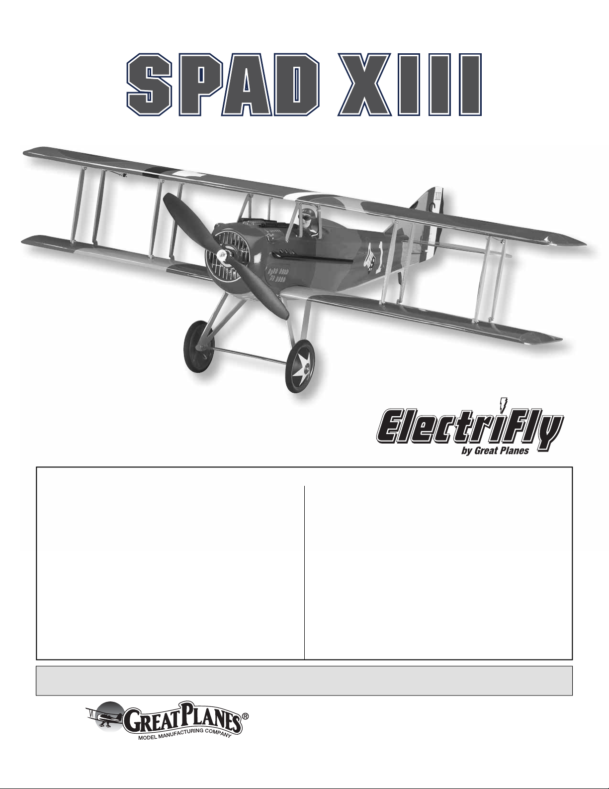
KIT CONTENTS
1
2
1. Fuselage w/Cowl, Battery Hatch
2. Wheels
3. Horizontal Stabilizer w/Elevators
5
7
6
8
9
4. Fin w/Rudder
5. Cabane Struts
6. Interplane Struts
3
4
7. Landing Gear
8. Upper Wing w/Ailerons
9. Lower Wing
ORDERING REPLACEMENT PARTS
Replacement parts for the ElectriFly SPAD XIII EP are
available using the order numbers in the Replacement Parts
List that follows. The fastest, most economical service can
be provided by your hobby dealer or mail-order company.
To locate a hobby dealer, visit the Great Planes web site
at www.greatplanes.com. Choose “Where to Buy” at the
bottom of the menu on the left side of the page. Follow the
instructions provided on the page to locate a U.S., Canadian
or International dealer.
Parts may also be ordered directly from Hobby Services by
calling (217) 398-0007, or via facsimile at (217) 398-7721,
but full retail prices and shipping and handling charges will
apply. Illinois and Nevada residents will also be charged
sales tax. If ordering via fax, include a Visa or MasterCard
number and expiration date for payment.
Mail parts orders and payments by personal check to:
Hobby Services
3002 N Apollo Drive, Suite 1
Champaign IL 61822
Be certain to specify the order number exactly as listed
in the Replacement Parts List. Payment by credit card or
personal check only; no C.O.D.
If additional assistance is required for any reason contact
Product Support by e-mail at productsupport@greatplanes.
com, or by telephone at (217) 398-8970.
Replacement Parts List
Order # Description How to Purchase
Missing pieces ....... Contact Product Support
Instruction manual . Contact Product Support
Full-size plans .......................... Not available
Contact your hobby supplier for the following parts:
GPMA3100 Top Wing
GPMA3101 Bottom Wing
GPMA3102 Fuselage w/Belly Pan
GPMA3103 Tail Surface Set
GPMA3104 Wing Struts and Cabanes Set
GPMA3105 Landing Gear Set w/Wheels
GPMA3106 Cowl, Exhaust, Guns, Battery & Servo Hatches
GPMA2997 WWI Pilot Figure
GPMA3108 Motor Mount and Hardware Bag
5
5
BEFORE YOU BEGIN
Before you begin assembling your model, inspect it for
wrinkled covering and areas where the covering may not be
tacked down adequately. Areas like the servo bay openings,
the radio antenna hole (bottom of fuse), and the slots for
the horizontal stabilizer and fi n should be tacked down
before trimming them with a knife. The covering should
be tacked down to the wood using just enough heat to
soften the adhesive backing. Low heat should be enough
to accomplish this. More heat may be required to begin to
tighten the covering.
❏ 2. Using a 4-40 x 3/4" machine screw with a washer,
temporarily install the lower wing to the fuselage. Fitting the
lower wing will help you align the horizontal tail.
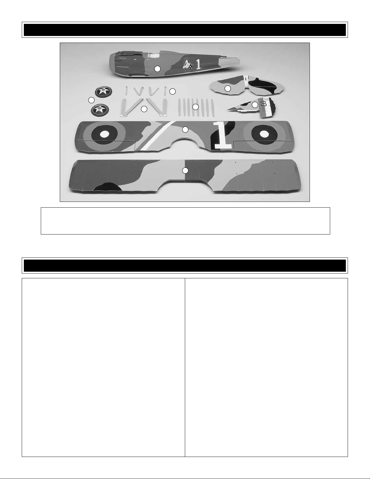
❏ 3. Lay the pre-hinged horizontal stabilizer assembly on a
fl at surface. Make sure that the elevators lie fl at on the table
and that the stab does not have any twist in it. Any twist
can be easily corrected at this point using a covering iron
on a medium heat setting. Twist the surface to the desired
position and heat the covering until it begins to shrink.
WARNINGS:
• Do not over shrink the covering or it will cause the control
surfaces or wings to twist
• Do not iron over decals
• Use only LOW heat over trim
INSTALL THE TAIL
Prepare for Tail Installation
❏ 1. Locate the wooden 3 x 20mm dowels. Holes are
provided in the leading edge of the lower wing. Test fi t each
dowel making sure that the dowel sticks out 1/4" [6mm] from
the LE of the wing. When you are satisfi ed with the fi t, wick
5 to 7 drops of thin CA into the dowel joint.
❏ 4. Insert the vertical fi n into the top of the horizontal
stabilizer. Align the fi n vertically and apply a bead of medium
CA to both sides of the joint.
666
Install the Tail to the Fuselage
AA
A = A
B = B
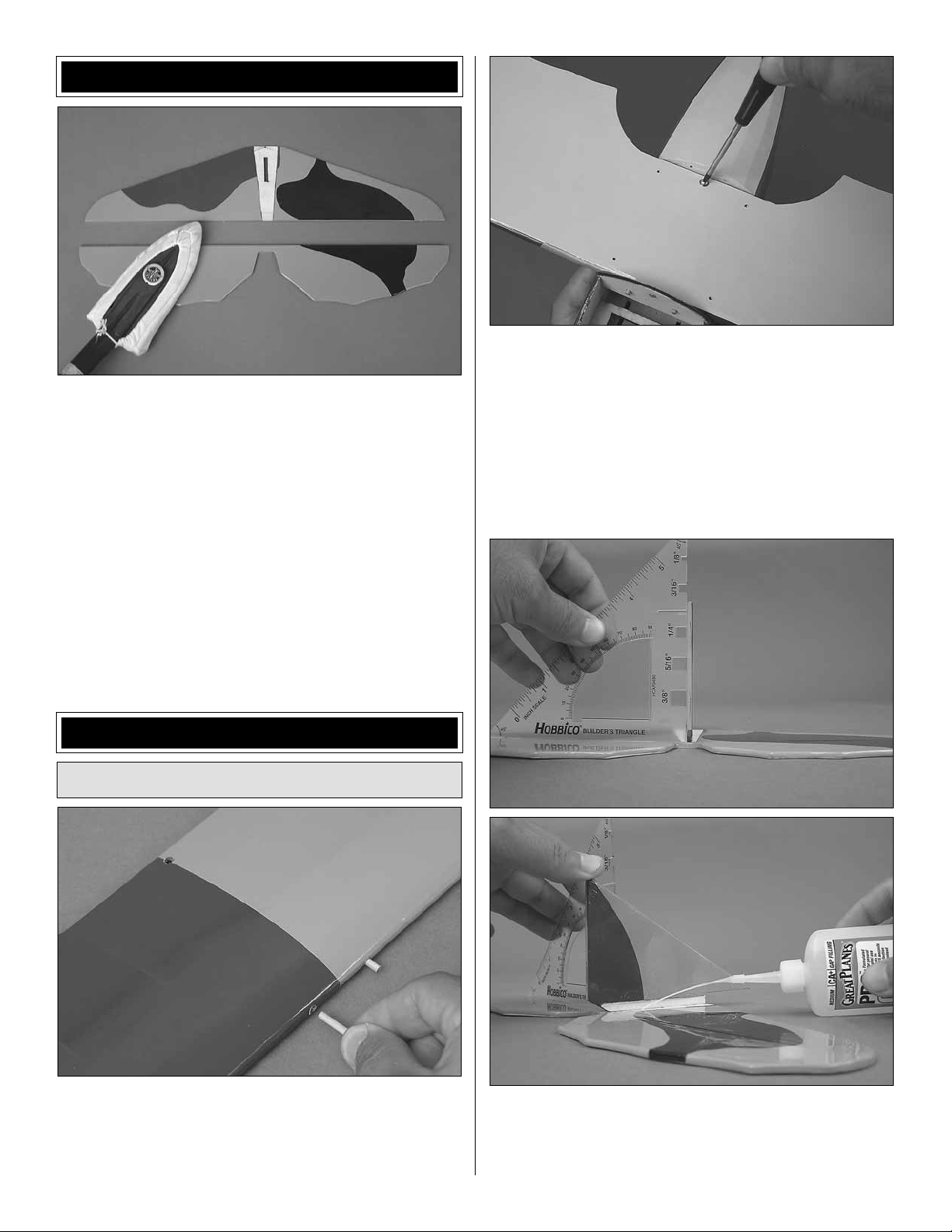
❏ 1. Remove the small block of wood protecting the upper
structure of the aft fuselage. It may be glued in place, so
a hobby knife may be needed. While you’re at it, trim away
any covering in the slots that may prevent you from having a
good glue joint when you install the tail.
❏ 2. Slide the fi n and stab into the fuselage from behind
the fuse.
B
B
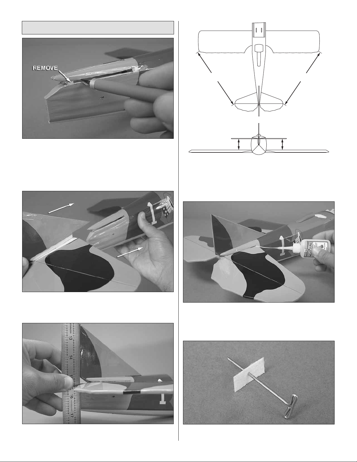
❏ 4. Align the horizontal stab so that the tips of the stab are
the same distance from the aft corner of each wing tip. Align
the horizontal stab so that it is parallel with the bottom wing.
You can do this by setting the model on a fl at surface, taking
a few steps back, and viewing it from behind.
❏ 5. When you’re satisfi ed with the positioning of the tail,
apply a bead of medium CA into the left and right stab to
fuse joints and also the fi n to fuse joint. Be sure to apply CA
to the bottom of the stab to fuse joint also.
❏ 3. Using a straight edge, align the TE of the fi n so that it is
fl ush with the TE of the fuselage.
❏ 6. Prepare three CA hinges using T-pins as shown. The T-pin
will help keep the hinge centered as you install the rudder.
7
❏ 7. Fit the three hinges into the slots of the vertical fi n. If the
slots are too tight or the hinge won’t slide in all the way, you
can use the back side of your hobby knife blade to dig them
out or make them a bit deeper.
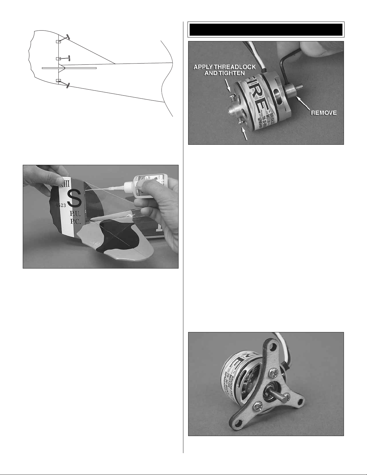
INSTALL THE MOTOR & ESC
❏ 1. Remove the steel Y-mount and the brass collar from the
motor. These will not be used.
❏ 8. Fit the rudder onto the hinges until it contacts the T-pins.
Remove the T-pins. Defl ect the rudder as you push in on it and
add at least 3 drops of thin CA to both sides of each hinge.
Let the hinges air-dry without adding any CA accelerator.
❏ 9. Remove the bottom wing from the fuselage and retain
the screw and washer.
❏ 2. Remove the two 2.5 x 6mm screws from the motor.
Apply thread locking compound to the threads and reinstall
the screws.
❏ 3. Apply thread locking compound to three 3 x 6mm screws
and use these to attach the supplied Y-mount to the motor.
8
 Loading...