

Great Planes GPMA1140 User Manual
WARRANTY
Great Planes®Model Manufacturing Co. guarantees this kit to be free from defects in both material and workmanship at the date of purchase.
This warranty does not cover any component parts damaged by use or modification. In no case shall Great Planes’ liability exceed the
original cost of the purchased kit. Fur ther, Great Planes reserves the right to change or modify this warranty without notice.
In that Great Planes has no control over the final assembly or material used for final assembly, no liability shall be assumed nor accepted for
any damage resulting from the use by the user of the final user-assembled product.By the act of using the user-assembled product, the user
accepts all resulting liability.
If the buyer is not prepared to accept the liability associated with the use of this product, the buyer is advised to return this kit
immediately in new and unused condition to the place of purchase.
To make a warranty claim send the defective part or item to Hobby Services at the address below:
Hobby Services
3002 N. Apollo Dr., Suite 1
Champaign, IL 61822
USA
Include a letter stating your name, return shipping address, as much contact information as possible (daytime telephone number, fax number,
e-mail address), a detailed description of the problem and a photocopy of the purchase receipt. Upon receipt of the package the problem will
be evaluated as quickly as possible.
READ THROUGH THIS MANUAL BEFORE STARTING
CONSTRUCTION.IT CONT AINS IMPOR T ANT INSTR UCTIONS
AND WARNINGS CONCERNING THE ASSEMBLY AND
USE OF THIS MODEL.
GPMZ1140 for GPMA1140 V1.0Entire Contents © Copyright 2006
Champaign, Illinois
(217) 398-8970, Ext 5
airsupport@greatplanes.com
INSTRUCTION MANUAL
Wingspan: 34 in [864mm]
Wing Area: 420 sq in [27.1dm2]
Weight: 1.3 – 1.5 lb [595 – 680g]
Wing Loading: 7.5 – 8.2 oz/sq ft [22 – 25g/dm2]
Length: 25.5 in [648mm]
Required (not included):
Radio: 4-channel with four micro servos
Motor: ElectriFly™RimFire™28-30-950 brushless (not included)
ESC: ElectriFly SS-25 (not included)
Battery: 11.1V, 1250mAh LiPo
™
2
INTRODUCTION ...............................................................2
AMA...................................................................................2
SAFETY PRECAUTIONS..................................................2
BATTERY CHARGER OPTIONS......................................3
ADDITIONAL ITEMS REQUIRED.....................................3
Hardware & Accessories.............................................3
Adhesives & Building Supplies....................................3
Optional Supplies & Tools ...........................................3
IMPORTANT BUILDING NOTES ......................................4
COMMON ABBREVIATIONS............................................4
ORDERING REPLACEMENT PARTS ..............................4
METRIC/INCH RULER......................................................4
KIT INSPECTION..............................................................5
KIT CONTENTS ................................................................5
PREPARATIONS ...............................................................6
ASSEMBLE THE WING ....................................................6
Install the Ailerons.......................................................6
ASSEMBLE THE FUSELAGE...........................................6
Mount the Wing...........................................................6
Mount the Stabilizer & Fin...........................................7
RADIO INSTALLATION .....................................................9
Install the Motor & ESC.................................................9
Install the Control Horns............................................10
Install the Servos.......................................................11
Install the Top Wing...................................................12
FINISH THE MODEL .......................................................14
GET THE MODEL READY TO FLY .................................16
Check the Control Directions ....................................16
Set the Control Throws..............................................16
Balance the Model (C.G.)..........................................16
Balance the Model Laterally ......................................17
PREFLIGHT.....................................................................17
Identify Your Model ....................................................17
Charge the Transmitter Batteries...............................17
Balance the Propellers..............................................17
Proper Care of Your Motor.........................................18
Ground Check...........................................................18
Range Check.............................................................18
MOTOR & BATTERY SAFETY PRECAUTIONS............18
AMA SAFETY CODE (excerpts)....................................18
CHECK LIST ...................................................................19
FLYING ............................................................................19
Takeoff.......................................................................19
Flight..........................................................................20
Landing......................................................................20
The S.E.5a is one of the most recognizable and popular of
all the WW1 Biplanes.You can now have this great looking
and flying aircraft as an electric without the mess and fuss
of a glow engine. With today’s LiPo batteries and micro
servos, small electrics have become very popular. Now
Great Planes brings you the S.E.5a in a small, easy to fly,
ARF electric. So if you want to impress your glow flying
buddies with an electric, the Great Planes S.E.5a EP ARF is
just what you need.
For the latest technical updates or manual corrections to the
S.E.5a EP ARF, visit the Great Planes web site at
www.greatplanes.com. Open the “Airplanes” link and
select the S.E.5a EP ARF. If there is new technical
information or changes to this model a “tech notice” box will
appear in the upper left corner of the page.
We urge you to join the AMA (Academy of Model
Aeronautics) and a local R/C club.The AMA is the governing
body of model aviation and membership is required to fly at
AMA clubs.Though joining the AMA provides many benefits,
one of the primary reasons to join is liability protection.
Coverage is not limited to flying at contests or on the club
field. It even applies to flying at public demonstrations and
air shows. Failure to comply with the Safety Code (excerpts
printed in the back of the manual) may endanger insurance
coverage.Additionally, training programs and instructors are
available at AMA club sites to help you get started the right
way. There are over 2,500 AMA chartered clubs across the
country. Contact the AMA at the address or toll-free phone
number below.
IMPORTANT!!! T wo of the most important things you can do
to preserve the radio controlled aircraft hobby are to avoid
flying near full-scale aircraft and avoid flying near or over
groups of people.
1.Your S.E.5a EP ARF should not be considered a toy, but
rather a sophisticated, working model that functions very
much like a full-size airplane. Because of its performance
capabilities, the S.E.5a EP ARF, if not assembled and
operated correctly, could possibly cause injury to yourself or
spectators and damage to property.
PRO TECT YOUR MODEL,YOURSELF
& OTHERS...FOLLOW THESE
IMPORTANT SAFETY PRECAUTIONS
Academy of Model Aeronautics
5151 East Memorial Drive
Muncie, IN 47302
Tele: (800) 435-9262
Fax (765) 741-0057
Or via the Internet at:
http://www.modelaircraft.org
AMA
INTRODUCTION
TABLE OF CONTENTS

2. You must assemble the model according to the
instructions. Do not alter or modify the model, as doing so
may result in an unsafe or unflyable model. In a few cases
the instructions may differ slightly from the photos.In those
instances the written instructions should be considered
as correct.
3.You must take time to build straight, true and strong.
4. You must use an R/C radio system that is in firstclass condition.
5.You must correctly install all R/C and other components so
that the model operates correctly on the ground and in the air .
6.You must check the operation of the model before every
flight to insure that all equipment is operating and that the
model has remained structurally sound. Be sure to check
clevises or other connectors often and replace them if they
show any signs of wear or fatigue.
7. If you are not an experienced pilot or have not flown this
type of model before, we recommend that you get the
assistance of an experienced pilot in your R/C club for your
first flights.If you’ re not a member of a club, your local hob by
shop has information about clubs in your area whose
membership includes experienced pilots.
Remember:Take your time and follow the instructions to
end up with a well-built model that is straight and true.
The Great Planes S.E.5a EP ARF is designed for use with
LiPo batteries only. All LiPo batteries require a charger
specifically designed for charging LiPo batteries.The use of
a charger not designed for charging LiPo batteries will result
in damage to the batteries and possibly a fire.
We recommend the use of the Great Planes Triton™DC
Peak Charger (GPMM3150), the ElectriFly™DC PolyCharge
™
(GPMM3010) or for charging more than one battery at a
time the ElectriFly PolyCharge4 (GPMM3015).
In addition to the items listed in the “
BATTERY CHARGER
OPTIONS”
section, the following is the list of hardware and
accessories required to finish the S.E.5a EP ARF. Order
numbers are provided in parentheses.
❏ 4-Channel radio with four micro servos
❏ (1) ElectriFly SS-25 25 amp brushless ESC (GPMM1820)
❏ (1) ElectriFly 3.5mm Bullet
™
(male) to 2mm Bullet
(female) connector adapter (GPMM3122)
❏ (1) ElectriFly 1250mAh LiPo 3-cell battery (GPMP0823)
❏ (1) Futaba
®
R114F 4-channel FM receiver
(FUTL0443, FUTL0442)
❏ (2) 12" [305mm] Futaba extensions (FUTM4507)
❏ (1) Futaba “Y-harness” (FUTM4130)
❏ (1) ElectriFly RimFire C28-30-950 brushless
motor (GPMG4560)
❏ (1) 10x4.5 Prop (GPMQ6660)
❏ (1) 3mm Prop adapter (GPMQ4959)
In addition to common household tools and hobby tools, this
is the “short list”of the most important items required to build
the S.E.5a EP ARF.
Great Planes Pro™CA and Epoxy glue
are recommended.
❏ 1 oz. [28g] Thin Pro CA (GPMR6002)
❏ #1 Hobby knife (HCAR0105)
❏ #11 Blades (5-pack, HCAR0211)
❏ Medium T-pins (100, HCAR5150)
❏ Builder’s Triangle Set (HCAR0480)
❏ K & S #801 Kevlar
®
thread or string (for stab alignment)
❏ Pliers
❏ Wire cutter
❏ Top Flite
®
MonoKote®heat gun (TOPR2000)
❏ Clear tape
Here is a list of optional tools mentioned in the manual that
will help you build the S.E.5a EP ARF.
❏ Stick-on segmented lead weights (GPMQ4485)
❏ Top Flite MonoKote sealing iron (TOPR2100)
❏ Top Flite Hot Sock
™
iron cover (TOPR2175)
❏ 2 oz. [57g] Spray CA activator (GPMR6035)
❏ CA applicator tips (HCAR3780)
❏ CA debonder (GPMR6039)
❏ Robart Super Stand II (ROBP1402)
❏ CG Machine
™
(GPMR2400)
❏ Precision Magnetic Prop Balancer
™
(TOPQ5700)
Optional Supplies & Tools
Adhesives & Building Supplies
Hardware & Accessories
ADDITIONAL ITEMS REQUIRED
BATTERY CHARGER OPTIONS
We, as the kit manuf acturer, provide you with a top quality ,
thoroughly tested kit and instructions, but ultimately the
quality and flyability of your finished model depends on
how you build it; therefore, we cannot in any way
guarantee the performance of your completed model, and
no representations are expressed or implied as to the
performance or safety of your completed model.
3

• When you see the term
test fit
in the instructions, it means
that you should first position the part on the assembly
without using any glue, and then slightly modify or
custom fit
the part as necessar y for the best fit.
•
Photos
and
sketches
are placed before the step they
refer to. Frequently you can study photos in following
steps to get another view of the same parts.
• The stabilizer and wing incidences and motor thrust
angles have been factory-built into this model. However,
some technically-minded modelers may wish to check
these measurements anyway. To view this information
visit the web site at www.greatplanes.com and click on
“Technical Data.” Due to manufacturing tolerances
which will have little or no effect on the way your model
will fly, please expect slight deviations between your
model and the published values.
Fuse = Fuselage
Stab = Horizontal Stabilizer
Fin = Ver tical Fin
LE = Leading Edge
TE = Trailing Edge
LG = Landing Gear
Ply = Plywood
" = Inches
mm = Millimeters
ESC = Electronic Speed Control
Replacement parts for the Great Planes S.E.5a EP ARF are
available using the order numbers in the Replacement Parts
List that follows.The fastest, most economical service can be
provided by your hobby dealer or mail-order company.
To locate a hobby dealer, visit the Hobbico®web site at
www.hobbico.com. Choose “Where to Buy” at the bottom
of the menu on the left side of the page. Follow the
instructions provided on the page to locate a U.S., Canadian
or International dealer.
Parts may also be ordered directly from Hobby Services by
calling (217) 398-0007, or via facsimile at (217) 398-7721,
but full retail prices and shipping and handling charges will
apply. Illinois and Nevada residents will also be charged
sales tax. If ordering via fax, include a Visa®or MasterCard
®
number and expiration date for payment.
Mail parts orders and payments by personal check to:
Hobby Services
3002 N. Apollo Drive, Suite 1
Champaign, IL 61822
Be certain to specify the order number exactly as listed in
the Replacement Parts List. Payment by credit card or
personal check only; no C.O.D.
If additional assistance is required for any reason contact Product
Support by e-mail at productsupport@greatplanes.com, or by
telephone at (217) 398-8970.
Description How to Purchase
Missing pieces Contact Product Support
Instruction manual Contact Product Support
Kit parts listed below Hobby Supplier
Replacement Parts List
GPMA3000..............Upper Wing Set
GPMA3001..............Lower Wing Set
GPMA3002..............Fuse Set
GPMA3003..............Tail Surface Set
GPMA3004..............Cowl
GPMA3005..............Cabanes Set
GPMA3006..............Interplane Set
GPMA3007..............Machine Gun Set
GPMA3008..............Exhaust Stack Set
GPMA3009..............Landing Gear
GPMA3010..............Wheels (2)
GPMA3011..............Pilot
ORDERING REPLACEMENT PARTS
COMMON ABBREVIATIONS
IMPORTANT BUILDING NOTES
4
To convert inches to millimeters, multiply inches by 25.4
5
Before starting to build, take an inventory of this kit to make sure it is complete, and inspect the parts to make sure they
are of acceptable quality. If any parts are missing or are not of acceptable quality, or if you need assistance with assembly ,
contact Product Support. When reporting defective or missing parts, use the part names exactly as they are written in
the Kit Contents list.
Great Planes Product Support
3002 N. Apollo Drive , Suite 1
Champaign, IL 61822
Telephone: (217) 398-8970, ext. 5
Fax: (217) 398-7721
E-mail: airsupport@greatplanes.com
KIT INSPECTION
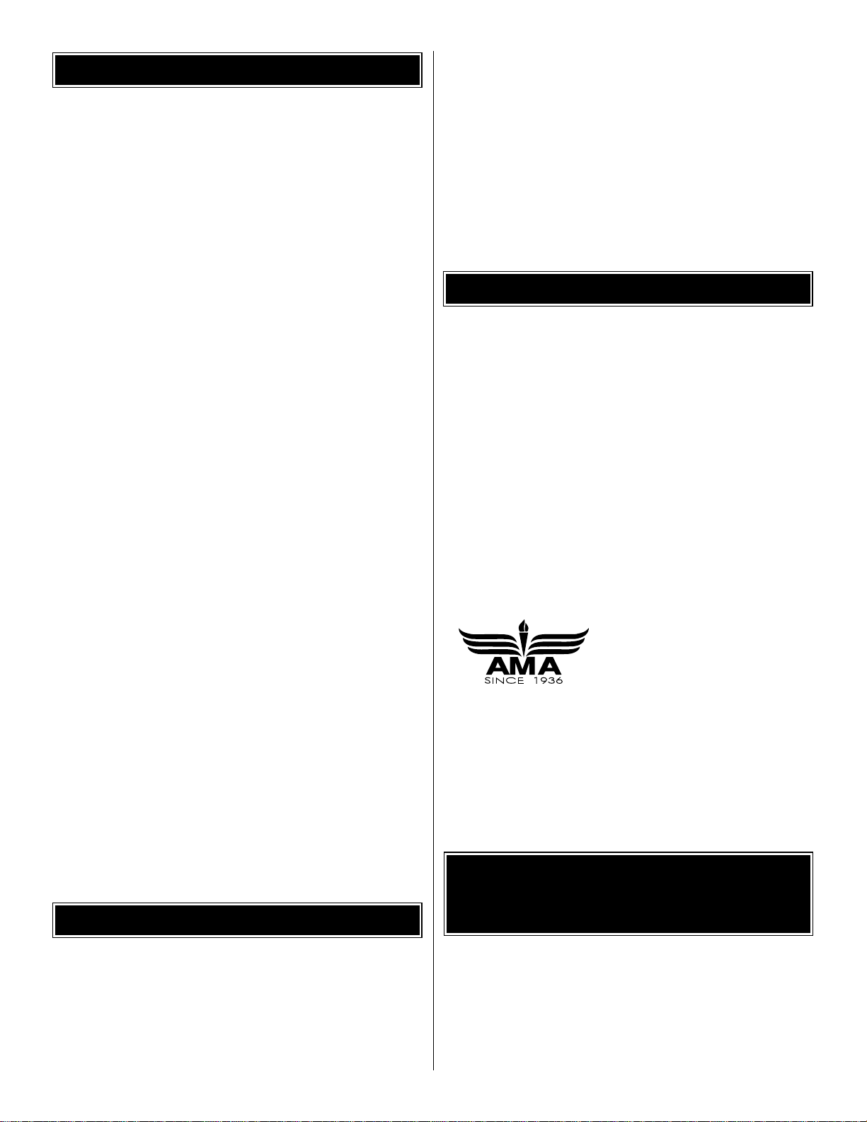
1. Radiator
2. Fuselage
3. Battery Hatch
4. Hook & Loop Material
5. Exhaust (L&R)
6. Machine Gun
7. Outer Wing Struts (2 long, 2 short)
8. Long Cabanes (2)
9. Short Cabanes (2)
10. Landing Gear Supports (2)
11. Main Landing Gear
12. Stabilizer & Elevator
13. Fin & Rudder
14. Top Wing
15. Bottom Wing
(3) 3 x 6mm Machine Screws
(8) 2 x 7mm Self-Tapping Screws
(4) 35mm Aileron Pushrod
(4) 25mm Heat-Shrink Tubing
(4) #1 Strut Mounts
(2) #2 Strut Mounts
(2) #3 Strut Mounts
(1) Plywood Motor Mount
(3) Aluminum Tubes
(3) 3 x 26mm Machine Screws
(7) 3mm Washers
(2) 460mm Pushrods
(4) Control Horns
(2) Screw-Lock Pushrod Connectors
(2) Screw-Lock Nylon Retainers
(1) Double-Sided Tape
(2) Aileron Servo Hatch
(1) 3 x 18mm Machine Screw
(4) Straight Control Horn
(1) Hook & Loop Material
(14) 2 x 8mm Self-Tapping Washer
Head Screw
(2) 100mm Pushrod Z-Bend One End
(2) 100mm Pushrod L-Bend One End
(2) Plastic Pushrod Retainer
(2) 2 x 9mm Machine Screw
(2) 2mm Washer
(2) 2 x 5mm Flat Head Machine Screw
Kit Contents (photographed)
Kit Contents (not photographed)
KIT CONTENTS
2
15
1
3
7
5
8
9
12
13
14
10
11
6
4
❏ 1. If you have not done so already, remove the major
parts of the kit from the box (wing, fuselage, tail parts, etc.)
and inspect them for damage. If any par ts are damaged or
missing, contact Product Support at the address or
telephone number on page 5.
❏ 2. Separate the ailerons from the wing, the rudder from
the fin and the elevator from the stabilizer.If necessary, use
a covering iron set on medium/high to carefully tighten the
covering.Lay the control surface on a flat surface and apply
pressure over sheeted areas to thoroughly bond the
covering to the wood. Hint: Poke three or four pin holes in
the covering over the open structure in the tail surf aces .This
will allow the hot air to escape while tightening the covering.
Warning:Do not over shrink the co vering or it will cause
the control surfaces to twist.
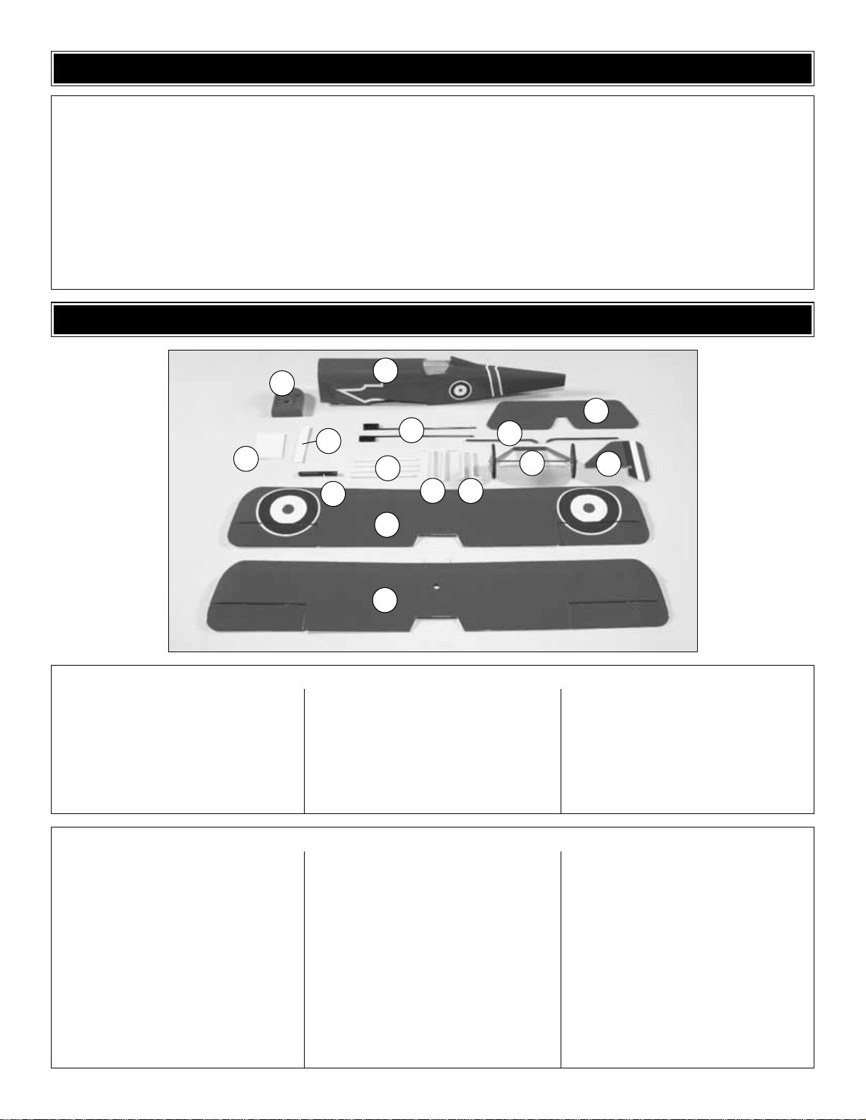
❏❏1.Test fit the r ight aileron to the bottom wing with two
6.4 x 15mm hinges.If the hinges don’t stay centered, stick a
pin through the middle of the hinges to hold them in position
while fitting the aileron to the wing.
❏❏2. Remove any pins you may have inserted into the
hinges. Adjust the aileron so there is a very small gap
between the LE of the aileron and the wing.The gap should
be small – just enough to see light through or to slip a piece
of paper through.
❏❏3. Apply three drops of thin CA to the top and bottom of
each hinge. Do not use CA accelerator. After the CA has
cured, test the hinges by pulling on the ailerons.
❏ 4.Now join the other aileron to the bottom wing using the
same procedure.
❏ 5. Repeat the process of installing the ailerons on the
top wing.
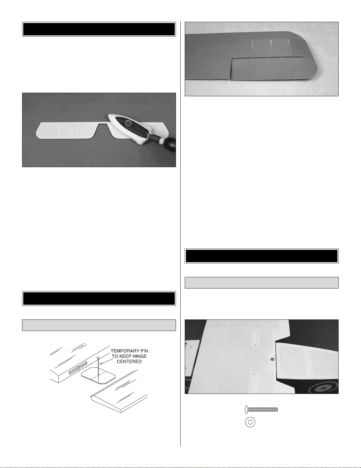
❏ 1. Trim the covering from the bolt hole at the TE of the
bottom wing.
❏ 2.Test fit the wing to the fuselage and bolt it into position
with a 3 x 18mm machine screw and 3mm washer.
Mount the Wing
ASSEMBLE THE FUSELAGE
Install the Ailerons
ASSEMBLE THE WING
PREPARATIONS
6
 Loading...