

Page 1
SPECIFICATIONS
INSTRUCTION MANUAL
Wingspan: 26.5 in [675mm]
Length: 29.5 in [750mm]
Wing Area: 382 sq in
[24.6dm
2
]
Motor:
ElectriFly™
(28-22-1380) Brushless
Weight: 9–10 oz
Wing
Loading:
[255 –285g]
3.4–3.8 oz/sq ft
[10–12g/dm
2
Propeller: APC 9 r 4.7 (APCQ5010)
]
ESC: Electrifly™ SS-12
WARRANTY
Great Planes® Model Manufacturing Co. guarantees this kit to
be free from defects in both material and workmanship at the
date of purchase. This warranty does not cover any component
parts damaged by use or modification. In no case shall Great
Planes’ liability exceed the original cost of the purchased kit.
Further, Great Planes reserves the right to change or modify this
warranty without notice.
In that Great Planes has no control over the final assembly or
material used for final assembly, no liability shall be assumed nor
accepted for any damage resulting from the use by the user of
the final user-assembled product. By the act of using the
user-assembled product, the user accepts all resulting liability.
If the buyer is not prepared to accept the liability associated
with the use of this product, the buyer is advised to return
Battery: Great Planes
11.1V, 300mAh 20C
RimFire™ 300
Competition BP Series LiPo
Radio: 6−7 channel minimum with
mixing capability, 6 channel
micro reciever and four micro
servos w/ minimum 19 oz-in
of torque
this kit immediately in new and unused condition to the
place of purchase.
To make a warranty claim send the defective part or item to
Hobby Services at the address below:
Hobby Services
3002 N. Apollo Dr. Suite 1
Champaign IL 61822 USA
Include a letter stating your name, return shipping address, as
much contact information as possible (daytime telephone
number, fax number, e-mail address), a detailed description of
the problem and a photocopy of the purchase receipt. Upon
receipt of the package the problem will be evaluated as quickly
as possible.
READ THROUGH THIS MANUAL BEFORE STARTING CONSTRUCTION. IT CONTAINS IMPORTANT
INSTRUCTIONS AND WARNINGS CONCERNING THE ASSEMBLY AND USE OF THIS MODEL.
Entire Contents © Copyright 2009
Champaign, Illinois
(217) 398-8970, Ext 5
airsupport@greatplanes.com
GPMA1135 Mnl
Page 2
TABLE of CONTENTS
modelers’ rights and interests and is required to fl y at most
R/C sites.
INTRODUCTION . . . . . . . . . . . . . . . . . . . . . . . . . . . . . . . . 2
AMA. . . . . . . . . . . . . . . . . . . . . . . . . . . . . . . . . . . . . . . 2
SAFETY PRECAUTIONS. . . . . . . . . . . . . . . . . . . . . . . . . . 2
DECISIONS YOU MUST MAKE. . . . . . . . . . . . . . . . . . . . . 3
Motor, Battery and ESC Recommendations . . . . . . . . 3
Propeller. . . . . . . . . . . . . . . . . . . . . . . . . . . . . . . . . . . . 3
Radio Equipment . . . . . . . . . . . . . . . . . . . . . . . . . . . . . 3
Adhesives and Building Supplies. . . . . . . . . . . . . . . . . 3
IMPORTANT BUILDING NOTES . . . . . . . . . . . . . . . . . . . . 3
KIT INSPECTION. . . . . . . . . . . . . . . . . . . . . . . . . . . . . . . . 3
ORDERING REPLACEMENT PARTS . . . . . . . . . . . . . . . . 3
KIT CONTENTS. . . . . . . . . . . . . . . . . . . . . . . . . . . . . . . . . 4
ASSEMBLE THE FUSELAGE . . . . . . . . . . . . . . . . . . . . . . 4
INSTALL THE MOTOR, BATTERIES AND ESC. . . . . . . . . 7
INSTALL THE SERV OS,
PUSHRODS AND CONTROL HORNS . . . . . . . . . . . . 8
INSTALL THE BRACING WIRES . . . . . . . . . . . . . . . . . . . 11
GET THE MODEL READY TO FLY. . . . . . . . . . . . . . . . . . 12
Mixing Set Up. . . . . . . . . . . . . . . . . . . . . . . . . . . . . . . 12
Set the Control Throws. . . . . . . . . . . . . . . . . . . . . . . . 13
Install the Propeller . . . . . . . . . . . . . . . . . . . . . . . . . . 14
Balance the Model (C.G.). . . . . . . . . . . . . . . . . . . . . . 14
PREFLIGHT . . . . . . . . . . . . . . . . . . . . . . . . . . . . . . . . . . . 14
Identify Your Model. . . . . . . . . . . . . . . . . . . . . . . . . . . 14
Charge the Batteries . . . . . . . . . . . . . . . . . . . . . . . . . 14
Balance Propellers. . . . . . . . . . . . . . . . . . . . . . . . . . . 14
Ground Check and Range Check . . . . . . . . . . . . . . . 15
AMA SAFETY CODE . . . . . . . . . . . . . . . . . . . . . . . . . . . . 15
GENERAL . . . . . . . . . . . . . . . . . . . . . . . . . . . . . . . . . 15
RADIO CONTROL. . . . . . . . . . . . . . . . . . . . . . . . . . . 15
CHECK LIST . . . . . . . . . . . . . . . . . . . . . . . . . . . . . . . . . . 15
FLYING. . . . . . . . . . . . . . . . . . . . . . . . . . . . . . . . . . . . . . . 15
Trimming the Model . . . . . . . . . . . . . . . . . . . . . . . . . . 15
Takeoff . . . . . . . . . . . . . . . . . . . . . . . . . . . . . . . . . . . . 16
Transition to Forward Flight . . . . . . . . . . . . . . . . . . . . 16
Flight . . . . . . . . . . . . . . . . . . . . . . . . . . . . . . . . . . . . . 16
Landing . . . . . . . . . . . . . . . . . . . . . . . . . . . . . . . . . . . 16
INTRODUCTION
Academy of Model Aeronautics Tele. (800) 435-9262
5151 East Memorial Drive Fax (765) 741-0057
Muncie, IN 47302-9252
Or via the Internet at:
http://www.modelaircraft.org
IMPORTANT!!!
Two of the most important things you can do to preserve the
radio controlled aircraft hobby are to avoid fl ying near fullscale aircraft and avoid fl ying near or over groups of people.
FOLLOW THESE
IMPORTANT SAFETY PRECAUTIONS
PROTECT YOUR MODEL, YOURSELF & OTHERS…
1. Your VFO Pogo should not be considered a toy, but rather
a sophisticated, working model that functions very much like
a full-size airplane. Because of its performance capabilities,
the VFO P ogo, if not assemb led and operated correctly , could
possibly cause injury to yourself or spectators and damage
to property.
2. Y ou must assemble the model according to the instructions.
Do not alter or modify the model, as doing so may result in an
unsafe or unfl yable model. In a few cases the instructions may
differ slightly from the photos. In those instances the written
instructions should be considered as correct.
3. You must take time to build straight, true and strong.
4. Y ou must use an R/C radio system that is in good condition,
a correctly sized engine, and other components as specifi ed
in this instruction manual. All components must be correctly
installed so that the model operates correctly on the ground
and in the air. You must check the operation of the model and
all components before every fl ight.
The VFO Pogo is one of the most interesting airplanes
you may ever fl y. Though it may look challenging, a pilot
with intermediate fl ying skills can master this airplane with
a little practice. For the latest technical updates or manual
corrections to the VFO P ogo visit the Great Planes web site at
www.g reatplanes.com. Open the “Airplanes” link, then select
the VFO Pogo ARF. If there is new technical information or
changes to this model a “tech notice” box will appear in the
upper left corner of the page.
AMA – Academy of Model Aeronautics
If you are not already a member of the AMA, please join!
The AMA is the governing body of model aviation and
membership provides liability insurance coverage, protects
5. If you are not an experienced pilot or have not fl own
this type of model before, we recommend that you get the
assistance of an experienced pilot in your R/C club for
your fi rst fl ights. If you’re not a member of a club, your local
hobby shop has information about clubs in your area whose
membership includes experienced pilots.
We, as the kit manuf acturer, provide you with a top quality,
thoroughly tested kit and instructions, but ultimately the
quality and fl yability of your fi nished model depends
on how you build it; therefore, we cannot in any way
guarantee the performance of your completed model,
and no representations are expressed or implied as to the
performance or safety of your completed model.
2
Page 3

Remember: Take your time and follow the instructions to
end up with a well-built model that is straight and true.
Adhesives and Building Supplies
DECISIONS YOU MUST MAKE
This is a list of items required to fi nish the VFO Pogo that
may require planning or decision making before starting to
build. Order numbers are provided in parentheses.
Motor, Battery and
ESC Recommendations
Motor
• The RimFire 300 (GPMG4505) motor provides plenty
of power and good fl ight times. You will also require a
12 amp ESC.
Batteries
• Great Planes LiPo 11.1V 300mAh 20C Competition
BP Series (GPMP0701)
• Great Planes ElectriFly LiPo 11.1V 640mAh 15C BP
Series (GPMP0705)
ESC
• The ElectriFly SS 12 (GPMM1810) is the perfect
complement to the RimFire 300 motor.
This is the list of hardware and accessories required to fi nish
the Pogo.
• 1 oz. [30g] Pro
™
CA Foam Safe CA+Medium glue
• 2 oz. [57g] spray CA activator (GPMR6035)
• #1 Hobby knife (HCAR0105)
• #11 blades (5-pack, HCAR0211)
IMPORTANT BUILDING NOTES
• When you see the term test fi t in the instructions, it means
that you should fi rst position the part on the assembly
without using any glue, then slightly modify or custom fi t
the part as necessary for the best fi t.
• Whenever the term glue is written you should rely upon
your experience to decide what type of glue to use. When
a specifi c type of adhesive works best for that step, the
instructions will make a recommendation.
• Photos and sketches are placed before the step they
refer to . F requently you can study photos in f ollowing steps
to get another view of the same parts.
Propeller
• We tried a few different props and had the best
performance with the APC 9 x 4.7 (APCQ5010).
Radio Equipment
Though the VFO Pogo is basically a four channel airplane,
it does require mixing capabilities that you will not fi nd on
most four channel radios. For that reason you need a six or
seven channel radio with electronic mixes, or the use of “Y”
connectors to link the two rudder halves and elev ator halv es.
The choice of radio is dependent on the brand of radio you
use and its capabilities. The Futaba® 7C (FUTJ66**) seven
channel radio system is the minimum radio requirement
within the Futaba line of radios. Other brands may offer you
the required mixes in a six channel radio.
With a radio with electronic mixes, you will mix the ailerons
and rudder and the ailerons and one additional channel to
make the control surfaces work together as four ailerons.
You will also need a third mix to mix the rudder and one
additional channel to allow the two rudder control surfaces
to move together.
KIT INSPECTION
Before starting to build, take an inventory of this kit to make
sure it is complete, and inspect the parts to make sure they
are of acceptable quality . If any parts are missing or are not of
acceptable quality, or if you need assistance with assembly,
contact Product Support. When reporting defective or
missing parts, use the part names exactly as they are written
in the Kit Contents list.
Great Planes Product Support
3002 N Apollo Drive, Suite 1 Ph: (217) 398-8970, ext. 5
Champaign, IL 61822 Fax: (217) 398-7721
E-mail: airsupport@greatplanes.com
ORDERING REPLACEMENT PARTS
Missing parts may be ordered directly from Hobby
Services by calling (217) 398-0007, or via facsimile at
(217) 398-7721.
• Four Micro servos with at least 19 oz-in of torque –
Futaba S3114
• 6 channel micro servo. R606FS 6 channel 2.4GHz
(FUTL7635) R146IP 72MHz (FUTL0601)
If additional assistance is required for any reason contact
Product Support by e-mail at productsupport@greatplanes.
com, or by telephone at (217) 398-8970.
3
Page 4
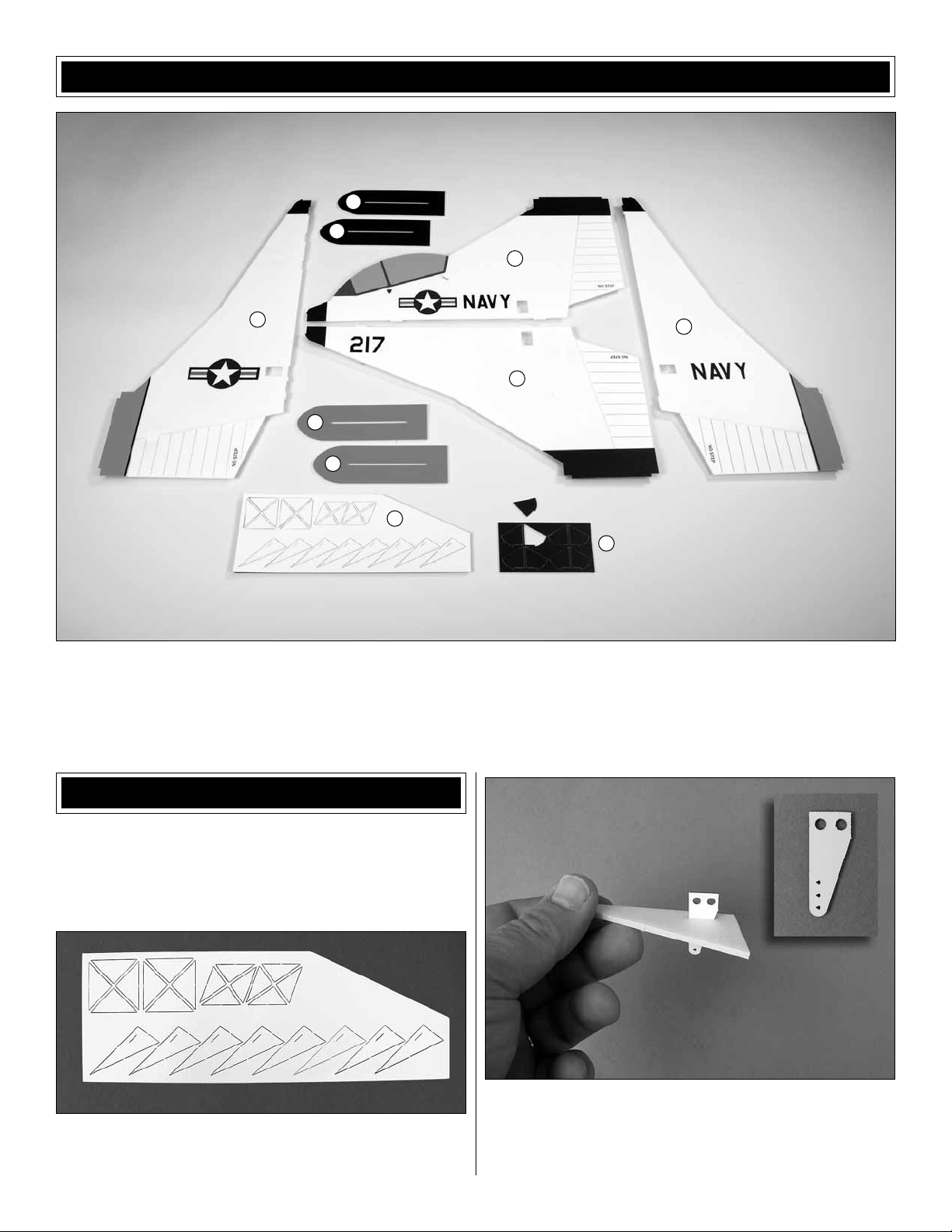
KIT CONTENTS
5
5
1
3
5
5
1. Fuselage Top
2. Fuselage Bottom
3. Left Wing
4. Right Wing
4
2
6
7
5. Pods
6. Doubler Sheet (white)
7. Doubler Sheet (black)
ASSEMBLE the FUSELAGE
IMPORTANT! Throughout the building process you will be
instructed to glue parts together with CA glue. You must use
“Foam Safe” CA glue. If you choose to use a CA activator it
too must be “Foam Safe”.
Remove the long triangles from the foam sheet.
❏ 1.
Locate one of the plywood control horns. Slide the
❏ 2.
horn into each of the slots in the triangle pieces to open the
slot to fi t the horn.
4
Page 5
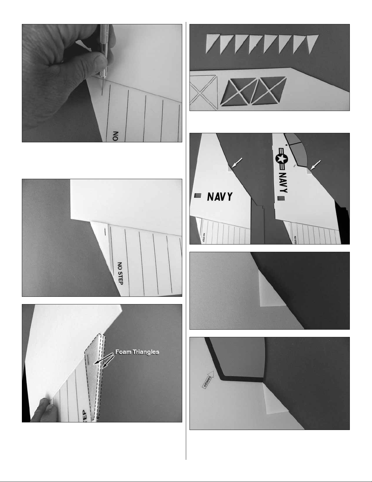
Each of the control surfaces comes pre-taped. The
❏ 3.
tape partially covers the slot in the control surface. Use a
hobby knife to cut the tape that covers the slot.
Remove the small triangles from the foam sheet.
❏ 5.
Glue the triangles in place onto both sides of each
❏ 4.
control surface. Be sure the slots in the triangles align with
the slot in each control surface.
Glue a triangle onto each side of each of the four
❏ 6.
fuselage parts. The triangle is glued to the trailing edge of
the fuselage side where shown.
5
Page 6

L
S
Lay the two wing halves side by side and then glue
❏ 7.
them together with medium or thick CA. Hold the two halves
tightly together until the glue has cured.
Glue the top half of the fuselage to the top of the wing
❏ 8.
with medium or thick CA. After the glue has cured repeat this
step for the bottom half of the fuselage.
S
L
S
11. Repeat step 10 until all of the doublers are glued
❏
into place.
L
S
L
9. Remove the black motor mount doublers from the
❏
foam sheet they are attached to . Examine them closely. Four
doublers are shorter than the other four. Separate them into
four long and four short doublers.
10. Glue one of the long doublers in place on the front
❏
of one of the fuselage sides. Glue a shorter doubler to the
fuselage side next to it.
12. Locate four 1/4" x 3" [6mm x 76mm] carbon fi ber
❏
strips. Glue them to the bottom of each of the orange and
black fuselage pods.
13. Glue the or ange pods to the or ange wing tips and the
❏
black pods to the black wing tips.
6
Page 7

INSTALL the MOTOR,
BATTERIES and ESC
14. Look closely at the orange and black wing tips. There
❏
is a very light line embossed. Using that line as a reference,
mark a short line onto the back of the pod.
15. Remove the remaining
❏
triangles from the foam
sheet. Glue one to each side
of the wing and pod on the
reference lines.
1. Locate the plywood motor mount. Position it on the
❏
fuselage so that the top screw mounting hole is in line with
the fuselage. Glue the mount to the front of the fuselage.
2. Depending on the confi guration of your motor you may
❏
need to make clearance behind the fi rewall for the motor
shaft. Place your motor on the mount to see if any foam
makes contact with any part of the motor. Remove the foam
under the mount as needed. This can be done with a high
speed motor tool, a drill bit or a soldering iron. If you use
a soldering iron, test the temperature of the iron on a foam
scrap to be sure the heat is not so hot that you cannot control
the rate that the foam melts.
7
Page 8

3. Secure the motor to the mount with three 1/8" x 3/8"
❏
[3mm x 10mm] screws.
4. From one of the two 4" [102mm] Velcro strips, cut 1"
❏
[25mm].
6. Plug the wires from your motor and ESC together.
❏
Apply the 1" [25mm] piece of Velcro to the back of the ESC
and then apply it to the fuselage. To keep the wires in place
against the fuselage side, you may wish to use a bit of hot
melt glue or tape.
INSTALL the SERVOS, PUSHRODS
and CONTROL HORNS
1. For adequate control movement you will need a
❏
minimum 1" [25mm] servo arm.
5. From the larger piece of the Velcro you cut, apply one
❏
half of the Velcro so that the top edge of the Velcro is 2"
[51mm] below the bottom edge of the painted black nose.
The other half of Velcro is applied to the back of y our battery.
The Velcro secures the battery to the fuselage.
2. Center the servo and then install the servo arm onto the
❏
servo as shown. Drill out the outer two holes in the control
horn with a #57 or .043 drill bit.
8
Page 9

Before proceeding, look at these two pictures to understand
the orientation for the servo as it is fi t into the servo mounting
hole.
3. Position the servo against the servo opening. Make
❏
marks on the fuselage where the servo mounting tabs contact
the fuselage. Cut the foam on those marks. Slide the servo
into the slots you cut. For now, leave the servo in the opening
secured only with the friction of the foam. You will permanently
mount the servos to the fuselage in a future step.
5. The servo leads need to be routed to the side of the
❏
fuselage where the speed control is mounted. The wires
pass through the small square openings in the fuselage.
❏ ❏ ❏
servos.
4. Repeat steps 2 and 3 for the remaining three
6. From the remaining Velcro, cut a piece large enough to
❏
fi t your receiver. Install the receiver to the fuselage making
sure that you position it so the wire leads from the ESC and
the servos can reach the receiver without the use of any
servo extensions.
9
Page 10

Before we go any further in the assembly process, y ou need
to set up the mixing required to fl y the model. W e e xplain this
on page 12, “Mixing Set Up”. After you have the radio set up
with the correct mixing, proceed with the next step.
8. The control rods are made up of eight 5/64" [2mm]
❏
pre-bent steel wires, four 5/64" [2mm] carbon rods and eight
pieces of heat shrink tubing.
7. Plug your servos into the appropriate channels and
❏
route your receiver antenna.
9. With the servo centered, install one of the metal control
❏
wires into the outer hole in the servo arm and one in the
second hole from the end of the control horn in the control
10
Page 11

surface. Slip the carbon rod and the heat shrink tubing
together to the metal wires. Do this f or all f our servos . Do not
shrink the tubing yet. You will do this in a later step.
10. Tur n on the radio system and slowly move the sticks
❏
on the radio to be sure that the control surfaces move the
correct direction as instructed on page 12, Mixing Set Up.
INSTALL the BRACING WIRES
11. With the radio system on and the control surfaces
❏
centered, shrink the tubing around the wires with a soldering
iron. When shrinking the tube be sure to center the carbon
rod between the metal control wires. Do this for all four
servos.
12. The last thing remaining is to secure the servos to the
❏
foam. For our installation we used CA glue to mount them
to the foam. You could also use a low temperature hot melt
glue. This will secure them in place but also make it easier
to remove the servo. Before gluing the servos in place you
may also wish to sav e some weight b y cutting off the unused
servo arm from your servos.
This completes the radio component installation.
1. Locate the four 1/32" x 19-3/4" [0.8mm x 500mm]
❏
carbon rods. These are used to brace and stiff en the fuselage.
Press the end of the carbon rod through the surface of the
foam but not through the outside skin of the f oam. Locate the
large foam triangle and then place it against two sides of the
fuselage to assure they are perpendicular to each other. Trim
the opposite end of the carbon rod so that it is the proper
length to allow the end of the carbon rod to be inserted into
the foam skin. When you are satisfi ed that everything is
square and the carbon rods are the correct length, glue the
carbon rod to the foam.
11
Page 12

2. Glue the 1/32" x 12" [0.8mm x 300mm] carbon rods into
❏
the foam doublers using the same method used in step one.
Note: By only utilizing the ailerons in the roll axis, the roll
rate will be “slower/softer” than if you mixed the rudder with
the ailerons in a transmitter that utilizes multiple mixes.
GET the MODEL READY to FLY
Mixing Set Up
1. Turn on the transmitter and plug the battery into the
❏
receiver . If you f ollowed the assembly instructions your controls
should all be centered. If not, see if you can center the trims
with your radio. If you cannot, you need to remove the heat
shrink tubing from the pushrods and re-adjust the pushrods.
2. This airplane requires the use of a couple of different
❏
mixes. With the large number of different radios on the
market it is impossible to provide exact instructions for all
of them so we have attempted to give you the basic mixes
you will need to set up the VFO Pogo. You will need to refer
to the instruction manual for your radio to understand ho w to
achieve the mixes explained here. You will fi nd it helpful to
refer to the photographs that follow in the next section.
Set-up for a six channel radio with limited mixing capability
To be able to set the VFO control surfaces using a standard
radio, the radio system must have a “fl ying wing/elevon”
type of confi guration in the software, meaning it must have
a function that has aileron and elevator pre-mixed in the
transmitter. This confi guration uses two servos to operate
both the elevators and ailerons . If you set-up the VFO in this
confi guration you will need a “Y” harness extension to run
the two rudder servos off the rudder port in the receiver.
Mix #1, “Ailerons” - All of the control surfaces must move
to provide enough roll control for the model. Be sure that
all of the surfaces move as shown when operated with your
transmitter.
Activate the function in the transmitter so that the ailerons
are working properly and in the correct direction. Check the
elevator function in the same manner and adjust the throws
in the ATV or similar function in the transmitter.
12
Page 13

Mix #2, “Elevator” - The left and right elevator halves must
move in the same direction.
Set the Control Throws
To ensure a successful fi rst fl ight, set up your VFO Pogo
according to the control throws specifi ed in this manual.
The throws have been determined through actual fl ight
testing and accurate record-keeping, allowing the model
to perform in the manner in which it was intended. If, after
you have become accustomed to the way the VFO Pogo
fl ies, you would like to change the throws to suit your
taste, that is fi ne. However, too much control throw could
make the model too responsive and diffi cult to control, so
remember, “more is not always better.”
1. Hold a ruler on your w orkbench against the widest part
❏
of the trailing edge of the elevator. Note the measurement
on the ruler.
Mix #3, “Rudder” - The upper and lower rudders need
to be mixed so that they move in the same direction.
Option without mixing - Use a “Y” connector to link the
two rudder halves.
2. Mo v e the elev ator up with y our transmitter and mo ve the
❏
ruler forward so it will remain contacting the trailing edge. The
distance the elevator mo ves up from center is the “up” ele vator
throw . Measure the down elevator throw the same way.
3. If necessary, adjust the ATVs in your transmitter
❏
to increase or decrease the throw according to the
measurements in the control throws chart.
4. Measure and set the low rate elevator throws and the
❏
high and low rate throws for the rest of the control surfaces
the same way.
NOTE: The throws are measured at the widest part of the
elevators, rudder and ailerons.
These are the recommended control surface throws:
ELEVATOR
RUDDER
AILERONS
HIGH RATE
UP
3-3/4"
[95mm]
56 deg
RIGHT
3-1/2"
[89mm]
51 deg
UP
3"
[76mm]
42 deg
DOWN
3-3/4"
[95mm]
56 deg
LEFT
3-1/2"
[89mm]
51 deg
DOWN
3"
[76mm]
42 deg
LOW RATE
UP
3"
[76mm]
42 deg
RIGHT
2-3/4"
[70mm]
38 deg
UP
2-1/2"
[64mm]
34 deg
DOWN
3"
[76mm]
42 deg
LEFT
2-3/4"
[70mm]
38 deg
DOWN
2-1/2"
[64mm]
34 deg
13
Page 14

We also found that using 40% exponential helped
controllability. For Futaba radios this is -40%. On other
brands the exponential may need to be +40%. See your
radio’s instruction manual to determine proper setting.
Install the Propeller
3. If the tail drops, the model is “tail heavy.” Move the
❏
battery pack and/or receiver forward to get the model to
balance. If the nose drops, the model is “nose heavy.” Move
the battery pack and/or receiver aft.
4. After moving the battery re-check the C.G.
❏
1. Install the propeller to the motor with the “O” ring
❏
supplied with the motor.
Balance the Model (C.G.)
More than any other factor, the C.G. (center of gravity/
balance point) can have the greatest effect on how a
model fl ies and could determine whether or not your fi rst
fl ight will be successful. If you value your model and wish
to enjoy it for many fl ights, DO NOT OVERLOOK THIS
IMPORTANT PROCEDURE. A model that is not properly
balanced may be unstable and possibly unfl yable.
At this stage the model should be in ready-to-fl y condition
with all of the components in place including the complete
radio system, motor, battery and prop.
1. Use a fi ne-point felt tip pen to mark lines on the bottom
❏
of the wing on both sides of the fuselage 12" [305mm] back
from the nose of the fuselage.
This is where your model should balance for the fi rst
fl ights. Later, you may experiment by shifting the C.G. 1/2”
[13mm] forward or 1/2” [13mm] back to change the fl ying
characteristics. Moving the C.G. forward will improve the
smoothness and stability, but the model will then be less
aerobatic (which may be fi ne for less-experienced pilots).
Moving the C.G. aft makes the model more maneuver able
and aerobatic for experienced pilots. In any case, start at
the recommended balance point and do not at any time
balance the model outside the specifi ed range.
PREFLIGHT
Identify Your Model
No matter if you fl y at an AMA sanctioned R/C club site or
if you fl y somewhere on your own, you should always have
your name, address, telephone number and AMA number
on your model. It is required at all AMA R/C club fl ying sites
and AMA sanctioned fl ying events. Fill out the identifi cation
tag on page 16 and place it on your model.
Charge the Batteries
Follow the battery charging instructions that came with your
radio control system to charge the batteries. You should
always charge your transmitter and receiver batteries the night
before you go fl ying, and at other times as recommended by
the radio manufacturer.
Balance Propellers
2. With the wing attached to the fuselage, all parts of the
❏
model installed including the battery (ready to fl y), lift it at the
balance point you marked.
Carefully balance your propeller and spare propellers before
you fl y . An unbalanced prop can be the single most signifi cant
cause of vibration that can damage your model. Not only
will engine mounting screws and bolts loosen, possibly with
disastrous effect, but vibration may also damage your radio
receiver and battery. Vibration can also cause your fuel to
foam, which will, in turn, cause your engine to run hot or quit.
We use a Top Flite Precision Magnetic Prop Balancer
(TOPQ5700) in the workshop and keep a Great Planes
Fingertip Prop Balancer (GPMQ5000) in our fl ight box.
14
Page 15

Ground Check and Range Check
Always ground chec k the operational r ange of y our radio before
the fi rst fl ight of the day following the manuf acturer’ s instructions
that came with your radio. This should be done once with the
motor off and once with the motor running at various speeds. If
the control surfaces do not respond correctly, do not fl y! Find
and correct the problem fi rst.
AMA SAFETY CODE
Read and abide by the following excerpts from the Academy of
Model Aeronautics Safety Code. For the complete Safety Code
refer to Model Aviation magazine, the AMA web site or the Code
that came with your AMA license.
9) Under no circumstances may a pilot or other person touch
a powered model in fl ight; nor should any part of the model
other than the landing gear, intentionally touch the ground,
except while landing.
CHECK LIST
During the last few moments of preparation your mind may be
elsewhere anticipating the excitement of the fi rst fl ight. Because
of this, you may be more likely to overlook certain checks and
procedures that should be performed before the model is fl own.
To help avoid this, a check list is provided to make sure these
important areas are not overlooked. Many are covered in the
instruction manual, so where appropriate, refer to the manual for
complete instructions. Be sure to chec k the items off as they are
completed (that’s wh y it’s called a check list!).
General
1) I will not fl y my model aircraft in sanctioned events, air
shows, or model fl ying demonstrations until it has been proven
to be airworthy by having been previously, successfully fl ight
tested.
2) I will not fl y my model aircraft higher than approximately 400
feet within 3 miles of an airport without notifying the airport
operator. I will give right-of-way and avoid fl ying in the proximity
of full-scale aircraft. Where necessary, an observer shall be
utilized to supervise fl ying to avoid having models fl y in the
proximity of full-scale aircraft.
3) Where established, I will abide by the safety rules for the
fl ying site I use, and I will not willfully and deliberately fl y my
models in a careless, reckless and/or dangerous manner.
5) I will not fl y my model unless it is identifi ed with my name and
address or AMA number, on or in the model. Note: This does not
apply to models while being fl own indoors.
7) I will not operate models with pyrotechnics (any device that
explodes, burns, or propels a projectile of any kind).
Radio Control
1) I will have completed a successful radio equipment ground
check before the fi rst fl ight of a new or repaired model.
2) I will not fl y my model aircraft in the presence of spectators
until I become a qualifi ed fl ier, unless assisted by an e xperienced
helper.
3) At all fl ying sites a straight or curved line(s) must be
established in front of which all fl ying takes place with the other
side for spectators. Only personnel involved with fl ying the
aircraft are allowed at or in the front of the fl ight line. Intentional
fl ying behind the fl ight line is prohibited.
4) I will operate my model using only radio control frequencies
currently allowed by the Federal Communications Commission.
5) I will not knowingly operate my model within three miles
of any pre-existing fl ying site except in accordance with the
frequency sharing agreement listed [in the complete AMA
Safety Code].
1. Check the C.G. according to the measurements provided
❏
in the manual.
2. Be certain the battery and receiver are securely mounted
❏
to the fuse.
3. Confi r m that all controls operate in the correct direction
❏
and the throws are set up according to the manual.
4. Balance your propeller (and spare propellers).
❏
5. Tighten the propeller nut and spinner.
❏
6. Place your name, address, AMA number and telephone
❏
number on your model.
7. If you wish to photograph your model, do so before your
❏
fi rst fl ight.
8. Range chec k your radio when you get to the fl ying site.
❏
FLYING
The Pogo is obviously a different kind of airplane that is
going to take a slightly different approach to taking off and
landing.
The following gives you an idea of the best way to achieve a
successful fi rst fl ight of the VFO Pogo. It is important to become
familiar with the fl ight instructions before attempting to fl y the
Pogo . In addition to these fl ight instructions we have also posted
an instructive video that will explain and show the fi rst fl ights of
the model. Log onto “www.electrifl y.com/parkfl yers/gpma1135.
html” and review the video. Once you view the video you will
see and understand just how easy and fun the airplane can be.
Trimming the Model
Before attempting your fi rst fl ight you should trim the model. It
is best to do the trimming and fl ying of the Pogo indoors. If you
must do it outdoors there must be very little or no wind. The
easiest way to trim the Pogo is with a helper. First, be sure your
helper is wearing safety glasses. Have him hold the airplane in
both hands as shown on the following page.
15
Page 16

Apply the throttle until there is enough power to allow the
airplane to hover. Have your helper let go of the airplane but
keep the airplane in his hands between his fi ngers. This way
he can quickly grab the airplane if it is out of trim. As the helper
releases and again grabs the airplane, observe which way the
airplane pitches. You will have to pay attention to the orientation
of the model so that you adjust the correct control surface. If the
plane is pitching up or down, make adjustment to the elev ator. If
the airplane is rolling, adjust the ailerons. If it falls to the left or
right, adjust the rudder. Continue with these adjustments until
the airplane appears to be reasonably close to being trimmed.
Takeoff
This is the part you have been waiting for. Your natural impulse
is to take off slowly to get to hover. This does not work! When
you attempt a slow take off the airplane wants to spin from the
motor torque and you have to fi ght this with aileron input. The
best way to take off is to quickly pop the Pogo off the ground
to about eye level. Once you are hovering three to four feet
[0.9–1.2m] off of the ground you need to keep a close eye on
what the airplane does. Because of its design it is important to
pay close attention to the orientation of the airplane so that you
can make the correct adjustments. When ho vering or just barely
pulling forward, the airplane is quite stable and controllable. If
you try to make adjustments and the airplane is descending,
you will fi nd that it is a little harder to control. You will be tempted
to over control the airplane but the model will stabilize without
too much input from you.
Most likely you will want to practice popping the airplane to a
three foot [0.9m] hover and then reducing po wer to settle it bac k
onto the ground to get familiar with Pogo.
25–30°
To fl y the airplane slow you need to keep it pointed up at a
25 to 30 degree angle. As you fl atten the angle of attack you
will see the airplane really picks up speed.
Flight
Once you are in forward fl ight the airplane will perf orm really
tight loops, very fast rolls and tight turns with the rudder.
You will enjoy fl ying and then pulling the nose up to slow
the airplane and then transition to hover. Just be sure to
pay close attention to the orientation of the airplane so you
respond with the correct control inputs.
Landing
For your fi rst couple of fl ights you should begin to practice
transitioning from forward fl ight to hover right away so that
you can get the sense of what you will need to do when
you land. To initiate the landing fl y the airplane slowly at an
altitude of three to six feet. When you are in front of yourself
pull the nose up and add a little more power so the airplane
is hovering. Slowly decrease the pow er until the plane settles
on the ground.
I really encourage you to go to the web site and watch the
video. If the old sa ying, “A picture is worth a thousand words”
is true then our video will make it very clear how to succeed
with your Pogo.
Remember to think.
Have a ball! But always stay in control
and fl y in a safe manner.
GOOD LUCK and GREAT FLYING!
Transition to Forward Flight
From the hov er, simply apply some down elev ator and the Pogo
easily goes into forward fl ight. At this point the airplane fl ies as
any conventional aircraft. The airplane responds pretty quickly
so be sure to pay attention to its orientation. In f orw ard fl ight the
Pogo can fl y very fast or very slow. It is best to fl y the airplane
slowly until you get accustomed to it.
16
Name
Address
City, State, Zip
This model belongs to:
AMA Number
Phone Number
 Loading...