

Page 1
INSTRUCTION MANUAL
™
Wingspan: 30 in [760mm]
Wing Area: 332 sq in [21.4 dm2]
Weight: 7.5 – 8.0 oz. [215 – 225g]
Wing Loading: 3.3 – 3.4 oz/sq ft [10 – 11 g/dm2]
Length: 22 in [545mm]
Radio: 3-Channel with two micro servos
Motor: RimFire™ 250 (28-13-1750kV),
WARRANTY
Great Planes® Model Manufacturing Co. guarantees this kit to
be free from defects in both material and workmanship at the date
of purchase. This warranty does not cover any component parts
damaged by use or modifi cation. In no case shall Great Planes’
liability exceed the original cost of the purchased kit. Further,
Great Planes reserves the right to change or modify this warranty
without notice.
In that Great Planes has no control over the fi nal assembly or
material used for fi nal assembly, no liability shall be assumed nor
accepted for any damage resulting from the use by the user of
the fi nal user-assembled product. By the act of using the userassembled product, the user accepts all resulting liability.
If the buyer is not prepared to accept the liability associated
with the use of this product, the buyer is advised to return
7.4V (2S) LiPo 300mAh, SS-8 ESC
this kit immediately in new and unused condition to the place
of purchase.
To make a warranty claim send the defective part or item to Hobby
Services at the address below:
Hobby Services
3002 N. Apollo Dr., Suite 1
Champaign, IL 61822 USA
Include a letter stating your name, return shipping address, as
much contact information as possible (daytime telephone number,
fax number, e-mail address), a detailed description of the problem
and a photocopy of the purchase receipt. Upon receipt of the
package, the problem will be evaluated as quickly as possible.
READ THROUGH THIS MANUAL BEFORE STARTING CONSTRUCTION. IT CONTAINS IMPORTANT
INSTRUCTIONS AND WARNINGS CONCERNING THE ASSEMBLY AND USE OF THIS MODEL.
Entire Contents © Copyright 2008
Champaign, Illinois
(217) 398-8970, Ext 5
airsupport@greatplanes.com
GPMA1133Mnl1.0
Page 2
TABLE OF CONTENTS
AMA
INTRODUCTION ............................................................... 2
PRECAUTIONS ................................................................. 2
DECISIONS YOU MUST MAKE ........................................ 3
Motor, Battery, ESC Recommendations .................... 3
Radio Equipment ......................................................3
ADDITIONAL ITEMS REQUIRED .................................... 3
KIT INSPECTION .............................................................. 3
KIT CONTENTS ................................................................ 3
ASSEMBLY ....................................................................... 4
Join the Bottom Wing to the Fuselage ....................... 4
Join the Stab and Fin to the Fuselage ....................... 4
Hook up the Elevator and Rudder .............................. 6
Mount the Motor, ESC and Battery ............................ 6
Mount the Top Wing and Main Landing Gear ............. 7
Attach the Cowl and Add the Decals .........................8
OPTIONAL: Add the Flying Wires .............................. 9
GET THE MODEL READY TO FLY ................................. 10
Check the Control Directions ................................... 10
Set the Control Throws ............................................ 10
Balance the Model (C.G.).........................................11
PREFLIGHT .................................................................... 11
Charge the Batteries ................................................ 11
Balance Propellers ................................................... 11
MOTOR SAFETY PRECAUTIONS ...................Back Cover
FLYING ..............................................................Back Cover
Ground Check and Range Check ..............Back Cover
Flight ..........................................................Back Cover
If you are not already a member of the AMA, please join! The
AMA is the governing body of model aviation and membership
provides liability insurance coverage, protects modelers’ rights
and interests and is required to fl y at most R/C sites.
Academy of Model Aeronautics
5151 East Memorial Drive
Muncie, IN 47302
Tele: (800) 435-9262
Fax (765) 741-0057
Or via the Internet at:
http://www.modelaircraft.org
IMPORTANT!!! Two of the most important things you can do
to preserve the radio controlled aircraft hobby are to avoid
fl ying near full-scale aircraft and avoid fl ying near or over
groups of people.
PROTECT YOUR MODEL, YOURSELF
& OTHERS...FOLLOW THESE
IMPORTANT SAFETY PRECAUTIONS
1. Your Sopwith Pup should not be considered a toy, but rather
a sophisticated, working model that functions very much like a
full-size airplane. Because of its performance capabilities, the
Pup, if not assembled and operated correctly, could possibly
cause injury to yourself or spectators and damage to property.
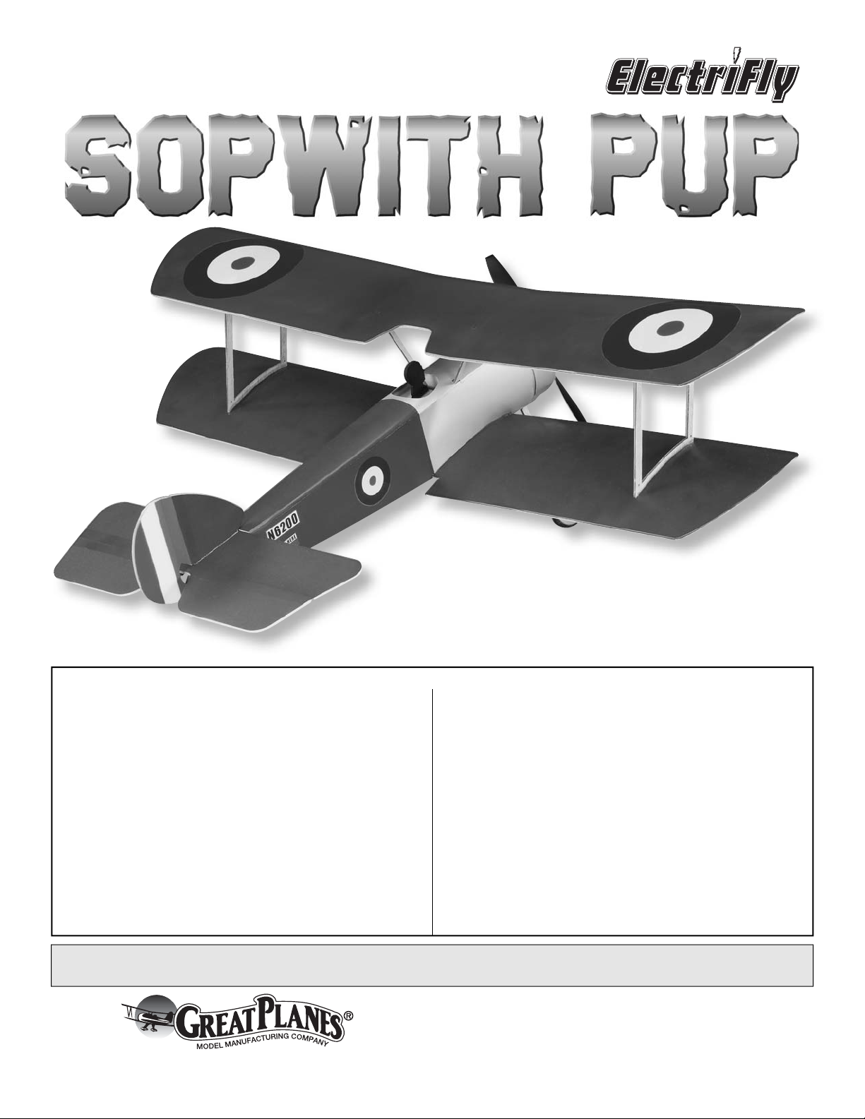
INTRODUCTION
Thank you for purchasing the ElectriFly Sopwith Pup Slow
Flyer EP ARF. Obviously, the Pup was intended for indoor
fl ying, but is also fun to fl y outdoors on calm evenings or in
the morning when the winds are still calm.
For the latest technical updates or manual corrections
to the Sopwith Pup, visit the Great Planes web site at
www.greatplanes.com. Open the “Airplanes” link, then
select the ElectriFly Sopwith Pup ARF. If there is new technical
information or changes to this model a “tech notice” box will
appear in the upper left corner of the page.
2. You must assemble the model according to the instructions.
Do not alter or modify the model, as doing so may result in an
unsafe or unfl yable model. In a few cases the instructions may
differ slightly from the photos. In those instances the written
instructions should be considered as correct.
3. You must take time to build straight, true and strong.
4. You must use an R/C radio system that is in good condition,
a correctly sized engine, and other components as specifi ed
in this instruction manual. All components must be correctly
installed so that the model operates correctly on the ground
and in the air. You must check the operation of the model and
all components before every fl ight.
5. If you are not an experienced pilot or have not fl own
this type of model before, we recommend that you get the
assistance of an experienced pilot in your R/C club for
your fi rst fl ights. If you’re not a member of a club, your local
hobby shop has information about clubs in your area whose
membership includes experienced pilots.
6. While this kit has been fl ight tested to exceed normal use,
if the plane will be used for extremely high stress fl ying, such
as aggressive aerobatics, or if a motor larger than one in the
recommended range is used, the modeler is responsible
for taking steps to reinforce the high stress points and/or
substituting hardware more suitable for the increased stress.
2
Page 3
We, as the kit manufacturer, provide you with a top quality,
thoroughly tested kit and instructions, but ultimately the
quality and fl yability of your fi nished model depends
on how you build it; therefore, we cannot in any way
guarantee the performance of your completed model,
and no representations are expressed or implied as to
the performance or safety of your completed model.
Remember: Take your time and follow the instructions to
end up with a well-built model that is straight and true.
Radio Equipment
The ElectriFly Sopwith Pup is designed to fl y on three
channels—elevator, rudder and throttle. Two ES40 Pico
Micro Servos (GPMM1200) are recommended and are
featured in this manual. A minimum 3-channel receiver is
also required.
ADDITIONAL ITEMS REQUIRED
DECISIONS YOU MUST MAKE
This is a partial list of items required to fi nish the Sopwith Pup
that may require planning or decision making before starting to
build. Order numbers are provided in parentheses.
Motor, Battery and ESC
Recommendations
The ElectriFly Sopwith Pup was designed to fl y with a RimFire
250 (28-13-1750kV) Outrunner Motor (GPMG4502)
powered by either a 7.4V (2S) 300mAh ElectriFly Power
Series LiPo Battery (GPMP0594) or a 7.4V (2S) 300mAh
ElectriFly Competition BP LiPo Battery (GPMP0700). The
Power Series battery will allow the Pup to fl y longer, but the
Competition BP is lighter weight and will provide more power.
An ElectriFly SS-8 8 Amp Brushless ESC (electronic speed
control) is also required (GPMM1800).
Finally, a suitable propeller such as a Great Planes 8 x 6
Power Flow Slo-Flyer Electric Propeller (GPMQ6610, qty.
2) will also be required.
In addition to common hobby tools, this is the list of additional
accessories and building supplies required to fi nish the Pup.
Order numbers are provided in parentheses.
❏ Medium foam-safe CA (GPMR6069)
❏ J&Z R/C-56 white glue (or any household white glue)
❏ Optional: Black thread or string for fl ying wires (see page 8)
KIT INSPECTION
Before starting to build, take an inventory of this kit to make
sure it is complete, and inspect the parts to make sure they
are of acceptable quality. If any parts are missing or are not of
acceptable quality, or if you need assistance with assembly,
contact Product Support.
Great Planes Product Support
3002 N Apollo Drive, Suite 1
Champaign, IL 61822
Telephone: (217) 398-8970, ext. 5
Fax: (217) 398-7721
E-mail: airsupport@greatplanes.com
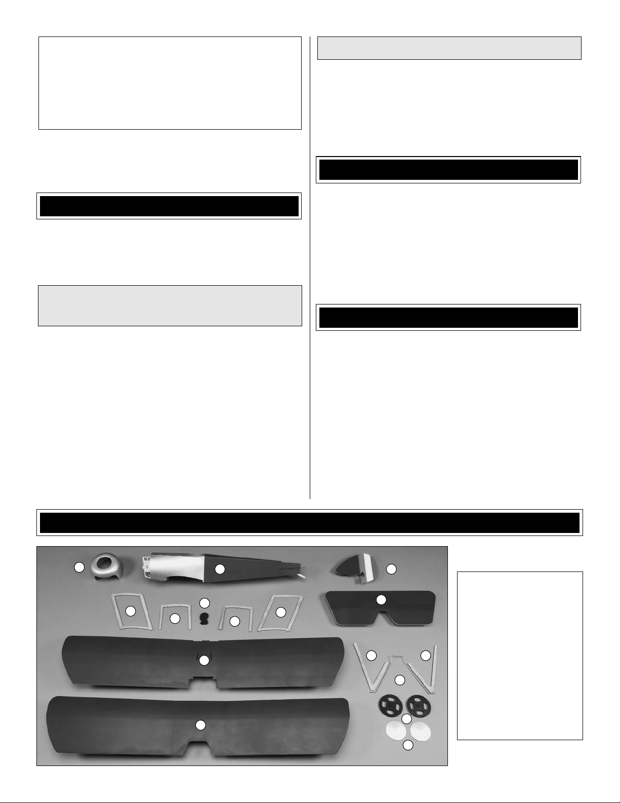
KIT CONTENTS
1
5
6
2 3
7
5
6
8
9
3
4
10 10
11
12
13
1. Cowl
2. Fuselage
3. Vertical Stabilizer
4. Horizontal Stabilizer
5. Struts (2)
6. Cabanes (2)
7. Pilot
8. Bottom Wing
9. Top Wing
10. Landing Gear Covers (2)
11. Landing Gear Wire
12. Wheels (2)
13. Wheel Covers (2)
Page 4
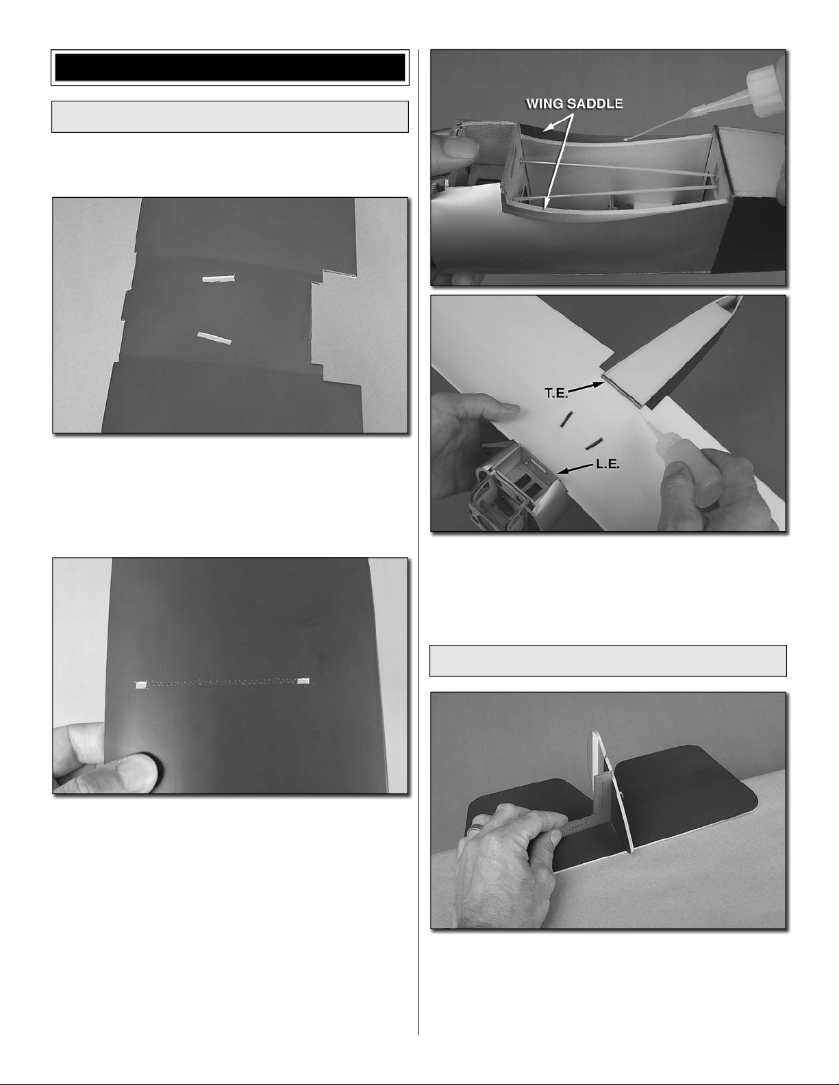
ASSEMBLY
Join the Bottom Wing to the Fuselage
The bottom wing is done fi rst so it can be used as a reference
for aligning the horizontal stabilizer.
❏ 1. Use a sharp hobby knife to cut the skin from the top of
the bottom wing over the landing gear slots. Also cut the skin
from the slots near both ends of the wing for the struts.
❏ 2. Using a pin with a straightedge as a guide, perforate
the skin of the bottom wing between the outer strut slots
as shown, but don’t poke the holes all the way through to
the bottom. These perforations will strengthen the glue bond
between the struts and wing.
❏ 3. Test fi t the bottom wing to the fuselage. When satisfi ed
with the fi t, apply a generous bead of foam-safe CA to both
wing saddles on the fuselage, and then place the wing into
position. Also glue the leading and trailing edges of the wings
to the balsa formers.
Join the Stab and Fin to the Fuselage
❏ 1. Glue the vertical stabilizer (fi n) to the horizontal stabilizer
(stab) using a small builder’s square to make sure they are
perpendicular. Note: Don’t build up a large fi llet of CA. Later,
after the model has been completed, all of the glue joints
will be reinforced with white glue (such as R/C 56 or regular
white glue).
4
Page 5

AA'
A = A'
❏ 2. Hold the stab/fi n assembly into position on the fuselage.
View the alignment of the stab and wing from behind. If the
stab and wing are not parallel with each other, use a sharp
hobby knife to carefully trim the “high side” of the stab saddle
to achieve the alignment.
❏ 5. Use foam-safe CA to securely glue the horn into position.
❏ 6. Glue the plywood horn keeper to the other side of the
horn and to the top of the elevator.
❏ 3. Once the stab aligns with the wing, hold the assembly
to the fuselage. Center the LE of the fi n with the top of
the fuselage and the LE of the rudder with the back of the
fuselage. Securely glue the stab into position. Reinforce the
joint by gluing from the bottom up inside the fuselage.
❏ 4. As shown in the photo, fi t one of the plywood control
horns to the Z-bend on the end of the elevator pushrod
(already in the fuselage). Fit the horn into the slot in the
bottom of the elevator. Use a sharp #11 hobby knife to cut
the hinge tape from the slot on the top of the elevator so the
horn will go all the way through. Note: If the pushrod is too
long it may be bumping up against the former in the front of
the servo compartment—cut the pushrod if necessary, but
cut only enough to allow the horn to fi t—otherwise you may
inadvertently cut the wire too short.
❏ 7. Fit the other horn and keeper to the rudder pushrod and
glue them to the rudder the same way.
5
Page 6

Hook Up the Elevator and Rudder
K
Refer to this picture while hooking up
the elevator and rudder.
1/4"
[6.5mm]
5/16"
[8mm]
Mount the Motor, ESC and Battery
❏ 1. Cut a 1-1/4" x 1/2" [32 x 12mm] strip from the “rough”
side of the adhesive-backed hook-and-loop strip that
came with this kit. Stick the strip to the back of the fi rewall
brace just behind the fi rewall. This is where the battery will
be mounted.
ELEVATOR
RUDDER
❏ 1. In order to achieve the correct elevator and rudder throws
specifi ed on page 11, the pushrods need to be connected to
the servo arms as shown. If your servo arms don’t already
have holes that are the correct distance out, drill new holes in
the servo arms you will be using and cut off the unused arms.
❏ 2. Place the elevator and rudder servos in the servo tray in
the fuselage. Temporarily connect the servos to your receiver
with the battery and ESC so you can power the system up.
Note: With 3-channel models such as this (where there are
no ailerons), it is common to connect the rudder servo into
the “aileron” channel in the receiver. This way, the right stick
will still be used for turning the model. If it is your preference
however, you may connect the rudder servo into the rudder
channel instead.
SCREW-LOC
CONNECTOR
❏ 3. Turn on your
transmitter and plug in
the battery and center the
servos. Connect screwlock connectors to the
servo arms. Then fi t the
arms onto the servos.
SERVO ARM
NYLON
RETAINER
❏ 4. Connect the pushrods to the screw-lock connectors on
the servo arms, and center the elevator and rudder. Then,
with a drop of threadlocker on the screws, tighten the screws
in the screw-lock connectors to lock the pushrods down.
❏ 5. Use CA to glue the servos into position. Install the screws
that hold the servo arms onto the servo output shafts.
❏ 2. Mount the motor with the included (3) 2 x 5mm Phillips
wood screws. Use the included adhesive-backed hook-andloop strips, or double-sided foam tape (not included), to
mount the receiver and ESC. Guide excess wiring behind
each component inside the fuselage.
6
Page 7

❏ 3. If you’ve mounted a 2.4GHz receiver as shown in the
photo, guide one of the antennas back through the fuselage.
The other antenna will be looped around the inside of the
cowl when it is mounted later. If you've mounted a 72MHz
receiver, guide the antenna down and out the bottom of the
fuselage. Tape the antenna to the bottom of the fuselage in a
few places so it will not get caught in the wheels or propeller
or drag on the ground.
❏ 4. Test fi t the cowl to make sure none of the wiring or the
ESC or receiver interfere with the fi t.
Mount the Top Wing
and the Landing Gear
Refer to this picture while mounting the top wing.
from the bottom to make certain top wing is parallel with the
bottom wing by “eyeballing” the leading edges. If necessary,
trim the notches for the cabanes in the top wing to get it
parallel with the bottom wing.
❏ 3. Holding the top wing to the cabanes in alignment with the
bottom wing, glue the wing to the cabanes. Without adding
any twist to the wings, glue the wing struts into position.
TIGHTER CURVE
(FORWARD)
❏ 1. Test fi t the cabanes into the fuselage so they are facing
the correct direction as illustrated—the part with the “tighter
curve” on the top goes forward. If necessary, trim the cutouts
in the thin, plastic fuselage top so the cabanes fi t easily, then
glue them into position.
❏ 4. Wipe any residual oil or fi lm from the main landing gear
wire using a small paper towel scrap and denatured alcohol.
Roughen the gear with medium-grit sandpaper so glue will
adhere. Fit the gear into position. Note that it sweeps back.
Note: The gear could be permanently glued into position,
but it should fi t tight enough so that no glue is required.
❏ 2. Test fi t the top wing to the cabanes by fi tting the tabs
of the cabanes into the notches in the wing. View the model
❏ 5. Test fi t, then use CA to glue the plywood landing gear
covers onto the gear wire. If necessary, trim the slots in the
bottom wing to accommodate the braces.
7
Page 8

❏ 6. Fit the wheels onto the gear followed by the small, black
nylon wheel retainers.
Attach the Cowl and Add the Decals
❏ 1. Before attaching the cowl, connect your battery and turn
on the radio and momentarily power up the motor to make
sure it is turning the correct direction (counterclockwise when
viewed from the front). If the motor is turning backwards, switch
any two wires between the motor and ESC with each other.
❏ 2. Fit the cowl into position. If using a 2.4GHz receiver,
loop the second antenna (that is not inside the fuselage)
around the inside of the cowl. Use a few pieces of clear
tape to hold the cowl in place. Mount the propeller with the
propeller saver O-ring.
❏ 7. Glue the wheel covers to the wheels—it may be
necessary to cut a portion of the gear wire protruding from
the wheel retainers to accommodate the covers. An easy way
to glue on the hubs is to hold the plane in your lap with the
wings vertical and the fuselage across your legs. Hold the
cover in position with your thumb and your fi ngers around
the other side of the wheels, and then apply medium CA all
the way around.
❏ 8. Now that all the parts of the airframe have been glued
together, reinforce the joints between the wings and the
wood struts with J&Z Products RC-56 or white glue. Do the
same for the tail surfaces.
❏ 3. While we’re working on the front end, cut a small strip of
the softer “loop” side of the adhesive-backed hook-and-loop
material and attach it to the middle of the battery. Test mount
the battery in the fuselage.
❏ 4. Cut out the decals and carefully position on the model
where shown on the kit box cover.
❏ 9. Glue the pilot into position.
8
Page 9

OPTIONAL: Add the Flying Wires
The fl ying wires are not included and are optional, but are
one way to add realism and interest to your model. However,
a little dexterity will be required to “lace them up.” If you wish
to install the optional fl ying wires, use medium/heavy, black
sewing thread, black carpet thread or any other lightweight
line that seems appropriate. A wood toothpick or small wood
dowel will also be required to anchor the ends of the lines
down into the bottom wing at the fuselage.
❏ 3. Turn the fuselage over. Using care to keep the lines
just tight enough so they don’t sag, but not so tight as to
introduce any warp into the wings, tie the other end of each
line down to the holes in the bottom wing struts.
❏ 4. Cut four more 20” [500mm]
pieces of line. Cut a toothpick or
small wood dowel into four 3/8”
[10mm] pieces. Tie one end of each
string onto each dowel. Wrap each
string around the dowel a few times,
then set with a drop of thin CA.
❏ 1. If necessary, use a hobby knife or a pin vise with a small
drill to reopen any of the holes in the cabanes or wing struts
that may have been covered with glue.
1/4"
[6mm]
2-1/8"
[55mm]
❏ 5. Going down at an angle through the top of the bottom
wing, use a pin to poke four holes for the strings on both
sides of the fuselage where shown in the illustration.
❏ 2. Cut four 20” [500mm] pieces of line. Turn the model
upside-down and tie one end of each line to the cabanes.
After you tie each knot, add a drop of thin, foam-safe CA and
cut off any excess line.
❏ 6. Guide the strings up through the holes in the bottom
of the wing. Tie the other ends of the strings to the holes in
the tops of the wing struts. Add a few drops of thin CA to the
toothpicks in the bottom wing and to the knots on the ends of
the strings at the struts. Cut off any excess line.
9
Page 10

GET THE MODEL READY TO FLY
Check the Control Directions
❏ 1. Connect the motor battery and turn on the transmitter
and receiver and center the trims. Make sure the elevator and
rudder are centered. If necessary, adjust the pushrods in the
screw-lock connectors and center the elevator and rudder.
3-CHANNEL
RADIO SET UP
RUDDER
MOVES RIGHT
(STANDARD MODE 2)
FULL
THROTTLE
ELEVATOR
MOVES DOWN
❏ 2. Make certain that elevator, rudder and throttle respond
in the correct direction as shown in the diagram. If any of
the controls respond in the wrong direction, use the servo
reversing in the transmitter to reverse the servos connected
to those controls. Be certain the control surfaces have
remained centered. Adjust if necessary.
MOVE THE RULER
FORWARD
❏ 1. Prop up the rear of the fuselage on a box or something
so the horizontal stabilizer will be level. Holding a ruler
vertical, place it up against the trailing edge of the elevator
and note the measurement. Use the transmitter to defl ect
the elevator. Keeping the ruler vertical, move it forward until
it is touching the trailing edge of the elevator again. Note the
new measurement. The difference in the two measurements
is the control throw.
Set the Control Throws
To ensure a successful fi rst fl ight, fl y your Sopwith Pup
set up according only to the C.G. and control surface
throws specifi ed in this manual. The throws and C.G. are
not arbitrary, but have been determined through extensive
testing and accurate record-keeping. This provides you
with the best chance for success and enjoyable fi rst fl ights
that should be surprise-free. Additionally, the throws
and C.G. shown are true, real data which will allow the
model to perform in the manner in which it was intended
when fl own by a pilot of the skill level for which it was
intended. DO NOT OVERLOOK THESE IMPORTANT
PROCEDURES. A model that is not properly set up may
be unstable and possibly unfl yable.
❏ 2. If you mounted the screw-lock connectors the correct
distance (5/16" [8mm]) out on the servo arms, the throws
should be correct (or very close). If necessary, use your
endpoint adjustments in the transmitter to set the correct
high and low rate throws.
❏ 3. Measure the rudder throw at the widest part of the
rudder the same way.
10
Page 11

These are the recommended control surface throws:
HIGH RATE LOW RATE
Up
Down
Up
Down
model is “nose heavy” and weight must be added to the tail
to balance. If additional weight is required use segments of
Great Planes “stick-on” lead (GPMQ4485). If nose weight is
required, don’t attach it to the cowl. Attach any nose weight
required to the fi rewall.
ELEVATOR
RUDDER
5/8"
[16mm]
17°
Right
1-1/4"
[32mm]
25°
5/8"
[16mm]
17°
Left
1-1/4"
[32mm]
25°
3/8"
[10mm]
10°
Right
3/4"
[19mm]
15°
3/8"
[10mm]
10°
Left
3/4"
[19mm]
15°
Balance the Model (C.G.)
At this stage the model should be in ready-to-fl y condition
with all of the systems in place including the motor, complete
radio system, ESC, propeller and battery.
❏ 3. IMPORTANT: If you found it necessary to add any weight,
recheck the C.G. after the weight has been installed.
PREFLIGHT
Charge the Batteries
Follow the battery charging instructions that came with your
radio control system to charge the transmitter batteries.
You should always charge your transmitter and receiver
batteries the night before you go fl ying, and at other times as
recommended by the radio manufacturer.
CAUTION: Unless the instructions that came with your
radio system state differently, the initial charge on new
transmitter and receiver batteries should be done for 15
hours using the slow-charger that came with the radio
system. This will “condition” the batteries so that the
next charge may be done using the fast-charger of your
choice. If the initial charge is done with a fast-charger, the
batteries may not reach their full capacity and you may be
fl ying with batteries that are only partially charged.
❏ 1. Note the “balance spikes” under the top of the cabanes.
These indicate the forward, aft, and recommended (middle)
C.G. locations. For fi rst fl ights it is recommended to balance
the model at the middle location.
❏ 2. Lift the model with your fi ngers under the middle balance
spikes. If the tail drops, the model is “tail heavy” and weight
must be added to the nose to balance. If the nose drops, the
Balance Propellers
Take a few minutes to balance your propeller and a spare
propeller before you fl y. A balanced propeller will allow the
motor run smoothly and effi ciently. A severely unbalanced
propeller can cause enough vibration to stress glue joints
and cause screws to loosen.
If the propeller is unbalanced, use a single-edge razor blade
or a hobby knife to scrape material off the heavy blade until
you can get the propeller to balance.
11
Page 12

MOTOR SAFETY PRECAUTIONS
Flight
Failure to follow these safety precautions may result
in severe injury to yourself and others.
• Use safety glasses when starting or running motors.
• Do not run the motor in an area of loose gravel or sand; the
propeller may throw such material in your face or eyes.
• Keep your face and body as well as all spectators away
from the plane of rotation of the propeller as you start and
run the motor.
• Keep loose clothing, shirt sleeves, ties, scarfs, long hair or
loose objects such as pencils or screwdrivers that may fall
out of shirt or jacket pockets away from the prop.
FLYING
Ground Check and Range Check
When you get to your fl ying site ground check the operational
range of your radio before the fi rst fl ight following the
manufacturer’s instructions that came with your radio. This
should be done both with the motor off and with the motor
running at various speeds. If the motor or control surfaces do
not respond correctly or move erratically without command,
do not fl y! Find and correct the problem fi rst. Look for loose
servo connections or broken or loose motor or battery wires.
The SlowFly Sopwith Pup is capable of “ROG” (rise off
ground) takeoffs as long as the surface is smooth (as any
indoor venue would be), but if fl ying outdoors over grass
a hand-launch will be required. To hand-launch, hold the
model by the fuselage just behind the cockpit and advance
the throttle. Give the model a gentle push with a slightly
nose-up attitude and let go. Allow the model to momentarily
sink while it gains fl ying speed and work the controls to keep
the wings and fuselage level. Once, after just a second or
two, the model has gained suffi cient fl ying speed, establish
a gentle climb.
Once at “altitude” the fi rst priority will be to trim the elevator
and rudder so the model fl ies straight-and-level. Once the
model has been trimmed continue to fl y around for a few
minutes getting used to how the model responds. If using
dual rates, switch between the rates to see how the model
responds. At a safe altitude, cut the power and see how the
model reacts. Make sure there will be enough elevator to
make a landing fl air.
After fl ying around for a few minutes make a few landing
approaches. Once you have an approach you “like,” simply
allow the model to land, applying elevator to execute the fl air.
If there is enough battery power you could perform another
takeoff and continue to fl y around, or go back and change
the battery (or recharge the battery you are using).
One fi nal note about fl ying your model. Have a goal or fl ight
plan in mind for every fl ight. This can be learning a new
maneuver(s), improving a maneuver(s) you already know,
or learning how the model behaves in certain conditions
(such as on high or low rates). This is not necessarily to
improve your skills (though it is never a bad idea!), but more
importantly so you do not surprise yourself by impulsively
attempting a maneuver and suddenly fi nding that you’ve run
out of time, altitude or airspeed. Every maneuver should be
deliberate, not impulsive. For example, if you’re going to do a
loop, check your altitude, mind the wind direction (anticipating
rudder corrections that will be required to maintain heading),
remember to throttle back at the top, and make certain you
are on the desired rates (high/low rates). A fl ight plan greatly
reduces the chances of crashing your model just because of
poor planning and impulsive moves. Remember to think.
Please fi ll in this identifi cation tag
and place inside your model.
Have a ball! But always stay in control
and fl y in a safe manner
GOOD LUCK AND GREAT FLYING!
 Loading...