

Page 1
Model Manufacturing Co.
g
o
thi
INSTRUCTION MANUAL
™
™
Wingspan: 40 in [1015mm]
Wing Area: 406 sq in [26.2 dm2]
Weight: 14.5 – 16.0 oz. [410 – 450g]
Wing Loading: 5.2 – 5.7 oz/sq ft
Length: 41 in [1040mm]
Radio: 4-Channel
Motor: RimFire™ 400 (28-30-950kV)
[15.9 – 17.4 g/dm2]
WARRANTY
Great Planes® Model Manufacturing Co. guarantees this kit to
be free from defects in both material and workmanship at the date
of purchase. This warranty does not cover any component parts
damaged by use or modifi cation. In no case shall Great Planes’
liability exceed the original cost of the purchased kit. Further,
Great Planes reserves the right to change or modify this warranty
without notice.
In that Great Planes has no control over the fi nal assembly or
material used for fi nal assembly, no liability shall be assumed nor
accepted for any damage resulting from the use by the user of
the fi nal user-assembled product. By the act of using the userassembled product, the user accepts all resulting liability.
If the buyer is not prepared to accept the liability associated
with the use of this product, the buyer is advised to return
uarantees this kit t
READ THROUGH THIS MANUAL BEFORE STARTING CONSTRUCTION. IT CONTAINS IMPORTANT
INSTRUCTIONS AND WARNINGS CONCERNING THE ASSEMBLY AND USE OF THIS MODEL.
this kit immediately in new and unused condition to the place
s kit immediately in new and unused condition to the place
of purchase.
To make a warranty claim send the defective part or item to Hobby
Services at the address below:
Hobby Services
3002 N. Apollo Dr., Suite 1
Champaign, IL 61822 USA
Include a letter stating your name, return shipping address, as
much contact information as possible (daytime telephone number,
fax number, e-mail address), a detailed description of the problem
and a photocopy of the purchase receipt. Upon receipt of the
package, the problem will be evaluated as quickly as possible.
Entire Contents © Copyright 2009
Champaign, Illinois
(217) 398-8970, Ext 5
airsupport@greatplanes.com
GPMA1132Mnl1.0
Page 2
TABLE OF CONTENTS
INTRODUCTION
INTRODUCTION ............................................................... 2
SAFETY PRECAUTIONS .................................................2
DECISIONS YOU MUST MAKE ........................................ 3
Motor Battery Recommendations ..............................3
Radio Recommendations ........................................... 3
Motor Recommendations ........................................... 3
ADHESIVES & BUILDING SUPPLIES REQUIRED ......... 3
IMPORTANT BUILDING NOTES ...................................... 3
KIT INSPECTION .............................................................. 3
INSTALL THE WING ......................................................... 4
INSTALL THE STABILIZER .............................................. 5
RADIO INSTALLATION ....................................................6
INSTALL THE MAIN LANDING GEAR ............................. 7
MOTOR INSTALLATION ................................................... 8
GET THE MODEL READY TO FLY ................................... 9
Check the Control Directions ..................................... 9
Set the Control Throws .............................................. 9
Balance the Model (C.G.).........................................10
Balance the Model Laterally ..................................... 11
PREFLIGHT .................................................................... 11
Identify Your Model ................................................... 11
Charge the Batteries ................................................ 11
Balance Propellers ................................................... 11
Ground Check and Range Check ............................ 11
MOTOR AND BATTERY SAFETY PRECAUTIONS ....... 12
AMA SAFETY CODE ...................................................... 12
CHECK LIST ................................................................... 12
FLYING ............................................................................ 13
Takeoff ..................................................................... 13
Flight ........................................................................ 13
Landing .................................................................... 13
AMA
If you are not already a member of the AMA, please join! The
AMA is the governing body of model aviation and membership
provides liability insurance coverage, protects modelers’ rights
and interests and is required to fl y at most R/C sites. The AMA
has two classes of membership available: Open membership
or their Park Pilot Program, which this aircraft qualifi es for.
The Park Pilot Program is for people fl ying electric aircraft and
gliders under two pounds and which fl y slower than 60mph.
This will enable you to enjoy most AMA benefi ts and organize
clubs and fl ying sites in more congested areas.
ACADEMY OF MODEL AERONAUTICS
5151 East Mem orial Dr ive
Muncie, IN 47302-9252
Tele. (800) 435-9262
Fax (765) 741-0057
Or via the Internet at:
http://www.modelaircraft.org
http://www.modelaircraft.org/parkfl yer.aspx
IMPORTANT!!! Two of the most important things you can
do to preserve the radio controlled aircraft hobby are to
avoid fl ying near full-scale aircraft and avoid fl ying near or
over groups of people.
The indoor 3D fl ying craze started with fl at foamies, which
helped get many modelers started in indoor fl ying. The new
trend is larger, airfoil shaped wings with thick, light fuselages.
The Silhouette 3D ARF continues to push the boundaries of
indoor foam planes. The Silhouette 3D ARF is capable of most
3D maneuvers that a fl at foamy can perform, but presents
itself much better. Once you have fl own the Silhouette 3D
ARF you may never go back to a fl at foamy.
For the latest technical updates or manual corrections to the
Silhouette 3D ARF, visit the Great Planes web site at www.
greatplanes.com. Open the “Airplanes” link, then select the
Silhouette 3D ARF. If there is new technical information or
changes to this model, a “tech notice” box will appear in the
upper left corner of the page.
PROTECT YOUR MODEL, YOURSELF
& OTHERS...FOLLOW THESE
IMPORTANT SAFETY PRECAUTIONS
1. Your Silhouette 3D ARF should not be considered a toy,
but rather a sophisticated, working model that functions very
much like a full-size airplane. Because of its performance
capabilities, the Silhouette 3D ARF, if not assembled and
operated correctly, could possibly cause injury to yourself or
spectators and damage to property.
2. You must assemble the model according to the instructions.
Do not alter or modify the model, as doing so may result in an
unsafe or unfl yable model. In a few cases the instructions may
differ slightly from the photos. In those instances the written
instructions should be considered as correct.
3. You must take time to build straight, true and strong.
4. You must use an R/C radio system that is in good condition,
a correctly sized motor, and other components as specifi ed
in this instruction manual. All components must be correctly
installed so that the model operates correctly on the ground
and in the air. You must check the operation of the model and
all components before every fl ight.
5. If you are not an experienced pilot or have not fl own
this type of model before, we recommend that you get the
assistance of an experienced pilot in your R/C club for
your fi rst fl ights. If you’re not a member of a club, your local
hobby shop has information about clubs in your area whose
membership includes experienced pilots.
6. Carefully read and follow all the instructions included with
your LiPo battery and battery charger. LiPo batteries are
not as forgiving as NiCd or NiMH batteries. Overcharging or
charging the LiPo battery at too high a current will damage
the battery and could damage property.
2
Page 3
We, as the kit manufacturer, provide you with a top quality,
thoroughly tested kit and instructions, but ultimately the
quality and fl yability of your fi nished model depends
on how you build it; therefore, we cannot in any way
guarantee the performance of your completed model,
and no representations are expressed or implied as to
the performance or safety of your completed model.
Motor
❏ RimFire
❏ 12 amp Brushless ESC is recommended (GPMM1810)
❏ 11x3.8 Slo-Flyer Propeller (APCQ5017)
™
400 (RimFire 28-30-950 GPMG4560)
Remember: Take your time and follow the instructions to
end up with a well-built model that is straight and true.
DECISIONS YOU MUST MAKE
This is a partial list of items required to fi nish the Silhouette
3D ARF that may require planning or decision making before
starting to build. Order numbers are provided in parentheses.
Motor Battery
For best fl ight performance a lightweight battery is
recommended. We recommend the Great Planes Power
Series 11.1 volt 640mAh 20C LiPo battery (GPMR0601).
Radio Equipment
❏ 4-channel radio system is required.
❏ (4) Futaba
❏ (1) 6" Y-harness (FUTM4130)
❏ (2) 150mm Slim Wire Servo Extensions (FUTM4506)
❏ (2) 300mm Slim Wire Servo Extensions (FUTM4507)
®
S3114 Micro High Torque servos (FUTM0414)
ADHESIVES & BUILDING
SUPPLIES REQUIRED
This is the list of Adhesives and Building Supplies that are
required to fi nish the Silhouette 3D ARF.
❏ UFO Foam-safe Thin CA 1oz. (HOTR1040)
❏ Great Planes Pro
(GPMR6069)
™
Foam-safe Medium CA 1oz.
❏ CA Activator Foam-safe 2oz. pump (GPMR6035)
❏ #55 (3/64") drill bit
❏ Drill
❏ 36" (914mm) Ruler (HCAR0475)
❏ Hobby Knife with 5 blades (HCAR0101)
❏ Phillips head screw driver
IMPORTANT BUILDING NOTES
• Photos and sketches are placed before the step they
refer to. Frequently you can study photos in following steps
to get another view of the same parts.
• The stabilizer and wing incidences and motor thrust angles
have been factory-built into this model. However, some
technically-minded modelers may wish to check these
measurements anyway. To view this information visit the web
site at www.greatplanes.com and click on “Technical Data.”
Due to manufacturing tolerances which will have little or no
effect on the way your model will fl y, please expect slight
deviations between your model and the published values.
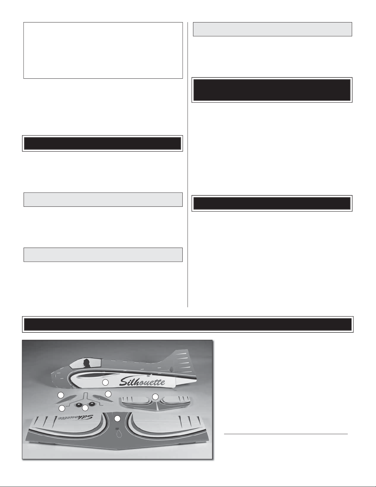
KIT INSPECTION
Before starting to build, take an inventory of this kit
to make sure it is complete, and inspect the parts
to make sure they are of acceptable quality. If any
parts are missing or are not of acceptable quality,
or if you need assistance with assembly, contact
1
5
6
4
5
2
3
3
Product Support.
Great Planes Product Support
3002 N Apollo Drive, Suite 1
Champaign, IL 61822
Telephone: (217) 398-8970, ext. 5
Fax: (217) 398-7721
E-mail: airsupport@greatplanes.com
1. Fuselage
2. Wing
3. Horizontal Stab
4. Wheels (2)
5. Wheel Pants (2)
6. Main Landing Gear
Page 4
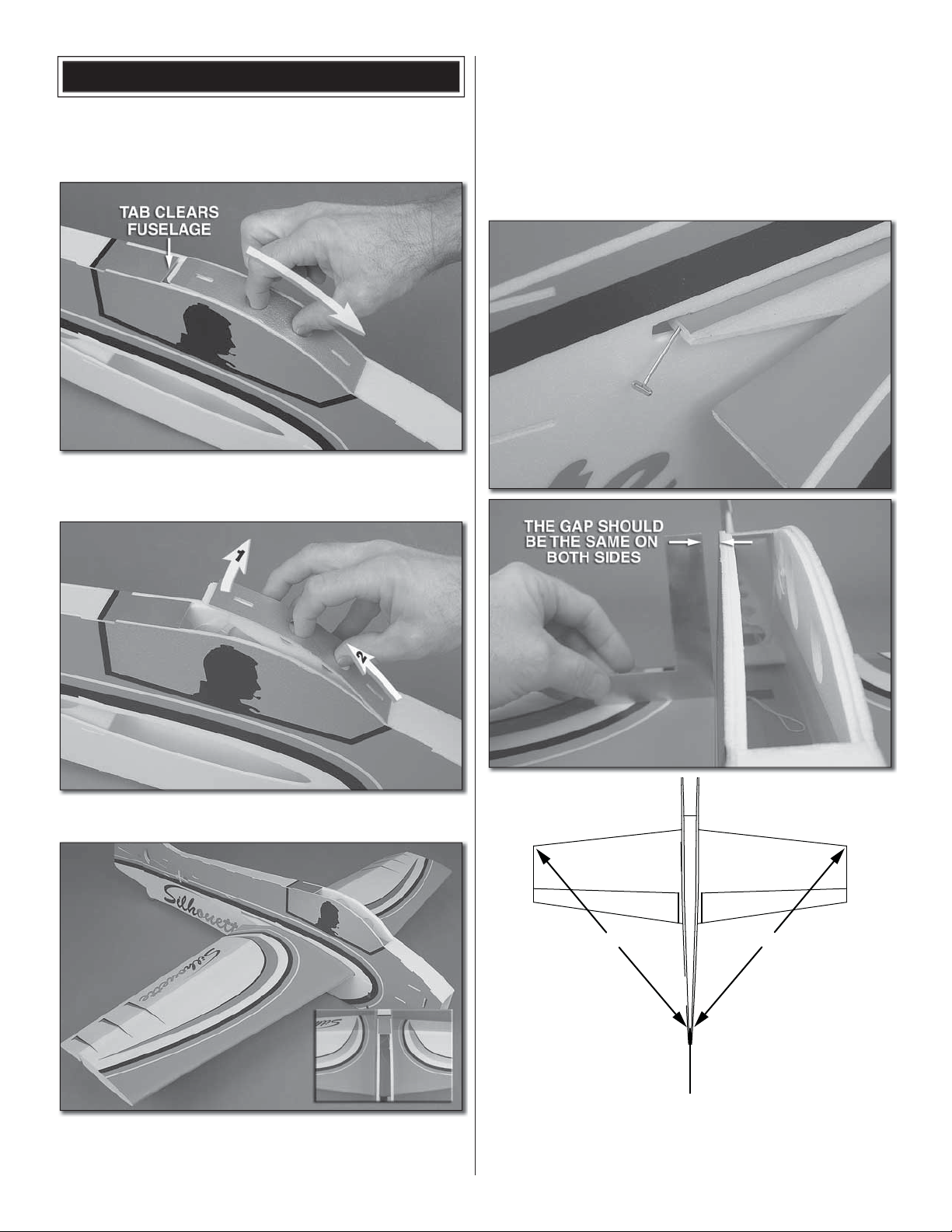
INSTALL THE WING
Due to the radius of the leading edge of the wing and the material
used in construction of the wing, small cracks are not uncommon
and will not cause any undesirable fl ight characteristics.
❏ 1. Remove the battery hatch (canopy top) by carefully sliding
it forward until the tab at the aft end clears the fuselage top.
fuselage. If the wing is tight when sliding through the fuselage,
you may have to carefully work it back and forth. If it is still
too tight, lightly sanding the opening may be required. The
reason the wing slides in tightly is that the wing is tapered
and the center of the wing is slightly larger than the section
that is glued to the fuselage. So, do not sand the opening
too much or the wing will fi t loosely in the fuselage, requiring
excessive CA to fi ll the gap.
❏ 2. Then lift the battery hatch up and slide it out at the front.
❏ 3. Carefully insert the wing in the fuselage so that the
aileron servo openings are on the bottom. Make sure the
string coming out of the center of the wing is inside the
AA'
A = A'
❏ 4. Slide the wing forward and center the wing in the fuselage.
Measure the distance from the wing tips to the center of the
top of the fi n. Adjust the wing so that the distance is the
same. T-pins can be inserted in the trailing edge to help hold
4
Page 5
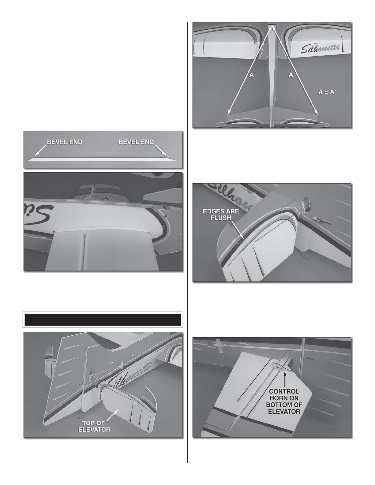
the wing in position. Use a square to check that the wing is
perpendicular to the fuselage. Since the fuselage is tapered,
make sure the gap is the same on both sides.
❏ 5. With the plane setting on your building table, apply a
bead of foam-safe thin CA along the top joint between the
fuselage and the wing. Once the CA has cured (do not use
CA activator yet), turn the plane over and again apply a bead
of foam-safe thin CA along the bottom joint.
❏ 6. Once the foam-safe thin CA has cured, apply a bead of
foam-safe medium CA along the joint where there is a gap
between the fuselage and the wing. Now use foam-safe CA
activator on the glue joints.
❏ 2. Insert the stab in the stab slot and center it side-to-side.
Measure the distance from the tip of the stab to the center
of the fuselage. Adjust the position of the stab until they are
equal. Also check that the stab is parallel with the wing when
viewed from the aft end. Use thin foam-safe CA to glue the
stab to the fuselage.
❏ 7. Bevel the ends of the two 3mm x 6mm x 290mm wing
reinforcement strips. Glue the strips to the underside of the
wing and fuselage joint.
INSTALL THE STABILIZER
❏ 1. Carefully insert the elevator in the stabilizer slot. Make
sure the counter balances are facing forward and the correct
side is up.
❏ 3. Cut two 170mm long pieces of clear tape for the elevator
hinges. Apply one of the pieces of tape to the leading edge of
the left elevator half so that half of the tape is on the elevator.
Center the elevator on the stabilizer and with the elevator
hanging down, press the hinge tape onto the stabilizer.
Repeat the process on the right side.
❏ 4. Insert one of the plywood control horns in the slot in the
bottom of the elevator. Glue the control horn in the elevator
with foam-safe thin CA.
5
Page 6

❏ ❏ 2. From the battery compartment, carefully pull the
aileron lead through the wing and out the opening in the
center of the wing.
❏ ❏ 3. Use medium foam-safe CA to glue the aileron servo
in the aileron servo tray.
❏ 4. Follow the same procedure to install the second aileron
servo in the other wing half.
❏ 5. Trial fi t the remaining two plywood control horns in the
bottom of the ailerons. You may need to use a sharp hobby
knife to open the front of the slot to allow the control horns
to seat against the bottom of the aileron. Use foam-safe thin
CA to glue the control horns in the ailerons.
RADIO INSTALLATION
❏ 5. Use a Y-harness to connect the two aileron servos.
Connect the Y-harness to your receiver. A separate receiver
battery or the ESC can be connected to the receiver to power
the servos for set up.
❏ 6. Switch on your transmitter and center the aileron
servo trim.
❏ ❏ 1. Install a 12" [304mm] servo extension on each aileron
servo. A piece of electrical tape can be used to secure the
extension to the aileron servo lead. Tie the string from one
of the aileron servo trays to the end of the aileron servo lead
extension. Then use a piece of masking tape to secure the
string out the end of the connector.
❏ ❏ 7. Install a servo arm that has a hole approximately
5/8" [16mm] from the center. Enlarge the hole with a #55
(3/64") drill bit. Insert the brass quick connector in the hole
and secure it with a nylon keeper.
6
Page 7

❏ ❏ 8. Install the servo arm on the servo. Insert the Z-bend
end of a 3-3/8" [86mm] pushrod in the lower hole in the
aileron control horn. Insert the other end of the pushrod in
the quick connector. Install a 2 x 4mm machine screw in the
quick connector. Center the aileron and tighten the machine
screw on the pushrod. Trim the excess wire 1/4" [6mm] from
the quick connector.
❏ 12. Connect the elevator servo to the receiver and center
the servo arm on the servo. Install the 6-1/4" [159mm] pushrod
in the outer hole of the rudder control horn. Follow the same
method to complete the installation as before except install
the brass quick connector in the hole 1/2" [13mm] from the
center of the rudder servo arm.
❏ 9. Return to step 7 and install the pushrod on the
other aileron.
❏ 10. Install the rudder and elevator servos in the servo
cutouts in the aft end of the fuselage.
INSTALL THE MAIN LANDING GEAR
❏ 1. Insert the main landing gear wire in the landing gear slot.
❏ 11. Connect the rudder servo to the receiver and center
the servo arm on the servo. Install the 8-3/16" [208mm]
pushrod in the outer hole of the rudder control horn. Follow
the same method to complete the installation as used for the
ailerons except install the brass quick connector in the hole
7/16" [11mm] from the center of the rudder servo arm.
❏ 2. Insert the plywood landing gear retainer in the landing gear
slot. The rounded corners are inserted fi rst. If it fi ts loosely, use
a piece of tape (not included) to hold the retainer in position.
7
Page 8

❏ 3. Slide a wheel onto the main landing gear wire. Insert
the wheel pant on the wire and apply a drop of foam-safe thin
CA to the wheel pant to secure it to the wire. Make sure to
not glue the wheel to the wire.
❏ 4. Install the other wheel and wheel pant on the main
landing gear.
MOTOR INSTALLATION
❏ 2. Attach a piece of hook and loop material to the back of
the SS-12 brushless ESC. Route the motor wires through the
hole in the landing gear mount slot and connect the motor
wires to the motor. Route the battery and receiver plug up
through the opening in front of the wing. Attach an opposite
piece of hook and loop material to the bottom of the wing.
Attach the ESC to the hook and loop material on the bottom
of the wing.
❏ 3. Plug the ESC into the receiver. Use hook and loop
material to attach the receiver to the top of the wing, inside
the fuselage.
❏ 1. Position the RimFire 400 (28-30-950kV) brushless
motor on the motor mount with the wires down. Use the three
3 x 10mm sheet metal screws to mount the motor to the
motor mount. After tightening the screws, remove the screws
and motor and apply a couple of drops of thin CA to the
threads to harden the wood. After the CA has cured, reinstall
the motor.
❏ 4. Before installing the propeller, temporarily plug the
motor battery into the ESC and check to see if the motor is
rotating in the correct direction.
8
Page 9

GET THE MODEL READY TO FLY
Set the Control Throws
Check the Control Directions
❏ 1. Turn on the transmitter and receiver and center the
trims. If necessary, remove the servo arms from the servos
and reposition them so they are centered. Reinstall the
screws that hold on the servo arms.
❏ 2. With the transmitter and receiver still on, check all the
control surfaces to see if they are centered. If necessary,
loosen the screw in the quick connector and center the
control surfaces.
4-CHANNEL RADIO SET UP
(STANDARD MODE 2)
RIGHT AILERON
RUDDER
MOVES
RIGHT
MOVES UP
LEFT AILERON
MOVES DOWN
To ensure a successful fi rst fl ight, set up your Silhouette
3D ARF according to the control throws specifi ed in this
manual. The throws have been determined through actual
fl ight testing and accurate record-keeping allowing the
model to perform in the manner in which it was intended.
If, after you have become accustomed to the way the
Silhouette 3D ARF fl ies, you would like to change the throws
to suit your taste, that is fi ne. However, too much control
throw could make the model too responsive and diffi cult to
control, so remember, “more is not always better.”
❏ 1. Use a box or something similar to prop up the bottom of
the fuselage so the horizontal stabilizer and wing will be level.
FULL
THROTTLE
ELEVATOR
MOVES DOWN
❏ 3. Make certain that the control surfaces respond in
the correct direction as shown in the diagram. If any of
the controls respond in the wrong direction, use the servo
reversing in the transmitter to reverse the servos connected
to those controls. Be certain the control surfaces have
remained centered. Adjust if necessary.
❏ 2. Measure the 3D elevator throw fi rst. Hold a ruler vertically
on your workbench against the widest part (front to back) of
the trailing edge of the elevator. Note the measurement on
the ruler.
❏ 3. Move the elevator up with your transmitter and move the
ruler forward so it will remain contacting the trailing edge. The
distance the elevator moves up from center is the “up” elevator
throw. Measure the down elevator throw the same way.
❏ 4. Measure and set the low rate elevator throws and the
high and low rate throws for the rest of the control surfaces
the same way.
9
Page 10

NOTE: The throws are measured at the widest part of the
elevators, rudder and ailerons. If your radio does not have
dual rates, we recommend setting the throws at the high
rate settings.
from the fuselage sides, on both sides of the fuselage 4"
[102mm] back from the leading edge. Apply narrow (1/16"
[2mm]) strips of tape over the lines so you will be able to feel
them when lifting the model with your fi ngers.
These are the recommended control surface throws:
LOW RATE
Up
1"
[
25mm
]
17°
Right
2-3/8"
[
60mm
]
24°
Up
3/4"
[19mm]
12°
Down
1"
]
[
25mm
17°
Left
2-3/8"
]
[
60mm
24°
Down
3/4"
[19mm]
12°
ELEVATOR
RUDDER
AILERONS
3D RATE
Up
1-3/4"
[44mm]
31°
Right
4-1/2"
[
114mm
52°
Up
1-1/4"
[
32mm
20°
Down
1-3/4"
[44mm]
31°
Left
4-1/2"
]
[
114mm
52°
Down
1-1/4"
]
[
32mm
20°
HIGH RATE
Up
1-3/8"
[
35mm
24°
Right
3-1/2"
[
]
89mm
37°
Up
1"
[25mm]
]
16°
Down
1-3/8"
]
[
35mm
24°
Left
3-1/2"
]
[
89mm
37°
Down
1"
[25mm]
16°
Balance the Model (C.G.)
This is where your model should balance for the fi rst
fl ights. Later, you may experiment by shifting the C.G. 3/8”
[9.5mm] forward or 1/4” [6mm] back to change the fl ying
characteristics. Moving the C.G. forward will improve the
smoothness and stability, but the model will then be less
aerobatic (which may be fi ne for less-experienced pilots).
Moving the C.G. aft makes the model more maneuverable
and aerobatic for experienced pilots. In any case, start at
]
the recommended balance point and do not at any time
balance the model outside the specifi ed range.
]
More than any other factor, the C.G. (center of gravity/
balance point) can have the greatest effect on how a
model fl ies and could determine whether or not your fi rst
fl ight will be successful. If you value your model and wish
to enjoy it for many fl ights, DO NOT OVERLOOK THIS
IMPORTANT PROCEDURE. A model that is not properly
balanced may be unstable and possibly unfl yable.
Now is the time to install the propeller. At this stage the model
should be in ready-to-fl y condition with all of the components
in place including the complete radio system. The motor
battery has not been installed yet. You will move the motor
battery forward and aft to balance the plane.
❏ 2. With the wing attached to the fuselage, all parts of the
model installed (ready to fl y), place the model upside-down
on a Great Planes CG Machine, or lift it upside down at the
balance point you marked. Place the motor battery on the
bottom of the fuselage.
❏ 1. If using a Great Planes C.G. Machine
to 4" [102mm]. If not using a C.G. Machine, use a fi ne-point
felt tip pen to mark lines on the top of wing, 1" [25mm] out
™
, set the rulers
❏ 3. If the tail drops, the model is “tail heavy.” Move the motor
battery forward to get the model to balance. If the nose drops,
the model is “nose heavy.” Move the motor battery aft. Once
you have determined the battery location required to balance
the plane note the location and where the battery would need
to be attached inside the fuselage, above the wing.
10
Page 11

❏ 4. Apply the remaining hook and loop material to the
inside of the fuselage at the approximate location for the
motor battery. The closer to the top of the wing the better.
Attach an opposite piece of hook and loop material to the
battery. Trial fi t the motor battery in the fuselage and recheck
the CG. Once you have determined the correct location for
the motor battery, mark the location with a fi ne tip marker.
CAUTION: Unless the instructions that came with your
radio system state differently, the initial charge on new
transmitter batteries should be done for 15 hours using
the slow-charger that came with the radio system.
This will “condition” the batteries so that the next charge
may be done using the fast-charger of your choice. If the
initial charge is done with a fast-charger the batteries may
not reach their full capacity and you may be fl ying with
batteries that are only partially charged.
Balance Propellers
Balance the Model Laterally
❏ 1. With the wing level, have an assistant help you lift the
model by the motor propeller shaft and the bottom of the
fuse under the TE of the fi n. Do this several times.
❏ 2. If one wing always drops when you lift the model, it means
that side is heavy. Balance the airplane by adding weight
to the other wing tip. An airplane that has been laterally
balanced will track better in loops and other maneuvers.
PREFLIGHT
Identify Your Model
No matter if you fl y at an AMA sanctioned R/C club site or
if you fl y somewhere on your own, you should always have
your name, address, telephone number and AMA number on
or inside your model. It is required at all AMA R/C club fl ying
sites and AMA sanctioned fl ying events (except when fl own
indoors). Fill out the identifi cation tag on page 15 and place
it on or inside your model.
Charge the Batteries
Carefully balance your propeller and spare propellers before
you fl y. An unbalanced prop can be the single most signifi cant
cause of vibration that can damage your model. Vibration
of props on small models can cause a loss of power, but
vibration may also damage your radio receiver, battery and
possibly the motor bearings.
We use a Top Flite® Precision Magnetic Prop Balancer
(TOPQ5700) in the workshop and keep a Great Planes
Fingertip Prop Balancer (GPMQ5000) in our fl ight box.
Ground Check and Range Check
Always ground check the operational range of your radio
before the fi rst fl ight of the day following the manufacturer’s
instructions that came with your radio. This should be done
once with the motor off and once with the motor running
at various speeds. If the control surfaces do not respond
correctly, do not fl y! Find and correct the problem fi rst. Look
for loose servo connections or broken wires, corroded wires
on old servo connectors, poor solder joints in your battery
pack or a defective cell, or a damaged receiver crystal from
a previous crash.
Follow the battery charging instructions that came with your
radio control system to charge the batteries. You should
always charge your transmitter batteries the night before
you go fl ying, and at other times as recommended by the
radio manufacturer.
11
Page 12

MOTOR AND BATTERY SAFETY
Radio Control
Failure to follow these safety precautions may result
in severe injury to yourself and others.
• Do not run the motor in an area of loose gravel or sand; the
propeller may throw such material in your face or eyes.
• Keep your face and body as well as all spectators away
from the plane of rotation of the propeller as you start and
run the motor.
• Keep these items away from the prop: loose clothing, shirt
sleeves, ties, scarfs, long hair or loose objects such as
pencils or screwdrivers that may fall out of shirt or jacket
pockets into the prop.
• The motor can get hot! Do not touch it right after operation.
• Once the motor battery is plugged in to the ESC, stay clear
of the propeller. The motor could start at any time.
• Do not charge the LiPo motor battery in the plane.
• Never leave a LiPo battery unattended while charging.
• If your plane is in a hard crash, remove the LiPo battery and
set it aside in a safe location for at least 20 minutes. If the
battery is damaged in the crash it could catch fi re.
1) I will have completed a successful radio equipment ground
check before the fi rst fl ight of a new or repaired model.
2) I will not fl y my model aircraft in the presence of spectators
until I become a qualifi ed fl ier, unless assisted by an
experienced helper.
3) At all fl ying sites a straight or curved line(s) must be
established in front of which all fl ying takes place with the
other side for spectators. Only personnel involved with
fl ying the aircraft are allowed at or in the front of the fl ight
line. Intentional fl ying behind the fl ight line is prohibited.
4) I will operate my model using only radio control frequencies
currently allowed by the Federal Communications Commission.
5) I will not knowingly operate my model within three miles of
any pre-existing fl ying site except in accordance with the
frequency sharing agreement listed [in the complete AMA
Safety Code].
9) Under no circumstances may a pilot or other person touch
a powered model in fl ight; nor should any part of the
model other than the landing gear, intentionally touch the
ground, except while landing.
CHECK LIST
• If the battery starts to swell, quickly move the battery to a
safe location, preferably outside and place it in a bucket
covering the battery with sand.
AMA SAFETY CODE (EXCERPTS)
Read and abide by the following excerpts from the Academy
of Model Aeronautics Safety Code. For the complete Safety
Code refer to Model Aviation magazine, the AMA web site or
the Code that came with your AMA license.
General
1) I will not fl y my model aircraft in sanctioned events,
air shows, or model fl ying demonstrations until it has
been proven to be airworthy by having been previously,
successfully fl ight tested.
2) I will not fl y my model aircraft higher than approximately
400 feet within 3 miles of an airport without notifying the
airport operator. I will give right-of-way and avoid fl ying
in the proximity of full-scale aircraft. Where necessary,
an observer shall be utilized to supervise fl ying to avoid
having models fl y in the proximity of full-scale aircraft.
3) Where established, I will abide by the safety rules for the
fl ying site I use, and I will not willfully and deliberately fl y my
models in a careless, reckless and/or dangerous manner.
5) I will not fl y my model unless it is identifi ed with my name
and address or AMA number, on or in the model. Note:
This does not apply to models while being fl own indoors.
7) I will not operate models with pyrotechnics (any device
that explodes, burns, or propels a projectile of any kind).
During the last few moments of preparation your mind
may be elsewhere anticipating the excitement of the fi rst
fl ight. Because of this, you may be more likely to overlook
certain checks and procedures that should be performed
before the model is fl own. To help avoid this, a check list
is provided to make sure these important areas are not
overlooked. Many are covered previously in the instruction
manual, so where appropriate, refer to the manual for
complete instructions. Be sure to check the items off as
they are completed.
❏ 1. Check the C.G. according to the measurements
provided in the manual.
❏ 2. Be certain the battery and receiver are securely
mounted in the fuse with hook and loop material.
❏ 3. Balance your model laterally as explained in
the instructions.
❏ 4. Use threadlocking compound to secure critical
fasteners such as the screws that hold the screw-lock
pushrod connectors.
❏ 5. Add a drop of oil to the axles so the wheels will
turn freely.
❏ 6. Reinforce holes for wood screws with thin CA where
appropriate such as the motor mounting screws.
❏ 7. Confi rm that all controls operate in the correct direction
and the throws are set up according to the manual.
❏ 8. Make sure all servo arms are secured to the servos
with the screws included with your radio.
❏ 9. Balance your propeller (and spare propellers).
❏ 10. Tighten the propeller nut and spinner.
❏ 11. If you wish to photograph your model, do so before
your fi rst fl ight.
❏ 12. Range check your radio when you get to the fl ying fi eld.
12
Page 13

FLYING
Landing
CAUTION (THIS APPLIES TO ALL R/C AIRPLANES): If,
while fl ying, you notice an alarming or unusual sound such
as a low-pitched “buzz,” this may indicate control surface
fl utter. Flutter occurs when a control surface (such as an
aileron or elevator) or a fl ying surface (such as a wing or
stab) rapidly vibrates up and down (thus causing the noise).
In extreme cases, if not detected immediately, fl utter can
actually cause the control surface to detach or the fl ying
surface to fail, thus causing loss of control followed by
an impending crash. The best thing to do when fl utter is
detected is to slow the model immediately by reducing
power, then land as soon as safely possible. Identify which
surface fl uttered. Make certain all pushrod linkages are
secure and free of play. If it fl uttered once, under similar
circumstances it will probably fl utter again unless the
problem is fi xed. Some things which can cause fl utter
are; Excessive hinge gap; Not mounting control horns
solidly; Excessive free play in servo gears; Insecure servo
mounting; and one of the most prevalent causes of fl utter;
Flying an over-powered model at excessive speeds.
Takeoff
The Silhouette 3D ARF can take off from a smooth surface or
can be easily hand launched. If for the fi rst fl ight the plane is to
be hand launched, have an assistant hand launch it. This will
allow you, the pilot, to have both hands on the control sticks
to make any fl ight corrections if the plane is out of trim. Once
the Silhouette 3D ARF has been fl own and trimmed out, you
will be able to hand launch the plane easily by yourself. If you
are fl ying outdoors, always take off into the wind.
To initiate a landing approach, lower the throttle while on the
downwind leg. Allow the nose of the model to pitch downward
to gradually bleed off altitude. Continue to lose altitude, but
maintain airspeed by keeping the nose down as you turn onto
the crosswind leg. Make your fi nal turn toward the landing
area, keeping the nose down to maintain airspeed and
control. Level the attitude when the model reaches the edge
of the landing area, modulating the throttle as necessary to
maintain your glide path and airspeed. If you are going to
overshoot, smoothly advance the throttle (always ready on
the right rudder to counteract torque) and climb out to make
another attempt. When you’re ready to make your landing
fl are and the model is a foot or so off the deck, smoothly
increase up elevator until it gently touches down.
One fi nal note about fl ying your model. Have a goal or fl ight
plan in mind for every fl ight. This can be learning a new
maneuver(s), improving a maneuver(s) you already know,
or learning how the model behaves in certain conditions
(such as on high or low rates). This is not necessarily to
improve your skills (though it is never a bad idea!), but more
importantly so you do not surprise yourself by impulsively
attempting a maneuver and suddenly fi nding that you’ve run
out of time, altitude or airspeed. Every maneuver should be
deliberate, not impulsive. For example, if you’re going to do
a loop, check your altitude, remember to throttle back at the
top, and make certain you are on the desired rates (high/low
rates). A fl ight plan greatly reduces the chances of crashing
your model just because of poor planning and impulsive
moves. Remember to think.
Have a ball!
But always stay in control and fl y in a safe manner.
GOOD LUCK AND GREAT FLYING!
Flight
For reassurance and to keep an eye on other traffi c, it is a
good idea to have an assistant on the fl ight line with you. While
full throttle is usually desirable for takeoff, the Silhouette 3D
ARF will fl y great at ½ to ¼ throttle indoors.
Take it easy with the Silhouette 3D ARF for the fi rst few fl ights,
gradually getting acquainted with it as you gain confi dence.
Adjust the trims to maintain straight and level fl ight. After
fl ying around for a while, and while still at a safe altitude with
plenty of battery power left, practice slow fl ight and execute
practice landing approaches by reducing the throttle to see
how the model handles at slower speeds. Add power to see
how she climbs as well. Continue to fl y around, executing
various maneuvers and making mental notes (or having your
assistant write them down) of what trim or C.G. changes may
be required to fi ne tune the model so it fl ies the way you like.
Mind your battery power. It is best to have a timer set to alert
you when it is time to land.
13
Page 14

ALSO AVAILABLE FROM GREAT PLANES
Wingspan: 32.5 in (830 mm)
Wing Area: 518 in² (33.4 dm²)
Weight: 8.4–9.5 oz (240-270 g)
Wing Loading: 2.3 - 2.6 oz/ft² (7.2-8.1 g/dm²)
Length: 38 in (955 mm)
Requires: 4-channel radio w/3 micro servos,
out-runner brushless motor,
8A brushless ESC (min)
& 11.1V 300mAh LiPo battery
The Pluma takes foam construction to a new dimension, with a full fuselage that’s more realistic-looking than fl at foamies AND stronger
by design, without carbon reinforcing. With the trim scheme imprinted and all other parts laser-cut and interlocking, the Pluma can be
fl ight-ready in about an hour. Control surfaces are already beveled and hinged with ultra-light 3M® Blenderm® tape. Even the smallest of
RimFire™ out-runner brushless motors will effi ciently power the Pluma, and it’s sized right for easy transport to the fi eld or an indoor dome.
GPMA1130
3M® and Blenderm® are registered trademarks of the Minnesota Mining and Manufacturing Company.
™
Wingspan: 32 in (820 mm)
Wing Area: 270 in² (17.4 dm²)
Weight Range: 5.5-6.7 oz (155-190 g)
Wing Loading: 2.9-3.5 oz/ft² (9-11 g/dm²)
Length: 36.5 in (920 mm)
Requires: 4-channel radio w/3 micro servos,
out-runner brushless motor,
8A brushless ESC,
7.4V 300mAh LiPo battery
When ElectriFly calls this an “unlimited” foam aerobat,
they’re talking about performance. It’s a great sport model with ¾ throws. Max
‘em, and you’ll fi nd a performance envelope that’s wide open and a mile long. Assembly time averages about 2-3 hours. All control surfaces
are factory-beveled and pre-hinged with proven 3M® Blenderm® tape. Flying surfaces are fi nished and made from Pro-Formance foam.
Total weight is under 7 ounces, and also minimized by carbon-fi ber and laser-cut hardware. As always, less weight = more performance!
GPMA1131
3M® and Blenderm® are registered trademarks of the Minnesota Mining and Manufacturing Company.
14
Page 15

™
Wingspan: 41 in (1040 mm)
Wing Area: 343 in² (22.1 dm²)
Weight: 27.5 – 31 oz (780-880 g)
Wing Loading: 11.5 – 13 oz/ft² (35-40 g/dm²)
Length: 38 in (965 mm)
Requires: 4-5 channel radio w/4 micro servos,
1250kV out-runner brushless motor, 35A
brushless ESC (min.) & 11.1V 1500mAh
LiPo battery
The SU-31’s cutting-edge maneuvers and astounding aerobatics have made it an air show superstar for almost two decades. An eyecatching MonoKote trim scheme and compact size are sure to do the same for this E-Performance Series ARF. Take it out for a fun day of
sport fl ying or perform pulse-quickening 3D maneuvers! It’s compact and easy to take along to the fl ying fi eld or the local park. The model
combines traditional, built-up construction with the benefi ts of brushless power. Wing halves slide onto a carbon-fi ber wing tube for fast
assembly and accurate alignment. GPMA1547
Wingspan: 50 in (1270 mm)
Wing Area: 494 in² (31.9 dm²)
Weight: 3.25-3.5 lb (1475-1590 g)
Wing Loading: 15-16 oz/ft² (46-49 g/dm²)
Length: 47.75 in (1215 mm)
Requires: 4-channel radio w/4 micro servos, receiver,
45A ESC,
out-runner brushless motor,
11.1V 2100mAh LiPo battery
Acclaimed aviator Matt Chapman is famous for thrilling crowds with his jaw-dropping
aerobatics at air shows worldwide. Now you can impress your friends at your local fl ying fi eld
with this offi cially licensed, 50” span reproduction of his Eagle 580! Its ultra-light airframe
and airfoiled control surfaces offer precision tracking and incredible agility. State-of-theart materials – including carbon fi ber, hand-selected woods and fi berglass – accelerate
assembly time to just 6-8 hours. A factory-applied MonoKote® trim scheme adds eyecatching looks, while die-cut decals let you recreate Matt Chapman’s Embry-Riddle-inspired
design – or create a custom look of your own. GPMA1573
15
Make a copy of this identifi cation tag
and put it on or inside your model.
Page 16

 Loading...