

Great Planes GPMA1127 User Manual
INSTRUCTION
MANUAL
SPECIFICATIONS
Wingspan:
Wing Area: 243 in
33 in
[840 mm]
2
[15.7 dm2]
WARRANTY
Great Planes® Model Manufacturing Co. guarantees this kit to
be free from defects in both material and workmanship at the
date of purchase. This warranty does not cover any component
parts damaged by use or modification. In no case shall Great
Planes’ liability exceed the original cost of the purchased kit.
Further, Great Planes reserves the right to change or modify this
warranty without notice.
In that Great Planes has no control over the final assembly or
material used for final assembly, no liability shall be assumed nor
accepted for any damage resulting from the use by the user of
the final user-assembled product. By the act of using the
user-assembled product, the user accepts all resulting liability.
If the buyer is not prepared to accept the liability associated
with the use of this product, the buyer is advised to return
Weight:
Wing
Loading:
6.0 – 6.3 oz
[170 –180 g]
3.6 – 3.7 oz/ ft
[11 g/dm2]
®
Length: 29.5 in [750 mm]
Radio: 4- channel
2
this kit immediately in new and unused condition to the
place of purchase.
To make a warranty claim send the defective part or item to
Hobby Services at the address below:
Include a letter stating your name, return shipping address, as
much contact information as possible (daytime telephone
number, fax number, e-mail address), a detailed description of
the problem and a photocopy of the purchase receipt. Upon
receipt of the package the problem will be evaluated as quickly
as possible.
Motor: RimFire
outrunner brushless motor
Hobby Services
3002 N. Apollo Dr. Suite 1
Champaign IL 61822 USA
™
250
READ THROUGH THIS MANUAL BEFORE STARTING CONSTRUCTION. IT CONTAINS IMPORTANT
INSTRUCTIONS AND WARNINGS CONCERNING THE ASSEMBLY AND USE OF THIS MODEL.
Entire Contents © 2011 Hobbico,® Inc. All rights reserved.
Champaign, Illinois
(217) 398-8970, Ext 5
airsupport@greatplanes.com
GPMA1127 Mnl

TABLE OF CONTENTS
INTRODUCTION . . . . . . . . . . . . . . . . . . . . . . . . . . . . . . . . 2
Academy of Model Aeronautics . . . . . . . . . . . . . . . . . . 2
SAFETY PRECAUTIONS . . . . . . . . . . . . . . . . . . . . . . . . . 2
DECISIONS YOU MUST MAKE. . . . . . . . . . . . . . . . . . . . . 3
Indoor Motor & Battery Recommendations . . . . . . . . . 3
Radio Recommendations. . . . . . . . . . . . . . . . . . . . . . . 3
Charger . . . . . . . . . . . . . . . . . . . . . . . . . . . . . . . . . . . .3
ADDITIONAL ITEMS REQUIRED . . . . . . . . . . . . . . . . . . .3
Adhesives and Building Supplies. . . . . . . . . . . . . . . . . 3
Optional Supplies. . . . . . . . . . . . . . . . . . . . . . . . . . . . . 4
IMPORTANT BUILDING NOTES. . . . . . . . . . . . . . . . . . . . 4
KIT INSPECTION. . . . . . . . . . . . . . . . . . . . . . . . . . . . . . . . 4
KIT CONTENTS. . . . . . . . . . . . . . . . . . . . . . . . . . . . . . . . . 4
BUILD THE FUSELAGE . . . . . . . . . . . . . . . . . . . . . . . . . . 5
Assemble the Fuselage . . . . . . . . . . . . . . . . . . . . . . . . 5
Install the Wing Supports . . . . . . . . . . . . . . . . . . . . . . . 6
Install the Fuselage Doublers. . . . . . . . . . . . . . . . . . . .9
RADIO INSTALLATION. . . . . . . . . . . . . . . . . . . . . . . . . . . 9
Install the Rudder & Elevator Servos . . . . . . . . . . . . . . 9
Adjust the Pushrods. . . . . . . . . . . . . . . . . . . . . . . . . . 11
Install the Aileron Servo . . . . . . . . . . . . . . . . . . . . . . . 12
INTRODUCTION
If you’ve built any of the previous Great Planes Indoor Aerobatic
planes, the Citabria 3D Indoor EP ARF uses the same proven
methods. If this is your fi rst Great Planes Indoor Aerobatic
plane, you will be surprised at how quickly and easily you can
have it in the air. The building crutches make aligning the parts
a non-issue. So let’s get this plane built and go have some fun.
INST ALL THE MOTOR. . . . . . . . . . . . . . . . . . . . . . . . . . .13
BALANCE THE MODEL (C.G.). . . . . . . . . . . . . . . . . . . . 14
GET THE MODEL READY TO FLY . . . . . . . . . . . . . . . . . 15
Check the Control Directions . . . . . . . . . . . . . . . . . . . 15
Set the Control Throws. . . . . . . . . . . . . . . . . . . . . . . . 15
PREFLIGHT. . . . . . . . . . . . . . . . . . . . . . . . . . . . . . . . . . . 16
Identify Your Model. . . . . . . . . . . . . . . . . . . . . . . . . . . 16
Charge the Batteries . . . . . . . . . . . . . . . . . . . . . . . . .16
Balance Propellers. . . . . . . . . . . . . . . . . . . . . . . . . . . 16
Ground Check and Range Check . . . . . . . . . . . . . . .16
MOTOR & BATTERY SAFETY PRECAUTIONS. . . . . . . 16
LITHIUM BATTERY HANDLING & USAGE . . . . . . . . . . 17
AMA SAFETY CODE. . . . . . . . . . . . . . . . . . . . . . . . . . . . 17
General . . . . . . . . . . . . . . . . . . . . . . . . . . . . . . . . . . . 17
Radio Control . . . . . . . . . . . . . . . . . . . . . . . . . . . . . . . 17
CHECK LIST . . . . . . . . . . . . . . . . . . . . . . . . . . . . . . . . . . 17
FLYING. . . . . . . . . . . . . . . . . . . . . . . . . . . . . . . . . . . . . . . 18
Takeoff . . . . . . . . . . . . . . . . . . . . . . . . . . . . . . . . . . . . 18
Flight . . . . . . . . . . . . . . . . . . . . . . . . . . . . . . . . . . . . . 18
Landing . . . . . . . . . . . . . . . . . . . . . . . . . . . . . . . . . . . 18
Or via the Internet at:
http://www.modelaircraft.org
http://www.modelaircraft.org/parkfl yer.aspx
IMPORTANT!!! Two of the most important things you can
do to preserve the radio controlled aircraft hobby are to avoid
fl ying near full-scale aircraft and avoid fl ying near or over
groups of people.
For the latest technical updates or manual corrections to the
Citabria 3D Indoor EP ARF, visit the Great Planes web site
at www.greatplanes.com. Open the “Airplanes” link, then
select the Citabria 3D Indoor EP ARF. If there is new technical
information or changes to this model a “tech notice” box will
appear in the upper left corner of the page.
Academy of Model Aeronautics
If you are not already a member of the AMA, please join! The
AMA is the governing body of model aviation and membership
provides liability insurance coverage, protects modelers’ rights
and interests and is required to fl y at most R/C sites. The AMA
has two classes of membership available: Open membership
or their Park Pilot Program, which this aircraft qualifi es for. The
Park Pilot Program is for people fl ying electric aircraft and
gliders under two pounds and which fl y slower than 60mph.
This will enable you to enjoy most AMA benefi ts and organize
clubs and fl ying sites in more congested areas.
Academy of Model Aeronautics
5151 East Memorial Drive
Muncie, IN 47302-9252
Ph. (800) 435-9262
Fax (765) 741-0057
SAFETY PRE CAUTION S
Protect Your Model, Yourself & Others …
Follow These Important Safety Precautions
1. Your Citabria 3D Indoor EP ARF should not be considered
a toy, but rather a sophisticated, working model that
functions very much like a full-size airplane. Because of its
performance capabilities, the Citabria 3D, if not assembled
and operated correctly, could possibly cause injury to
yourself or spectators and damage to property.
2. You must assemble the model according to the
instructions. Do not alter or modify the model, as doing
so may result in an unsafe or unfl yable model. In a few
cases the instructions may differ slightly from the photos.
In those instances the written instructions should be
considered as correct.
3. You must take time to build straight, true and strong.
4. You must use an R/C radio system that is in good condition,
a correctly sized engine, and other components as specifi ed
in this instruction manual. All components must be correctly
installed so that the model operates correctly on the ground
and in the air. You must check the operation of the model
and all components before every fl ight.
2

5. If you are not an experienced pilot or have not fl own this
type of model before, we recommend that you get the
assistance of an experienced pilot in your R/C club for
your fi rst fl ights. If you’re not a member of a club, your
local hobby shop has information about clubs in your area
whose membership includes experienced pilots.
6. Carefully read and follow all the instructions included with
your LiPo battery and battery charger. LiPo batteries are
not forgiving like NiCd or NiMH batteries. Overcharging or
charging the LiPo battery at too high a current will damage
the battery and could damage property.
We, as the kit manufacturer, provide you with a top quality,
thoroughly tested kit and instructions, but ultimately the
quality and fl yability of your fi nished model depends
on how you build it; therefore, we cannot in any way
guarantee the performance of your completed model,
and no representations are expressed or implied as to
the performance or safety of your completed model.
Remember: Take your time and follow the instructions to
end up with a well-built model that is straight and true.
DECISI ONS YOU MUST MAKE
This is a partial list of items required to fi nish the Citabria
3D Indoor EP ARF that may require planning or decision
making before starting to build. Order numbers are provided
in parentheses.
Indoor Motor and
Battery Recommendations
For best indoor fl ight performance, a lightweight battery is
recommended. We recommend:
(1) Great Planes
❍
20C LiPo battery (GPMP0700)
(1) FlightPower
❍
LiPo battery (FPWP4014)
(1) RimFire
❍
(1) ElectriFly
❍
FlightPower 10amp Brushless ESC (FPWM0210)
(1) 8 × 3.5 PowerFlow
❍
Outdoor Motor and Battery Recommendations:
(1) Great Planes Competition Series 11.1 volt 300mAh
❍
20C LiPo battery (GPMP0701)
(1) FlightPower EON-X Lite 11.1 volt 350mAh 25C
❍
LiPo battery (FPWP4015)
(1) RimFire 300 (GPMG4505)
❍
(1) FlightPower 10amp Brushless ESC (FPWM0210)
❍
(1) 8 × 3.5 PowerFlow Propeller (GPMQ6608)
❍
®
Competition Series 7.4 volt 300mAh
®
EON-X™ Lite 7.4 volt 350mAh 25C
™
250 (GPMG4502)
®
8amp Brushless ESC (GPMM1800) or
™
Propeller (GPMQ6608)
Radio Recommendations
A 4-channel radio system is required.
(3) Futaba
❍
(FUTM0414)
(1) Futaba R6004FF Mini Receiver (FUTL7624)
❍
®
S3114 Micro High Torque servos
Charger
A LiPo compatible charger is required to charge LiPo batteries.
The Great Planes ElectriFly PolyCharge4™ is designed for
LiPo packs only; however, it is able to charge four LiPo packs
simultaneously. The ElectriFly Triton2™ and AC/DC Triton2 EQ
chargers will only charge one pack at a time, but are capable
of charging NiCd, NiMH, Pb acid and LiPo batteries. Order
numbers are provided below.
Great Planes PolyCharger4 DC Only 4 Output LiPo
❍
Charger (GPMM3015)
OR
Great Planes ElectriFly Triton2 DC Comp Peak
❍
Charger (GPMM3153)
OR
Great Planes AC/DC Triton2 EQ Charger/Balancer
❍
(GPMM3156)
Throughout the life of a LiPo battery, the individual cells
located inside the battery may become unbalanced. These
unbalanced cells can shorten the life of the battery or cause
it to malfunction. For this reason, it is always recommended
that a cell balancer be used when charging LiPo batteries.
The Electrifl y Equinox™ is a cell balancer that may be used
with any LiPo charger and is capable of maintaining the cell
balance of the battery. Note: The AC/DC Triton2 EQ does
not require a cell balancer.
Great Planes ElectriFly Equinox LiPo Cell Balancer
❍
(GPMM3160)
ADD ITIONAL ITEMS R EQ UI RE D
Adhesives and Building Supplies
This is the list of adhesives and building supplies that are
required to fi nish the Citabria 3D Indoor Foam Plane.
(1) UFO Foam Safe Thin CA 1oz. (HOTR1040)
❍
(1) CA Activator Foam Safe 2oz. pump (GPMR6035)
❍
(1) Hobby Knife with 5 blades (RMXR6900)
❍
(1) Phillips head screwdriver
❍
Hobbico
❍
Straightedge
❍
®
Soldering Iron 30 Watt (HCAR0775)
3
Optional Supplies
KIT IN SPE CTIO N
Here are optional tools that will help you build the Citabria 3D.
CA applicator tips (HCAR3780)
❍
CA debonder (GPMR6039)
❍
Precision Magnetic Prop Balancer (TOPQ5700)
❍
Waxed Paper
❍
IMPORTANT BUILDING NOTES
• Photos and sketches are placed before the step they refer
to. Frequently you can study photos in following steps to get
another view of the same parts.
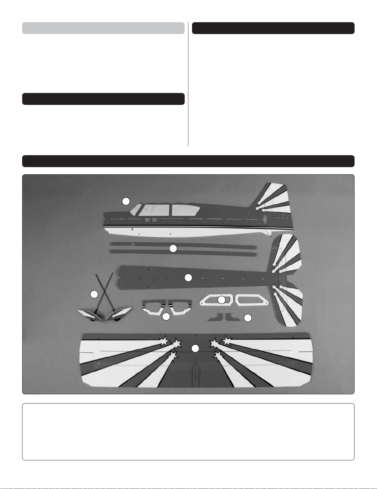
KIT CONTENTS
1
Carefully remove the major parts from the kit. Take an inventory
to make sure it is complete, and inspect the parts to make
sure they are of acceptable quality. If any parts are damaged
or missing or are not of acceptable quality, or if you need
assistance with assembly, contact Product Support. When
reporting defective or missing parts, use the part names
exactly as they are written in the Kit Contents list.
Great Planes Product Support
3002 N Apollo Drive, Suite 1
Champaign, IL 61822
Ph: (217) 398-8970, ext. 5
Fax: (217) 398-7721
E-mail: airsupport@greatplanes.com
4
Kit Contents
5
2
8
1. Vertical Fuselage
2. Horizontal Fuselage
3. Wing
4. Landing Gear
7
6
3
5. Diagonal Support
6. Upper Motor Doubler
7. Horizontal Fuselage Doubler
8. Vertical Fuselage Doubler
4
BUILD THE FUSELAGE
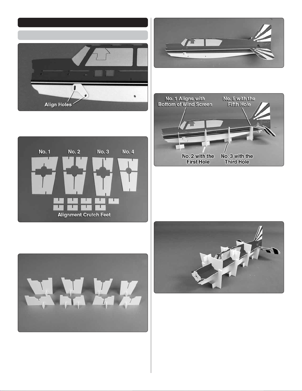
Assemble the Fuselage
1. Locate the two ABS landing gear supports. Glue
❏
a landing gear support to each side of the fuselage in the
location shown.
4. Insert the aft end of the horizontal fuselage into the
❏
front of the vertical fuselage. Key the horizontal and vertical
fuselages together.
2. Remove the nine fuselage alignment crutches from
❏
the surrounding foam. Note: Use a sharp hobby knife to cut
the crutch parts from the surrounding foam, trimming the tabs
fl ush with the edges of the crutches.
3. To prevent the parts from adhering to your building table,
❏
place a piece of waxed paper, or the clear plastic bag the
parts came in, on your table. Use foam safe CA to glue the
nine alignment crutch feet to the alignment crutches. Make
sure the crutches and feet are fl at against the building table
and that the crutches are perpendicular to the table.
5. On your building table, place the four bottom crutches
❏
with the feet on them underneath the fuselage in the locations
shown. Crutch #1 is positioned in line with the bottom of the
windscreen. Crutch #2 is positioned at the fi rst hole in the
side of the fuselage. Crutch #3 is positioned at the third hole
in the side of the fuselage. Crutch #4 is positioned at the fi fth
hole in the side of the fuselage, just under the leading edge
of the stabilizer.
6. Test fi t the #1, #2 and #3 top crutches over their
❏
corresponding bottom crutches. Install the ABS motor mount
onto the front of the fi rewall, but DO NOT glue it in place at
this time. Check that all the crutches are seated against the
fuselage and the horizontal and vertical fuselages are keyed
together. Then, glue the top and bottom of crutches #1, #2
and #3 together by applying small amount of foam-safe CA to
the tabs of the crutches. Be careful not to glue the crutc hes
to the fuselage.
7. Position the #4 top crutch over the corresponding #4
❏
bottom crutch.
5
8. Make sure the horizontal and vertical fuselages are keyed
❏
together and the crutches are fl at on your building table. Glue
the horizontal and vertical fuselages together by applying thin
foam-safe CA along the joint between the two. Be careful when
gluing around the crutches. DO NOT glue the crutches to the
fuselage. Allow the CA to cure for a few minutes before moving
the plane. The use of foam-safe accelerator will quicken the
curing of the CA, but use it sparingly. Excessive amounts of
accelerator can cause the CA to cure quickly, causing it to
get hot and melt the foam.
and #4 crutches are fl at on the building table. The #2 building
crutch should be fl at on the wing. Check that the horizontal
and vertical fuselages are keyed together. Use foam-safe CA
to glue the bottom of the horizontal and vertical fuselages
together and the wing and vertical fuselage together.
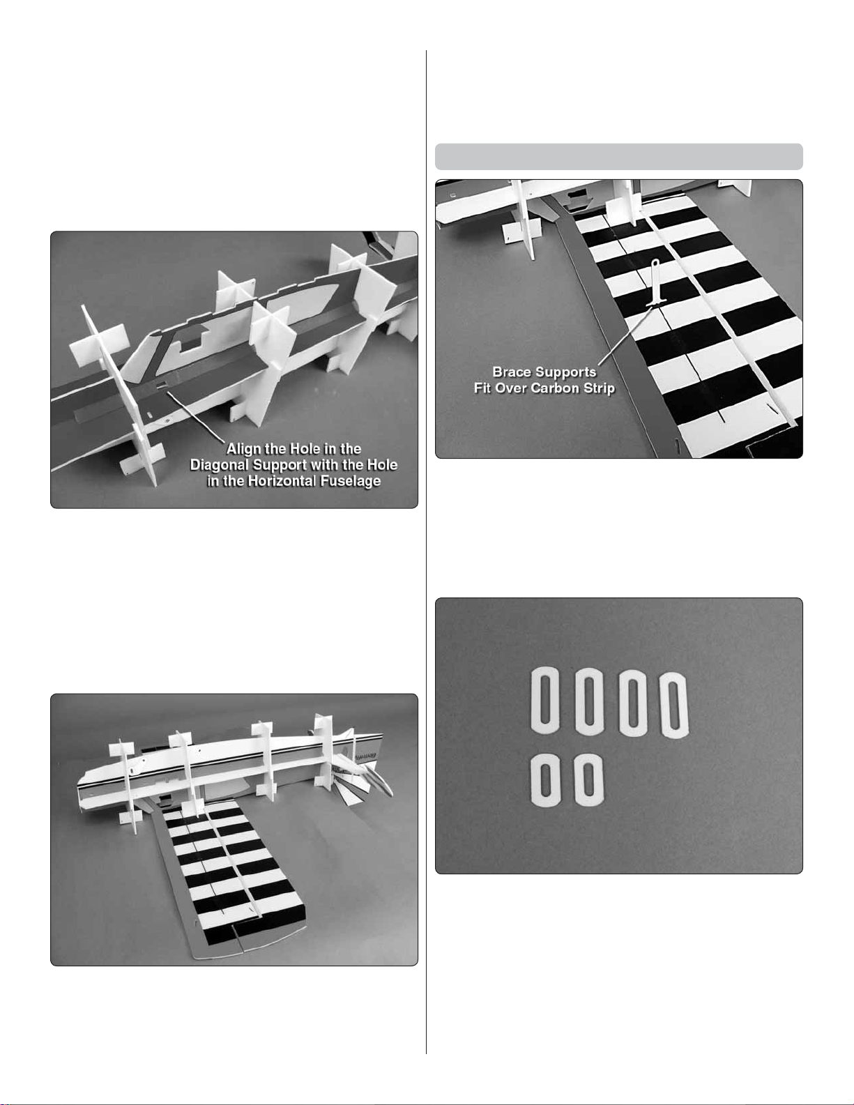
Install the Wing Supports
9. On the left side of the fuselage, from the aft end, slide the
❏
diagonal support with the hole in it, under the crutches. Align
the hole in the diagonal support with the hole in the horizontal
fuselage. Use foam-safe CA to glue the diagonal support at a
45 degree angle against the horizontal and vertical fuselages.
10. Insert and glue the second diagonal support on the
❏
right side of the fuselage. Make sure the aft end of the right
diagonal support is the same distance from the rudder hinge
line as the left diagonal support.
1. Locate the two ABS brace supports. There is a slot
❏
located in the center of each wing. Glue the ABS brace
supports into the slots, perpendicular to the underside of the
wing. It is possible that, during manufacturing, some glue
may have gotten into the slot. If this has happened, DO NO T
FORCE the supports into the slot. Use a sharp hobby knife
to remove any excess glue.
11. Place the wing upside down on the building table.
❏
Carefully turn the Citabria over and key the top of the fuselage
into the bottom of the wing. Note that the vertical fi n will need
to hang over the edge of the building table. Check that #1, #3
2. Locate the four long and two medium ABS brace
❏
doublers
Note: For steps 3 through 5, DO NOT glue the parts until
told to do so.
6
 Loading...