

Page 1
WARRANTY
Great Planes
®
Model Manufacturing Co. guarantees this kit to be free from defects in both material and workmanship at the date of
purchase.This warranty does not cover any component parts damaged by use or modification. In no case shall Great Planes’ liability
exceed the original cost of the purchased kit. Further, Great Planes reserves the right to change or modify this warranty without notice.
In that Great Planes has no control over the final assembly or material used for final assembly, no liability shall be assumed nor
accepted for any damage resulting from the use by the user of the final user-assemb led product.By the act of using the user-assembled
product, the user accepts all resulting liability.
If the buyer is not prepared to accept the liability associated with the use of this product, the buyer is advised to return this
kit immediately in new and unused condition to the place of purchase.
To make a warranty claim send the defective part or item to Hobby Services at the address below:
Hobby Services
3002 N. Apollo Dr., Suite 1
Champaign, IL 61822 USA
Include a letter stating your name, return shipping address, as much contact information as possible (daytime telephone number, fax
number, e-mail address), a detailed description of the problem and a photocopy of the purchase receipt. Upon receipt of the package
the problem will be evaluated as quickly as possible.
READ THROUGH THIS MANUAL BEFORE STARTING
CONSTRUCTION. IT CONTAINS IMPORTANT INSTRUCTIONS
AND WARNINGS CONCERNING THE ASSEMBLY AND
USE OF THIS MODEL.
GPMZ1122 for GPMA1122 V1.0Entire Contents © Copyright 2006
Champaign, Illinois
(217) 398-8970, Ext 5
INSTRUCTION MANUAL
Wingspan: 36 in [915mm]
Wing Area: 238 sq in [15.4dm2]
Weight: 7.5 – 8.5 oz [215 – 240g]
Wing Loading: 4.5 – 5.1 oz/sq ft [14 – 16g/dm2]
Length: 25 in [635mm]
Radio: 4-channel minimum, 3 micro servos, 7A brushed ESC
and micro receiver
Page 2
2
INTRODUCTION ...............................................................2
AMA...................................................................................2
SAFETY PRECAUTIONS..................................................2
LITHIUM BATTERY HANDLING & USAGE.....................3
DECISIONS YOU MUST MAKE........................................3
Radio Equipment & Electronics...................................3
Electronic Speed Control (ESC)..................................4
ADDITIONAL ITEMS REQUIRED.....................................4
Adhesives & Building Supplies....................................4
Optional Supplies & Tools ...........................................4
IMPORTANT BUILDING NOTES......................................4
ORDERING REPLACEMENT PARTS ..............................4
KIT INSPECTION..............................................................5
KIT CONTENTS ................................................................5
ASSEMBLE THE AIRPLANE............................................6
Install the Aileron Servo..............................................6
6 Install the Wing Panels................................................6
Assemble the Aileron Pushrods..................................7
Install the Horizontal Stabilizer........................................8
Install the Tail Servos & Linkages ...............................8
Install the Electronics & Propeller ...............................9
Combat Setup ...........................................................10
GET THE MODEL READY TO FLY .................................11
Check the Control Directions ....................................11
Set the Control Throws..............................................11
Balance the Model (C.G.)..........................................11
PREFLIGHT.....................................................................12
Identify Your Model ....................................................12
Charge the Batteries .................................................12
Range Check.............................................................12
AMA SAFETY CODE (excerpts)....................................12
CHECK LIST ...................................................................13
FLYING ............................................................................13
Launch.......................................................................13
Flight..........................................................................13
Landing......................................................................14
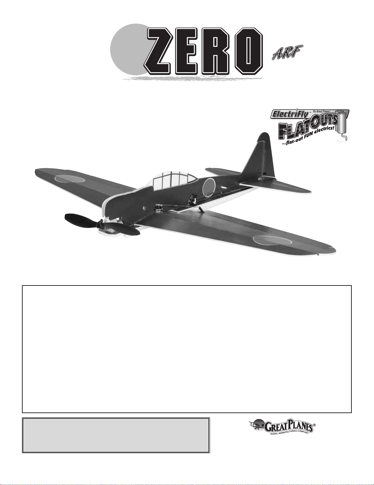
Thank you for y our purchase of the Great Planes ElectriFly
™
FlatOuts Zero ARF! Whether flying aerobatics by y ourself , or
challenging another flat fighter to combat using the tail
streamers, this model is sure to provide you many hours of
entertainment. These flat fighters can be assembled in as
little as an hour, and their f oam construction can be repaired
on site to get you back into combat as quickly as it takes to
top off the battery in your radio.The FlatOuts Zero ARF can
comfortably fly in a gymnasium at slow speeds, or fly with
authority outdoors on a day with light winds. And the best
feature, the economical price and quick build time of the
FlatOuts Zero ARF will allow you to fly combat aggressively
without the worry of damage to an expensive or time
consuming model.
For the latest technical updates or manual corrections to the
Great Planes FlatOuts Zero ARF visit the Great Planes web site
at www.greatplanes.com.Open the “Airplanes” link, and then
select the FlatOuts Zero ARF. If there is new technical
information or changes to this model, a “tech notice” box will
appear in the upper left corner of the page.
We urge you to join the AMA (Academy of Model
Aeronautics) and a local R/C club.The AMA is the governing
body of model aviation and membership is required to fly at
AMA clubs.Though joining the AMA provides many benefits,
one of the primary reasons to join is liability protection.
Coverage is not limited to flying at contests or on the club
field. It even applies to flying at public demonstrations and
air shows. Failure to comply with the Safety Code (excerpts
printed in the back of the manual) may endanger insurance
coverage.Additionally, training programs and instructors are
available at AMA club sites to help you get started the right
way. There are over 2,500 AMA chartered clubs across the
country. Contact the AMA at the address or toll-free phone
number below.
IMPORTANT!!! T w o of the most important things you can do
to preserve the radio controlled aircraft hobby are to avoid
flying near full-scale aircraft and avoid flying near or over
groups of people.
1.Your FlatOuts Zero ARF should not be considered a toy, but
rather a sophisticated, working model that functions very
much like a full-size airplane. Because of its performance
capabilities, the FlatOuts Zero ARF, if not assembled and
operated correctly, could possibly cause injur y to yourself or
spectators and damage to property.
2. You must assemble the model according to the
instructions. Do not alter or modify the model, as doing so
may result in an unsafe or unflyable model. In a few cases
the instructions may differ slightly from the photos.In those
instances the written instructions should be considered
as correct.
PRO TECT YOUR MODEL,Y OURSELF
& OTHERS...FOLLOW THESE
IMPORTANT SAFETY PRECAUTIONS
Academy of Model Aeronautics
5151 East Memorial Drive
Muncie, IN 47302
Tele: (800) 435-9262
Fax (765) 741-0057
Or via the Internet at:
http://www.modelaircraft.org
AMA
INTRODUCTION
TABLE OF CONTENTS
Page 3
3.You must take time to build straight, true and strong.
4.You must correctly install all R/C and other components so
that the model operates correctly on the ground and in the air .
5.You must check the operation of the model before every
flight to insure that all equipment is operating and that the
model has remained structurally sound. Be sure to check
clevises or other connectors often and replace them if they
show any signs of wear or fatigue.
6. If you are not an experienced pilot or have not flown this
type of model before, we recommend that you get the
assistance of an experienced pilot in your R/C club for your
first flights.If you’re not a member of a club, your local hobb y
shop has information about clubs in your area whose
membership includes experienced pilots.
Remember:Take your time and follow the instructions to
end up with a well-built model that is straight and true.
WARNING!! Read the entire instruction sheet included with
this battery. Failure to follow all instructions could cause
permanent damage to the battery and its surroundings, and
cause bodily harm!
• ONLY use a LiPo approved charger. NEVER use a
NiCd/NiMH peak charger!
• NEVER charge in excess of 4.20V per cell.
• ONLY charge through the “charge” lead. NEVER charge
through the “discharge” lead.
• NEVER charge at currents greater than 1C.
• ALWAYS set charger’s output volts to match battery volts.
• ALWAYS charge in a fireproof location.
• NEVER trickle charge.
• NEVER allow the battery temperature to exceed 150° F
[65° C].
• NEVER disassemble or modify pack wiring in any wa y or
puncture cells.
• NEVER discharge below 2.5V per cell.
• NEVER place on combustible materials or leave
unattended during charge or discharge.
• ALWAYS KEEP OUT OF REACH OF CHILDREN.
This is a partial list of items required to finish the FlatOuts Zero
ARF that may require planning or decision making before
starting to build. Order numbers are provided in parentheses.
The FlatOuts Zero ARF requires a 4-channel or greater
transmitter, a micro receiver, and three micro servos (9g or
less). If you already have a transmitter you are going to use
to fly the FlatOuts Zero ARF, you can get the receiver and
servos separately:
• Futaba®R114F 4-channel FM micro receiver w/o crystal
(low band – FUTL0442, high band – FUTL0443)
• Futaba FM single conversion receiver crystal for R114F
(low band – FUTL62**, high band – FUTL63**)
• Futaba S3110 micro servo 7.7g (FUTM0046)
Or, you can purchase a complete system (including
transmitter) specially packaged for park flyers. If purchasing
a complete system, the Futaba 4YF Skysport FM radio is
suitable. It comes with a micro receiver and two Futaba
S3108 micro servos. One additional servo will need to be
purchased. The transmitter is also equipped with a
rechargeable NiCd battery pack:
• Futaba 4YF Skysport FM radio system including
transmitter, receiver, and servos (FUTJ36**)
• Futaba S3114 micro servo 7.7g (FUTM0414)
An 11.1V 350mAh or 11.1V 640mAh LiPo battery pack and
suitable charger are also required. Although there are
different battery packs and chargers available that will work
with the FlatOuts Zero ARF, the economical choices
recommended by Great Planes are:
• Great Planes 11.1V 350mAh 3S 20C discharge 2-pin
LiPo (GPMP0801) (Note:When using with the C-7 Nano
ESC, adapter required – GPMM3135)
• Great Planes 11.1V 640mAh 3S 15C discharge micro
LiPo (GPMP0805)
• Great Planes 11.1V 640mAh 20C discharge with
balance LiPo (GPMP0601) (Note: This requires the
Equinox™Cell Balancer – GPMM3160)
A suitable LiPo charger is required:
• Great Planes PolyCharge4™DC only 4 output LiPo
charger (GPMM3015)
or
• Great Planes ElectriFly™Triton™2 DC Peak
Charger (GPMM3153)
Radio Equipment & Electronics
DECISIONS YOU MUST MAKE
LITHIUM BATTER Y HANDLING & USAGE
We, as the kit manuf acturer, provide you with a top quality ,
thoroughly tested kit and instructions, but ultimately the
quality and flyability of your finished model depends on
how you build it; therefore, we cannot in any way
guarantee the performance of your completed model, and
no representations are expressed or implied as to the
performance or safety of your completed model.
3
Page 4
An electronic speed control (ESC) with BEC (Battery
Eliminator Circuitry) is required. The BEC allows both the
motor and the radio system to be powered by the same
battery (thus eliminating the on-board receiver battery). The
Great Planes ElectriFly C-7 Nano Brushed ESC
(GPMM2005) is recommended.
❏ Great Planes Pro
™
Foam Safe CA- Thick Glue
1 oz. (GPMR6072)
❏ Dr ill bits: 3/64" [1.2mm] or #60
❏ #1 Hobby knife (HCAR0105)
❏ Hobbico
®
soldering iron 60 Watt (HCAR0776)
❏ Denatured Alcohol
❏ Fine gr it sandpaper (320-grit)
Here is a list of optional tools that will help you build the
FlatOuts Zero ARF.
❏ 2 oz. [57g] spray foam safe CA activator (GPMR6035)
❏ 4 oz. [113g] aerosol foam safe CA activator (GPMR6034)
❏ CA applicator tips (HCAR3780)
❏ CA debonder (GPMR6039)
❏ Hobbico Pin Vise 1/16" collet w/6 bits (HCAR0696)
❏ Hobbico High Precision diagonal cutter 5" (HCAR0630)
❏ Pliers with wire cutter (HCAR0625)
❏ AccuThrow
™
deflection gauge (GPMR2405)
❏ CG Machine
™
(GPMR2400)
❏ Hobbico flexible 18" ruler stainless steel (HCAR0460)
• When you see the term
test fit
in the instructions, it
means that you should first position the part on the
assembly without using any glue, then slightly modify or
custom fit
the part as necessar y for the best fit.
• Whenever the term
glue
is written you should rely upon
your experience to decide what type of glue to use.When a
specific type of adhesive works best for that step, the
instructions will make a recommendation.
•
Photos
and
sketches
are placed before the step they
refer to. Frequently you can study photos in following steps
to get another view of the same parts.
Replacement parts for the Great Planes FlatOuts Zero ARF
are available using the order numbers in the Replacement
Parts List that follows. The fastest, most economical service
can be provided by your hobby dealer or mail-order company.
To locate a hobby dealer, visit the Hobbico web site at
www.hobbico.com. Choose “Where to Buy” at the bottom
of the menu on the left side of the page. Follow the
instructions provided on the page to locate a U.S., Canadian
or International dealer.
Parts may also be ordered directly from Hobby Services by
calling (217) 398-0007, or via facsimile at (217) 398-7721,
but full retail prices and shipping and handling charges will
apply. Illinois and Nevada residents will also be charged
sales tax. If order ing via fax, include a Visa®or MasterCard
®
number and expiration date for payment.
Mail parts orders and payments by personal check to:
Hobby Services
3002 N. Apollo Drive, Suite 1
Champaign, IL 61822
Be certain to specify the order number exactly as listed in
the Replacement Parts List. Payment by credit card or
personal check only; no C.O.D.
If additional assistance is required for any reason contact Product
Support by e-mail at [email protected], or by
telephone at (217) 398-8970.
Description How to Purchase
Missing pieces Contact Product Support
Instruction manual Contact Product Support
Full-size plans Not available
Kit parts listed below Hobby Supplier
Replacement Parts List
GPMG0420 ............180 Motor & 5:1 Ratio Gearbox
GPMG0292 ............180 Motor with Leads & Connectors
GPMG0182 ............Gearbox with Spur Gear/Shaft 5:1 Ratio
GPMG0863 ............Spur Gear/Shaft
GPMQ4619 ............Prop Saver O-ring
GPMQ4620 ............Prop Saver
ORDERING REPLACEMENT PARTS
IMPORTANT BUILDING NOTES
Optional Supplies & Tools
Adhesives & Building Supplies
ADDITIONAL ITEMS REQUIRED
Electronic Speed Control (ESC)
4
Page 5
5
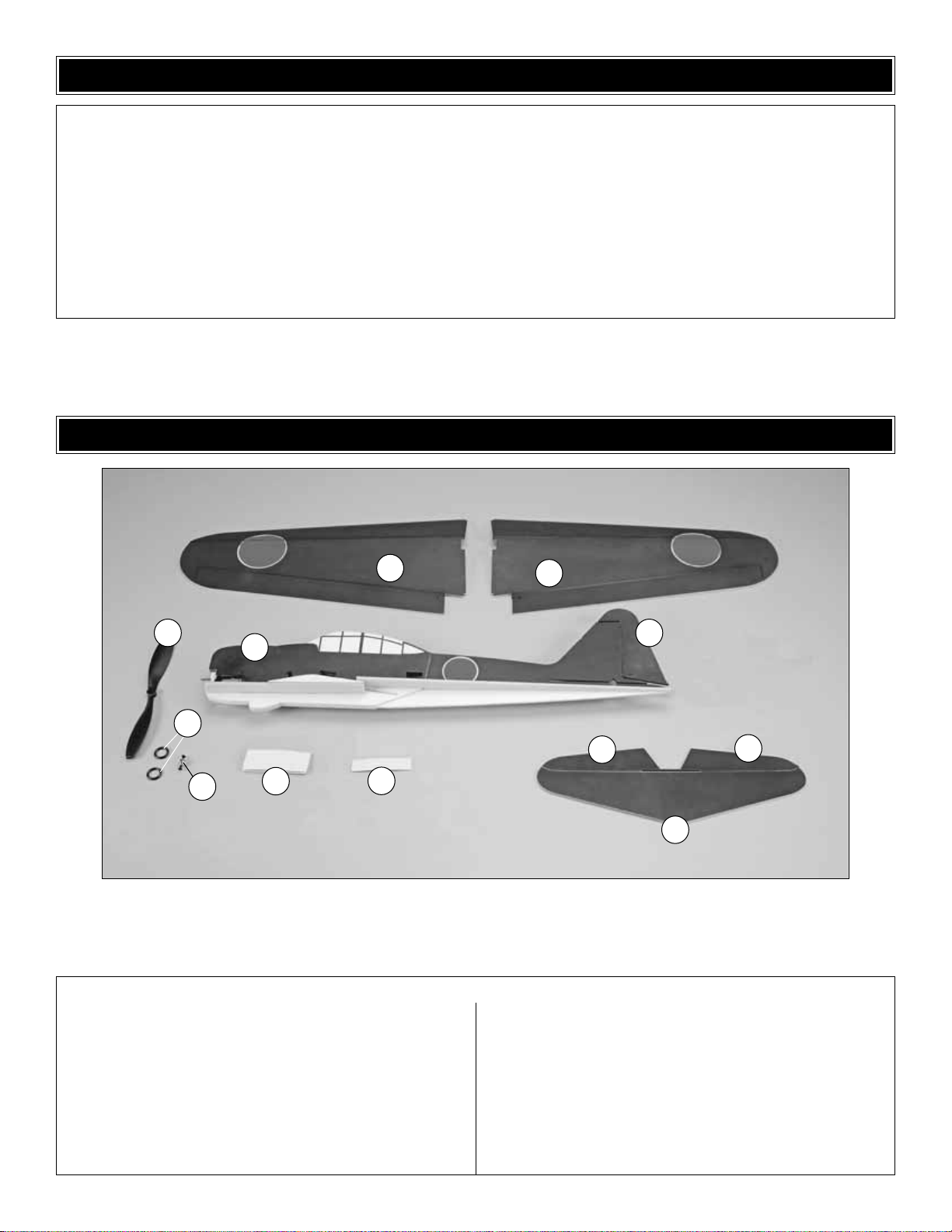
Before starting to build, take an inventory of this kit to make sure it is complete, and inspect the parts to make sure they
are of acceptable quality. If any parts are missing or are not of acceptable quality, or if you need assistance with assembly,
contact Product Support. When repor ting defective or missing parts, use the part names exactly as they are written in
the Kit Contents list on this page.
Great Planes Product Support
3002 N. Apollo Drive, Suite 1
Champaign, IL 61822
Telephone: (217) 398-8970, ext. 5
Fax: (217) 398-7721
E-mail: [email protected]
KIT INSPECTION
1. Left Wing Panel
2. Right Wing Panel
3. Propeller
4. Prop Saver O-rings (2)
5. Prop Saver
6. Fuselage
7. Hook & Loop Material
8. Double-sided Tape
9. Rudder
10. Elevator Halves (L&R)
11. Horizontal Stabilizer
Kit Contents
KIT CONTENTS
1
8
10
10
6
3
7
11
9
2
4
5
Page 6
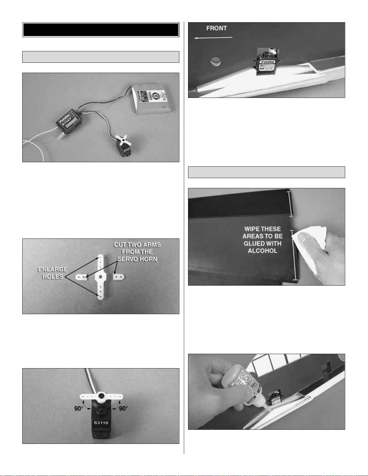
❏ 1. Connect the aileron servo to the receiver. Use your
ESC or a receiver pack to power the receiver. Turn on your
transmitter and center the aileron servo. Do not skip this
step, as the aileron servo must be installed into the fuselage
with the servo horn attached to it.
❏ 2. Cut two ar ms from a four-arm servo horn as shown.
Enlarge the outer holes in the remaining servo arms with a
3/64" [1.2mm] drill bit.
❏ 3. Install the ser vo horn perpendicular to the servo case.
❏ 4. Feed the aileron servo wire out of the right side of the
aileron servo bay. Fit the aileron ser vo into the aileron servo
bay with the servo spline towards the rear of the plane .Apply a
couple of drops of thick foam safe CA glue to each servo case
tab, securing the servo to the fuse.Add a couple of drops of CA
glue near the base of the servo case as well.It does not require
much CA glue to secure the servo to the fuse.Excess glue will
simply make it difficult to remove the servo in the future.
❏❏1. For the best adhesion on the painted surfaces,we
recommend roughing up the painted surfaces to be glued
with fine grit sandpaper such as 320-grit. Wiping the areas
to be glued with a paper towel dampened with denatured
alcohol will reduce the gloss of the paint and also improve
adhesion. If using alcohol, we recommend only making one
pass with the towel. Excessive wiping will completely
remove the paint from the foam.
❏❏2.Apply a bead of thick CA glue to the tops of the wing
supports on the left side of the fuse. We recommend using
CA accelerator to speed assembly time.
Install the Wing Panels
Install the Aileron Servo
ASSEMBLE THE AIRPLANE
6
Page 7
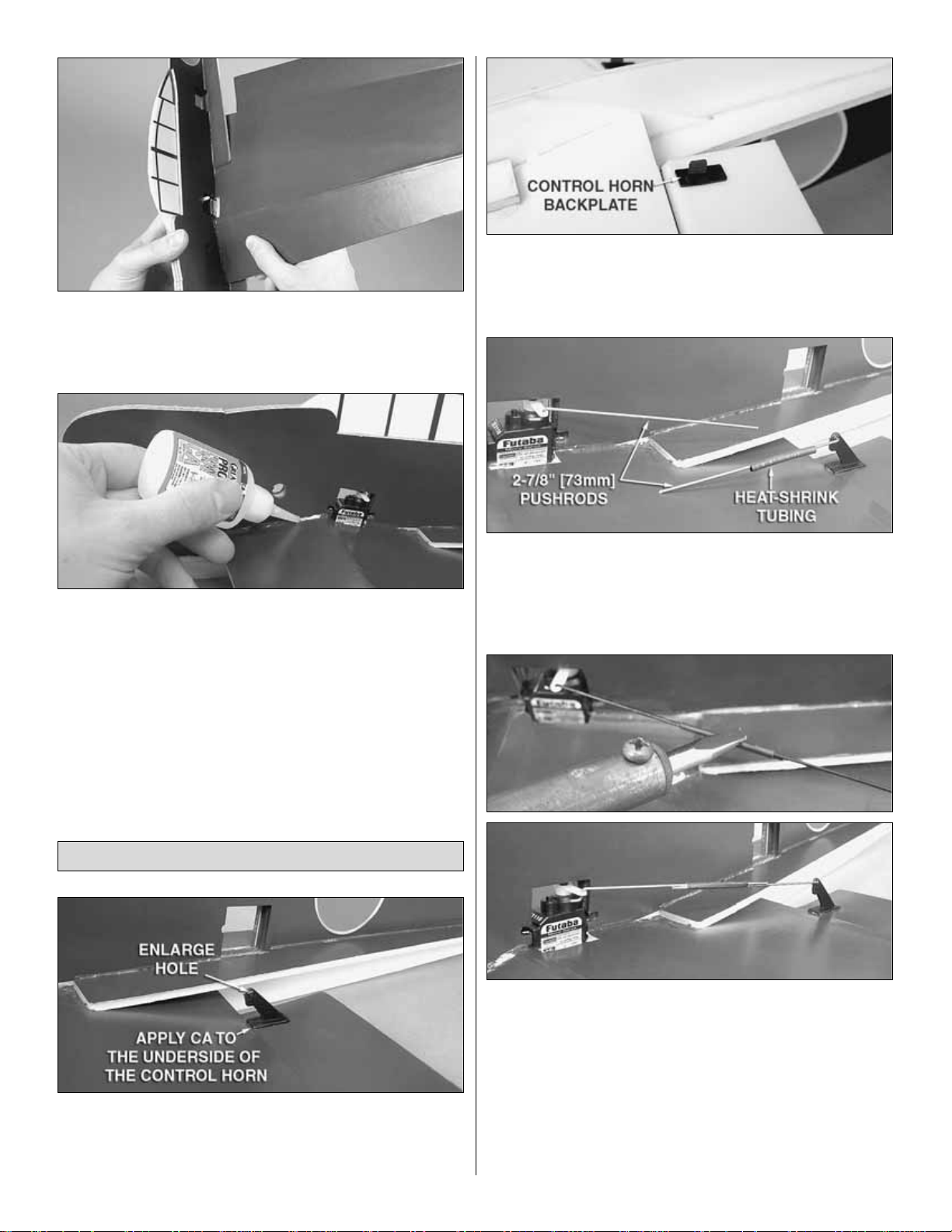
❏❏3. Insert the left wing panel into the slot.The notch at
the inside LE of the wing panel will contact the fuse when
fully seated.The TE of the wing panel must be aligned with
the center of the fuse.
❏❏4. Apply a bead of CA around the joint between the
wing and the fuse on the top and bottom.
❏ 5. Repeat this procedure for the right wing panel.Be
sure the aileron servo lead exits the right side of the servo
bay above the wing panel.
❏ 1 . Enlarge the outer holes of the two control horns with a
3/64" [1.2mm] drill bit.Apply a couple drops of CA glue to the
underside of the control horn backplates. Push the control
horn tabs through the slots in the ailerons as shown.
❏ 2. Press the control horn backplates onto the tabs to secure
the control horns to the ailerons. Glue the backplates to the
control horn tabs with a drop of CA.
❏ 3. Locate the four 2-7/8" [73mm] pushrods and hook the
Z-bends into the outer holes of the servo horn and the outer
holes of the control horns. Slide a piece of 1" [25mm] heatshrink tubing onto one of the pushrods for each wing panel.
❏ 4. Overlap the pushrod ends and join them with the heat-
shrink tubing.Position the ailerons in the neutral position and
tape or hold them in place. Carefully use a solder ing iron to
shrink the tubing around the pushrods. Keep the iron away
from the foam and move it quickly back and forth across the
heat-shrink tubing until the pushrods are joined together tightly .
We do not suggest using a heat gun or micro torch to
shrink the tubing as this will melt the foam that is close to
the pushrods. When satisfied, apply a couple drops of CA
glue to each end of the heat-shrink tubing.
Assemble the Aileron Pushrods
7
Page 8
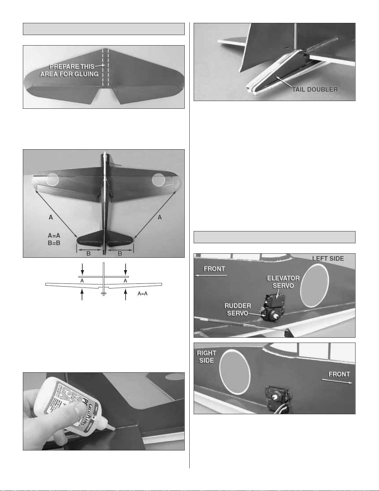
❏ 1. Roughen a 1/8" [3mm] strip down the center of the top
and bottom of the horizontal stabilizer. Use alcohol to dull
the paint at the area to be glued. Do the same to the area
around the horizontal stab slot in the fuse.
❏ 2. Center the stab left and right in the fuse. Make sure the
stab is square to the fuse by measuring the distance
between the wing tips and stab tips and setting them equal
to each other as shown in the photo. Before gluing, stand
back several feet and view the model from behind.The stab
should be parallel to the wing.If not, you will need to hold the
stab in the correct position as you glue it to the fuse.
❏ 3.When satisfied, run a bead of thick CA glue along the top
and bottom of the stab where it meets the fuse on both sides.
❏ 4. Glue the two tail doublers to the aft end of the fuse
as shown.
❏ 1. Glue the rudder and elevator servos into the cutout in
the fuse with the output splines both facing the front of the
plane.The servo in the bottom of the slot is the rudder servo
and should be installed with the splines on the left side of
the fuse.The servo in the top of the slot is the elev ator servo
and should be installed with the splines on the right side of
the fuse. Both ser vo leads should exit out of the right side.
Install the Tail Servos & Linkages
Install the Horizontal Stabilizer
8
Page 9
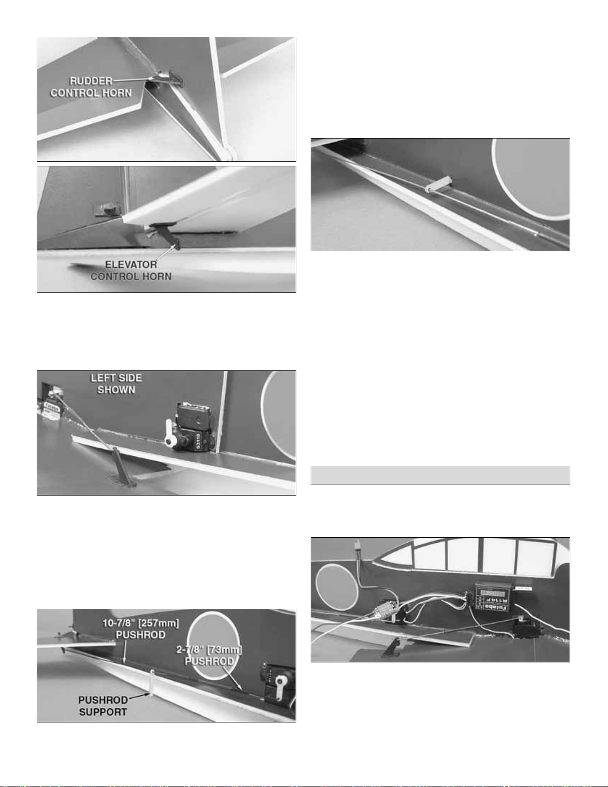
❏ 2 . Enlarge the outer hole of a control hor n using a 3/64"
[1.2mm] drill bit. Install the control hor n onto the left side of
the rudder. Enlarge the inner hole (closest to the control
horn base) of another control horn using the same drill bit
and install it on the bottom of the right elevator half.
❏ 3. Use your radio system to center the elevator and rudder
servos. Cut three arms from two four-arm servo horns and
install them onto the elevator and rudder servos, with the right
one pointing down and the left one pointing up. Enlarge the
outer holes of the servo horns and the rudder control horn
with a 3/64" [1.2mm] drill bit. Enlarge the inner hole of the
elevator control horn (closest to the elevator) with the same
size bit.
❏ 4.Hook the remaining two 2-7/8" [73mm] pushrods onto the
elevator and rudder servo horns.Connect the 10-1/8" [257mm]
pushrods onto the inner hole of the elevator control horn and
outer hole of the rudder control horn. Slide a pushrod suppor t
onto each 10-1/8" [257mm] pushrod. If necessary, enlarge the
holes in the pushrod supports to prevent binding. As you did
with the aileron pushrods, join the elevator and rudder
pushrods together with a 1" [25mm] piece of heat-shrink tubing
while centering the control surfaces.Apply a drop of CA to the
ends of the heat-shrink tubing.
❏ 5. Position the pushrod supports in the middle of the
pushrods and lightly press them into the fuse, creating
indentations in the foam. Be sure that the pushrod support
location will not create any binding in the pushrod. Use a
sharp hobby knife to cut a hole in the foam at the
indentations you made.Insert the pushrod supports into the
holes and glue them in place.
Note: Consult the directions that came with the ElectriFly ESC
for proper operation.
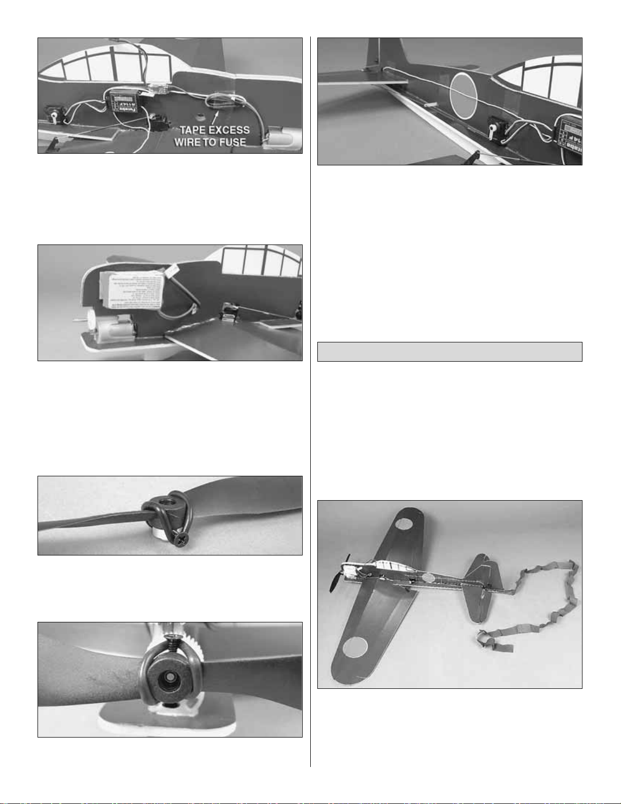
❏ 1.Cut a piece of the included double-sided tape to fit your
receiver and stick it to the underside of the receiver case.
Connect the ESC, aileron, rudder, and ele v ator servos to the
receiver. Peel the backing from the double-sided tape and
secure the receiver to the fuse in the location shown in the
photo. Be sure that you have the servo wires positioned so
that they do not interfere with the pushrods.
Install the Electronics & Propeller
9
Page 10
❏ 2. Connect the ESC motor leads to the banana plugs on
the motor. Secure the ESC to the fuse with double-sided
tape as far forward as the wires will allow. Use a piece of
clear tape (not included) to hold the excess motor lead wires
against the fuse. Use alcohol to dull the painted surfaces
where the tape will be applied.
❏ 3. In order to balance the FlatOuts Zero ARF without the
addition of weight, the battery pack must be secured above the
motor.Use the included hook and loop material to do so with
the “loop” side on the batter y. Applying the “loop” side of the
hook and loop material to the front side of the battery will allow
the battery discharge leads to reach the ESC battery
connectors.The discharge leads will pass through the hole in
the fuse to connect to the ESC.
❏ 4. Loop the prop saver O-ring around one of the screws
and over the prop hub.Hook the O-ring onto the other screw
to secure the propeller to the prop saver .Long nose pliers may
make it easier to stretch the O-ring onto the screws.
❏ 5. Attach the prop saver by tightening the two screws
against the flat spots on the prop shaft.
❏ 6.The receiver antenna can be taped to the side of the fuse.
However, be sure not to let excess wire hang free of this
airplane if you plan to fly combat. Use alcohol to dull the
painted surfaces where the tape will be applied. Wrap the
excess wire through the elevator joiner tube cutout and tape it
to the other side of the fuse. For a cleaner look, you can also
cut a slit in the fuse and embed the antenna out of sight.
The Great Planes FlatOuts Zero ARF was designed with the
intention that two or more of these models can be flown
together in classic dogfight style. Paper streamers are
included with the model to be taped to the rear of the fuse.
Rubber bands are also included to attach the streamer.To
use the rubber band, drill a small hole in the tail of the plane
and loop a rubber band through the hole and around the
streamer.During combat, use the propeller on your fighter to
cut the streamer on the enemy.
❏ 1. Damage to your plane is inevitable during this kind of
combat. However, the simplicity of this model allows it to be
repaired quickly at the flying site. Be sure to put some thick
foam-safe CA glue and CA activator in your field box, and
you will be able to be back in flight in a matter of minutes
should repair be necessary.
Combat Setup
10
Page 11
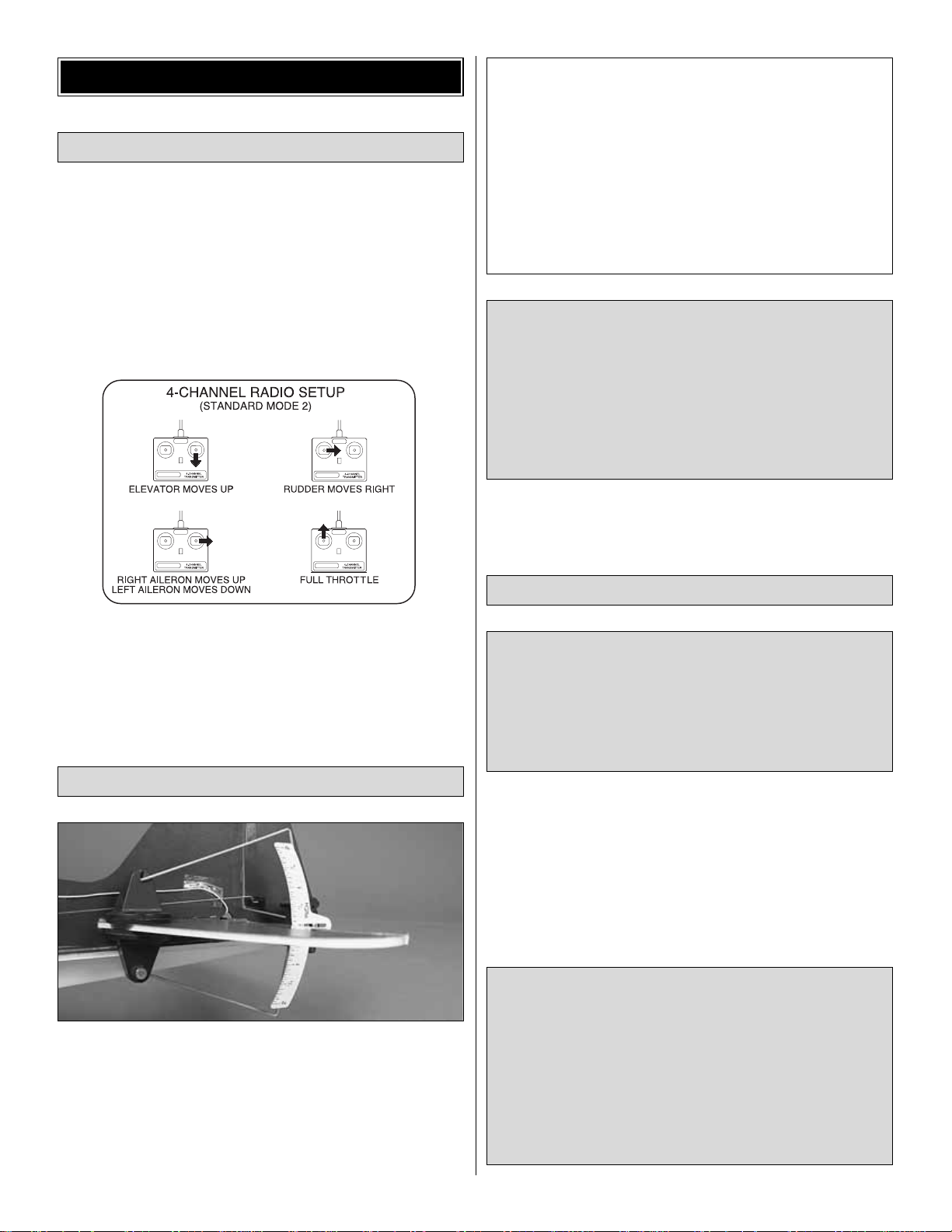
❏ 1. T urn on the transmitter and receiv er and center the trims.
❏ 2. With the transmitter and receiver still on, check all the
control surfaces to see if they are centered.If the lengths of
the pushrods need to be adjusted to center the control
surfaces, break the glue bond at the ends of the heat-shrink
tubing and make your adjustments. Be sure to re-glue the
ends of the heat-shrink tubing to the pushrod wires when
you are satisfied.
❏ 3. Make certain that the control surfaces and the throttle
respond in the correct direction as shown in the diagram. If
any of the controls respond in the wrong direction, use the
servo reversing in the transmitter to reverse the servos
connected to those controls. Be certain the control surfaces
have remained centered.
Use a Great Planes AccuThrow (or a ruler) to accurately
measure and set the control throw of each control surface as
indicated in the chart that follows.If your radio does not hav e
dual rates, we recommend setting the throws at the low
rate setting.
Note: The throws are measured at the widest part of the
elevator, r udder and ailerons.
At this stage the model should be in ready-to-fly condition
with all of the systems in place including the receiver , battery
and ESC.
❏ 1. Use a felt-tip pen or 1/8" [3mm]-wide tape to accurately
mark the C.G. on the top of the wing on both sides of the
fuse.The C.G.is located 2-5/8" [67mm] back from the LE of
the wing at the fuse.
This is where your model should balance for the first flights.
Later, you may wish to experiment by shifting the C.G. up to
1/8" [3mm] forward or 3/8" [9.5mm] back to change the flying
characteristics. Moving the C.G. forward may improve the
smoothness and stability , but the model ma y then require more
speed for takeoff and mak e it more difficult to slo w for landing.
Moving the C.G.aft makes the model more maneuverable, but
could also cause it to become too difficult to control. In any
case, star t at the recommended balance point and do not
at any time balance the model outside the specified range.
More than any other factor, the C.G. (balance point) can
have the greatest effect on how a model flies, and may
determine whether or not your first flight will be
successful. If you value this model and wish to enjoy it for
many flights, DO NOT OVERLOOK THIS IMPORTANT
PROCEDURE. A model that is not proper ly balanced will
be unstable and possibly unflyable.
Balance the Model (C.G.)
IMPORTANT: The FlatOuts Zero ARF has been
extensively flown and tested to arrive at the throws at
which it flies best. Flying your model at these throws will
provide you with the greatest chance for successful first
flights. If, after you have become accustomed to the way
the FlatOuts Zero ARF flies, you would like to change the
throws to suit your taste, that is fine. However, too much
control throw could make the model difficult to control, so
remember, “more is not always better.”
These are the recommended control surface throws:
High Rate Low Rate
ELEVATOR: 3/4" [19mm] up 1/2" [13mm] up
3/4" [19mm] down 1/2" [13mm] down
RUDDER: 1" [25mm] right 1/2" [13mm] right
1" [25mm] left 1/2" [13mm] left
AILERONS: 1" [25mm] up 5/8" [16mm] up
1" [25mm] down 5/8" [16mm] down
Set the Control Throws
Check the Control Directions
GET THE MODEL READY TO FLY
11
Page 12
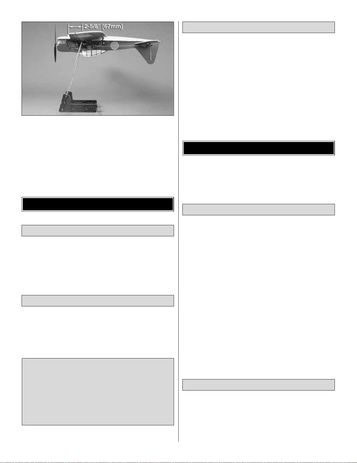
❏ 2.With all parts of the model installed (ready to fly), place
the model upside-down on a Great Planes CG Machine, or
lift it upside-down at the balance point you marked .
❏ 3. If the tail drops, the model is “tail heavy” and the battery
pack must be shifted forw ard to balance .If the nose drops, the
model is “nose heavy” and the batter y pack must be shifted
back to balance. This model is ver y weight sensitive. Do not
add any weight to achieve the suggested balance point.
Instead, shift the battery pack forward or aft to alter the C.G.
No matter if you fly at an AMA sanctioned R/C club site or if you
fly somewhere on your own, y ou should always ha ve your name,
address, telephone number and AMA number on or inside your
model. It is required at all AMA R/C club flying sites and AMA
sanctioned flying events .Fill out the identification tag on page 14
and place it on or inside your model.
Follow the battery charging instructions that came with your
radio control system to charge the batteries. You should
always charge your tr ansmitter and motor batteries the night
before you go flying, and at other times as recommended b y
the manufacturer.
Ground check the operational range of your r adio before the first
flight of the day. With the transmitter antenna collapsed and the
receiver and transmitter on, you should be able to walk at least
100 feet away from the model and still have control. Have an
assistant stand by your model and, while you w ork the controls,
tell you what the control surfaces are doing.Repeat this test with
the motor running at various speeds with an assistant holding
the model, using hand signals to show you what is happening.If
the control surfaces do not respond correctly, do not fly! Find
and correct the problem first. Look for loose servo connections
or broken wires, corroded wires on old servo connectors, poor
solder joints in your battery pack or a defective cell, or a
damaged receiver crystal from a previous crash.
Read and abide by the following excerpts from the Academy
of Model Aeronautics Safety Code.For the complete Safety
Code refer to
Model Aviation
magazine, the AMA web site or
the Code that came with your AMA license.
1) I will not fly my model aircraft in sanctioned events, air
shows, or model flying demonstrations until it has been
proven to be airworthy by having been previously,
successfully flight tested.
2) I will not fly my model aircraft higher than approximately
400 feet within 3 miles of an airport without notifying the
airport operator .I will give right-of-wa y and av oid flying in the
proximity of full-scale aircraft.Where necessary, an observer
shall be utilized to supervise flying to avoid having models
fly in the proximity of full-scale aircraft.
3) Where established, I will abide by the safety rules for the
flying site I use, and I will not willfully and deliberately fly my
models in a careless, reckless and/or dangerous manner.
5) I will not fly my model unless it is identified with my name
and address or AMA number, on or in the model.Note: This
does not apply to models while being flown indoors.
7) I will not operate models with pyrotechnics (any device
that explodes, burns, or propels a projectile of any kind).
1) I will have completed a successful radio equipment ground
check before the first flight of a new or repaired model.
2) I will not fly my model aircraft in the presence of
spectators until I become a qualified flier, unless assisted b y
an experienced helper.
Radio Control
General
AMA SAFETY CODE (excerpts)
Range Check
CAUTION: Unless the instructions that came with your
radio system state differently, the initial charge on new
transmitter batteries should be done for 15 hours using
the slow-charger that came with the radio system.This
will “condition” the batter ies so that the next charge may
be done using the fast-charger of your choice.If the initial
charge is done with a fast-charger, the batteries may not
reach their full capacity and you may be flying with
batteries that are only partially charged.
Charge the Batteries
Identify Y our Model
PREFLIGHT
12
Page 13
3) At all flying sites a straight or curved line(s) must be
established in front of which all flying takes place with the
other side for spectators.Only personnel involv ed with flying
the aircraft are allowed at or in the front of the flight line.
Intentional flying behind the flight line is prohibited.
4) I will operate my model using only radio control frequencies
currently allowed by the Federal Communications Commission.
5) I will not knowingly operate my model within three miles
of any pre-existing flying site except in accor dance with the
frequency sharing agreement listed [in the complete AMA
Safety Code].
9) Under no circumstances may a pilot or other person touch
a powered model in flight; nor should any part of the
model other than the landing gear, intentionally touch
the ground, except while landing.
❏ 1. Check the C.G. according to the measurements
provided in the manual.
❏ 2. Be certain the battery and receiver are securely
mounted to the fuse.
❏ 3. Confir m that all controls operate in the correct direction
and the throws are set up according to the manual.
❏ 4. Check the operation of the motor and gearbox prior to
each flight.
❏ 5. Make sure that all servo arms are secured to the
servos with the screws included with your radio.
❏ 6. Place your name, address, AMA number and
telephone number on or inside your model.
❏ 7. If you wish to photograph your model, do so before
your first flight.
❏ 8. Range check your radio when you get to the flying field.
❏ 9. Confirm that the hinge tape is properly secured.
The FlatOuts Zero ARF is a great-flying model that flies
smoothly and predictably. The FlatOuts Zero ARF does not,
however, possess the self-recovery characteristics of a
primary R/C trainer and should be flown only by experienced
R/C pilots.
For the first flight, it is a good idea to have a friend launch
the airplane for you.This allows you to keep your hands on
the radio sticks and correct any trim problems that are
present.Have your friend hold the FlatOuts Zero ARF by the
canopy. Throttle up to full power, and have your friend give
the plane a gentle underhanded toss at about a 30° angle
upward.Since the FlatOuts Zero ARF has a very high thrust
to weight ratio, the plane will accelerate to flying speed
almost instantly. Climb to a comfor table altitude and throttle
back to a lower pow er setting.This plane flies great at about
half-throttle when in standard forward flight.
For reassurance and to keep an eye on other traffic, it is a
good idea to have an assistant on the flight line with you.Tell
him to remind you to throttle back once the plane gets to a
comfortable altitude.While full throttle is usually desirable for
takeoff, most models fly more smoothly at reduced speeds.
Take it easy with the FlatOuts Zero ARF for the first few
Flight
Launch
CAUTION (THIS APPLIES TO ALL
R/C AIRPLANES): If,
while flying, you notice an alarming or unusual sound
such as a low-pitched “buzz,” this may indicate control
surface
flutter
.Flutter occurs when a control surface (such
as an aileron or elevator) or a flying surface (such as a
wing or stab) rapidly vibrates up and down (thus causing
the noise). In extreme cases, if not detected immediately,
flutter can actually cause the control surface to detach or
the flying surface to fail, thus causing loss of control
followed by an impending crash. The best thing to do
when flutter is detected is to slow the model immediately
by reducing power, then land as soon as safely possible.
Identify which surface fluttered (so the problem may be
resolved) by checking all the servo grommets for
deterioration or signs of vibration. Make certain all
pushrod linkages are secure and free of play. If it fluttered
once, under similar circumstances it will probably flutter
again unless the problem is fixed.Some things which can
cause flutter are; Excessive hinge gap; Not mounting
control horns solidly; Poor fit of clevis pin in horn; Sideplay of wire pushrods caused by large bends; Excessive
free play in servo gears; Insecure servo mounting; and
one of the most prevalent causes of flutter;Flying an overpowered model at excessive speeds.
FLYING
During the last few moments of preparation your mind may
be elsewhere anticipating the excitement of the first flight.
Because of this, you may be more likely to overlook certain
checks and procedures that should be performed before the
model is flown.To help avoid this, a check list is provided to
make sure these important areas are not overlooked. Many
are covered in the instruction manual, so where appropriate,
refer to the manual for complete instructions. Be sure to
check the items off as they are completed.
CHECK LIST
13
Page 14
flights, gradually getting acquainted with it as you gain
confidence. Adjust the trims to maintain straight and level
flight. After flying around for a while, and while still at a safe
altitude with plenty of battery power, practice slow flight and
execute pr actice landing approaches by reducing the throttle
to see how the model handles at slower speeds.Add power
to see how she climbs as well. Continue to fly around,
executing various maneuvers and making mental notes (or
having your assistant write them down) of what trim or C.G.
changes may be required to fine tune the model so it flies
the way you like. Mind your battery power, but use this first
flight to become familiar with your model before landing.
To initiate a landing approach, lower the throttle while on the
downwind leg. Allow the nose of the model to pitch
downward to gradually bleed off altitude. Continue to lose
altitude, but maintain airspeed by k eeping the nose down as
you turn onto the crosswind leg.Make your final turn toward
the landing area (into the wind) keeping the nose down to
maintain airspeed and control. Level the attitude when the
model reaches an altitude of about 10 feet, modulating the
throttle as necessary to maintain your glide path and
airspeed. If you are going to overshoot, smoothly advance
the throttle (always ready on the right rudder to counteract
torque) and climb out to make another attempt.When you’re
ready to make your landing and the model is a foot or so off
the deck, cut your throttle and smoothly increase up ele v ator
until it gently touches down on its belly. Make sure that you
cut your power completely before touchdown, or gearbox
damage may result.
One final note about flying your model: Have a goal or flight
plan in mind for every flight. This can be learning a new
maneuver(s), improving a maneuver(s) y ou already kno w, or
learning how the model behaves in certain conditions (such
as on high or low rates). This is not necessarily to improve
your skills
(though it is never a bad idea!)
, but more
importantly so you do not surprise yourself by impulsively
attempting a maneuver and suddenly finding that you’v e run
out of time, altitude or airspeed. Every maneuver should be
deliberate, not impulsive.For example, if you’re going to do
a loop, check your altitude, mind the wind direction
(anticipating rudder corrections that will be required to
maintain heading), remember to throttle back at the top, and
make certain you are on the desired rates (high/low rates).
A flight plan greatly reduces the chances of crashing your
model just because of poor planning and impulsive moves.
Remember to think.
Have a ball! But always stay in control and fly in a
safe manner.
GOOD LUCK AND GREAT FLYING!
Make a copy of this identification tag and put it on or
inside your model.
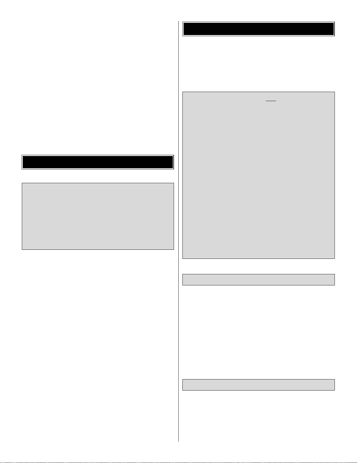
ElectriFly™FlatOuts™HellCat
Enjoy solo sport flying or exciting combat with another flat fighter
– indoors or out! Made of lightweight, precolored foam, the
FlatOuts Hellcat indoor ARF demands little time, effort or
expense – and its a perfect way to use your .40 glow trainer
experience to learn indoor piloting skills.The Hellcat has a low
parts count and factory-applied trim scheme, so you can have
your Hellcat flight-ready in as little as 1 to 2 hours. Precut slots
in the foam panels are ready for easy installation of linkages and
radio gear. The wing has a Jedelsky-type airfoil design to
improve lift and slow flight characteristics.It also incorporates a
round carbon-fiber spar to keep weight low and increase
strength. Includes prop, prop saver/adapter, streamers, and
factory-installed motor and gearbox.GPMA1121
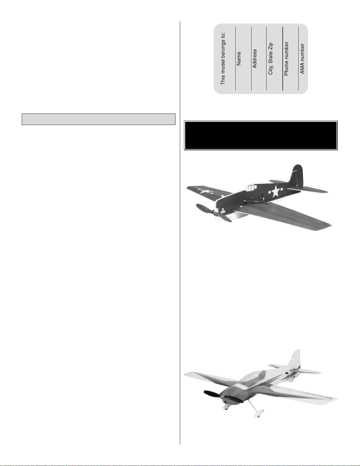
ElectriFly Reactor™3D EP ARF
With its generous wingspan, the Reactor 3D electric ARF is
easy to handle and track indoors or out.The wing’s ultra-thin
OTHER ITEMS AVAILABLE
FROM GREAT PLANES
Landing
14
Page 15
airfoil allows radical attitude changes and gentle handling on
approach. Oversized ailerons, adjustable pushrods and
short, direct linkages combine for crisp, powerful response.
The structure is factory-built from interlocking, laser-cut
balsa parts, with covering already applied, and the
fiberglass cowl and plastic wheel pants are painted to
match. Magnetic “latches” on the cowl and battery hatch
eliminate the need for screw fasteners and offer clean looks
and improved aerodynamics. Unlike most electrics, the
Reactor 3D ARF was designed for in-runner or out-runner
motors and includes mounts for both. GPMA1540
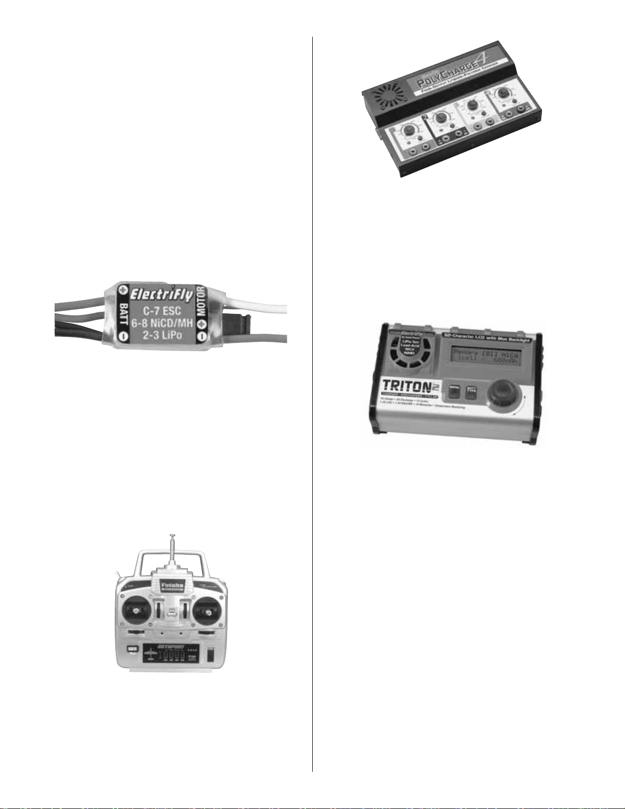
ElectriFly C-7 Nano Brushed ESC
The compact, easy-to-use C-7 Nano ESC is LiPo/NiCd/NiMH
compatible and offers BEC, fully proportional forward, factoryinstalled connectors, “Saf e Start”system and low voltage cut-off,
plus audible tones for easy set-up.GPMM2005
Futaba®4YF SkySport FM Radio
With its two 0.27 oz [7.7g] S3110 micro servos, the 4YF FM
is an ideal system for the FlatOuts J-3 Cub. In addition to
servo reversing and trims, the 4YF also includes an R114F
single-conversion receiver, charger, battery LEDs, and
sticks with length and tension adjustments. One additional
S3110 servo will be required. FUTJ36**
ElectriFly PolyCharge4
™
For convenience with multiple LiPo packs, there’s the DC
PolyCharge4. Each of its four independent outputs can
charge a one-to-four cell Lithium-Polymer pack. It’s ideal if
you don’t have the time for one-at-a-time charging – and
don’t want the expense and hassle of multiple chargers.
Each output can handle packs from 300 to 3000mAh. Set
the capacity, and PolyCharge4 will automatically set the
charge rate to get you started – and use light and sound
cues to tell you when your pack is done. GPMM3015
ElectriFly Triton™2 DC Computerized Peak Charger,
Discharger & Cycler
Like the popular original Triton charger, the Triton2 offers easy
programming. But the adjustable charge current has been
increased from 5.0A maximum to 7.0A, and the Triton2 can
handle LiPo packs with up to 5 cells in series. A cool blue
backlight on the 2 x 16 LCD screen makes for easier reading
in any conditions, and the rotating dial has been raised for
enhanced feel and more precise fingertip control. The Triton2
is more versatile too: you get alligator clips that mate onto the
banana plugs, for quick connection to 12V batteries or power
supplies.You’ll still be able to charge 1 to 4 cell lithium-ion and
lithium-polymer batteries, and peak 1 to 24 cell NiCd and
NiMH packs at rates you set to peak detection values you
choose – before discharging them at custom rates and then
repeating the cycle up to 10 times. GPMM3153
15
Page 16

BUILDING NOTES
Kit Purchased Date: _______________________
Where Purchased: _________________________
Date Construction Started: __________________
Date Construction Finished: _________________
Finished Weight: __________________________
Date of First Flight: ________________________
FLIGHT LOG
 Loading...