

Great Planes GPMA1117 User Manual
WARRANTY
Great Planes
®
Model Manufacturing Co. guarantees this kit to be free from defects in both material and workmanship at the date of
purchase.This warranty does not cover any component parts damaged by use or modification. In no case shall Great Planes’ liability
exceed the original cost of the purchased kit. Further, Great Planes reserves the right to change or modify this warranty without notice.
In that Great Planes has no control over the final assembly or material used for final assembly, no liability shall be assumed nor
accepted for any damage resulting from the use by the user of the final user-assemb led product.By the act of using the user-assembled
product, the user accepts all resulting liability.
If the buyer is not prepared to accept the liability associated with the use of this product, the buyer is advised to return this
kit immediately in new and unused condition to the place of purchase.
To make a warranty claim send the defective part or item to Hobby Services at the address below:
Hobby Services
3002 N. Apollo Dr., Suite 1
Champaign, IL 61822 USA
Include a letter stating your name, return shipping address, as much contact information as possible (daytime telephone number, fax
number, e-mail address), a detailed description of the problem and a photocopy of the purchase receipt. Upon receipt of the package
the problem will be evaluated as quickly as possible.
READ THROUGH THIS MANUAL BEFORE STARTING
CONSTRUCTION. IT CONTAINS IMPORTANT WARNINGS
AND INSTRUCTIONS CONCERNING THE ASSEMBLY
AND USE OF THIS MODEL.
GPMZ0183 for GPMA1117 V1.1Entire Contents © Copyright 2006
Champaign, Illinois
(217) 398-8970, Ext 5
airsupport@greatplanes.com
INSTRUCTION MANUAL
Wingspan: 31 in [780 mm]
Wing Area: 420 sq in [27dm2]
Weight: 10 – 12 oz [285 – 340g]
Wing Loading: 3.9 oz/sq ft [10 – 12g/dm2]
Length: 34 in [850 mm]
Radio: 4-channel w/3 micro servos and 8-Amp Brushless ESC
Power System: Direct-drive RimFire™Brushless motor (not included)
By Great Planes

2
INTRODUCTION ...............................................................2
SAFETY PRECAUTIONS..................................................2
LITHIUM BATTERY HANDLING & USAGE.....................3
DECISIONS YOU MUST MAKE........................................3
Motor ...........................................................................3
Transmitter...................................................................3
Servos .........................................................................3
Receiver ......................................................................4
Battery.........................................................................4
Speed Control .............................................................4
Charger .......................................................................4
Battery Charging Leads ..............................................4
Propeller Selection......................................................4
Glue.............................................................................4
ADDITIONAL ITEMS REQUIRED.....................................4
Adhesives & Building Supplies....................................4
ORDERING REPLACEMENT PARTS ..............................5
COMMON ABBREVIATIONS............................................5
METRIC CONVERSIONS .................................................5
KIT INSPECTION..............................................................6
KIT CONTENTS ................................................................6
BUILDING INSTRUCTIONS..............................................7
Assemble the Horizontal Tail .......................................7
Assemble the Fuselage...............................................8
Finish the Fuselage...................................................10
Assemble the Wing....................................................11
Connect the Rod Struts .............................................12
Finish the Wings........................................................13
Assemble the Landing Gear......................................14
Install the Servos.......................................................15
Install the Motor System............................................16
GET THE MODEL READY TO FLY .................................17
Check the Control Directions ....................................17
Set the Control Throws..............................................18
Balance the Model (C.G.)..........................................18
Balance the Model Laterally ......................................19
PREFLIGHT.....................................................................19
Identify Your Model....................................................19
Charge the Batteries .................................................19
Balance the Propellers..............................................19
Range Check.............................................................19
MOTOR SAFETY PRECAUTIONS .................................19
AMA SAFETY CODE (excerpts)....................................20
General......................................................................20
Radio Control ............................................................20
CHECK LIST ...................................................................20
FLYING ............................................................................20
Hand Launch.............................................................20
Rise-Off-Ground (ROG) Takeoffs ..............................21
Flight..........................................................................21
Landing......................................................................21
ANGLE TEMPLA TES......................................................23
The ElectriFly
™
by Great Planes FlatOuts R/C Universe Bipe
is an excellent way to enjoy 3D aerobatics without the cost
and headaches of giant-scale gasoline-powered models.
Four to six hours on the workbench, and your R/C Universe
Bipe will be ready to tackle torque rolls, walls, harriers, highalpha rolling circles and more! An excellent indoor or calmday outdoor performer, this airplane is a virtually unlimited
3D aerobat, but flying it involves only connecting the battery,
throttling up, and letting go!
Take care to build straight and true.Misaligned parts will hurt
the airplane’s ability to perform the extreme aerobatics it is
designed for.
For the latest technical updates or manual corrections to the
FlatOuts R/C Universe Bipe, visit the Great Planes web site
at www.greatplanes.com. Open the “Airplanes” link, and
then select the FlatOuts R/C Universe Bipe ARF. If there is
new technical information or changes to this model, a “tech
notice” box will appear in the upper left corner of the page.
Attention:The product you have purchased is
powered by a rechargeable battery. At the end
of its useful life, under various state and local
laws, it may be illegal to dispose of this battery
into the municipal waste system. Check with
your local solid waste officials for details in your area for
recycling options or proper disposal.
This product contains a chemical known to the state of
California to cause cancer and birth defects or other
reproductive harm.
1. Even though the FlatOuts R/C Universe Bipe is small,
lightweight and flies slowly, if it is not assembled and
operated correctly it could possibly cause injury to yourself
or spectators and damage property.
PRO TECT YOUR MODEL,Y OURSELF
& OTHERS...FOLLOW THESE
IMPORTANT SAFETY PRECAUTIONS
CAUTION: Be aware that the FlatOuts R/C Universe Bipe is
operated on the same frequency band as larger, “regular”
R/C models.If flying your R/C Universe Bipe within five miles
of an R/C site, there is a real possibility that you could be
operating your model on the same frequency (channel) as
another R/C pilot.If this happens a crash will result–with the
person flying the more expensive model suffering the
greater loss (and having greater potential for property
damage or injury).The best thing to do is to join an R/C club
and fly at the site where frequency control measures will be
in effect.If you insist on flying elsewhere, always be aware
of your proximity to R/C flying sites.
INTRODUCTIONTABLE OF CONTENTS

2. Build the plane according to the instructions. Do not
alter or modify the model, as doing so may result in an
unsafe or unflyable model.
3.Use an R/C radio system and components that are in firstclass condition. The FlatOuts R/C Universe Bipe requires
specialized radio gear. Refer to
“DECISIONS YOU MUST
MAKE”
to get an accurate description of the specialized
gear required.
4.You must properly install all R/C and other components so
that the model operates correctly on the ground and in the air .
5. You must test the operation of the model before every
flight to insure that all equipment is operating, and that the
model has remained structurally sound. Be sure to check
connectors often and replace them if they show signs of
wear or fatigue.
Remember:Take your time and follow directions to end
up with a well-built model that is straight and true.
If you’re not already an AMA (Academy of Model
Aeronautics) member, we highly recommend that you join.
In addition to providing liability protection while operating
under the AMA Safety Code, the AMA is the governing body
of model aeronautics in the United States and fights for your
rights as member of the modeling community.You must also
be an AMA member to fly at R/C clubs chartered by the
AMA–most of which are.Contact the AMA at the address or
toll-free phone number below.
WARNING!! Failure to follow all instructions could cause
permanent damage to the battery and its surroundings, and
cause bodily harm!
• ONLY use a LiPo approved charger. NEVER use a
NiCd/NiMH peak charger!
• NEVER charge in excess of 4.20V per cell.
• ONLY charge through the “charge” lead. NEVER charge
through the “discharge” lead.
• NEVER charge at currents greater than 1C.
• ALWAYS set charger’ s output v olts to match battery volts.
• ALWAYS charge in a fireproof location.
• NEVER trickle charge.
• NEVER allow the battery temperature to exceed
50°F (65°C).
• NEVER disassemble or modify pack wiring in any way or
puncture cells.
• NEVER discharge below 2.5V per cell.
• NEVER place on combustible materials or leave
unattended during charge or discharge.
• ALWAYS KEEP OUT OF REACH OF CHILDREN.
In the hands of a capable pilot, the FlatOuts R/C Universe
Bipe is an impressive 3D performer .But for the R/C Universe
Bipe to perform to its full potential, it must be properly
equipped with all the right gear (servos, batteries, receiver,
speed control).There may be more than one type and brand
of radio equipment that can be used, but based on extensiv e
testing, following is the equipment we recommend so you
can get the most performance out of your R/C Universe Bipe
and assemble it as shown in this instruction manual.
The FlatOuts R/C Universe Bipe performs extremely well
with the Great Planes RimFire™22M-1000 Brushless Motor
(GPMG4500) and it is the recommended motor for this
airplane. This manual covers the installation of the RimFire
motor and the plywood firewall included is designed
specifically for use with the RimFire. Other motors can be
used, however modification may be required for installation.
With a standard, four-channel radio, the FlatOuts R/C
Universe Bipe is capable of all the basic 3D maneuvers.
However, some advanced pilots who are already familiar
with handling “flat foamies” may prefer to fly this FlatOuts
with a computer radio capable of endpoint adjustments (for
fine-tuning control throws), exponentials (for “softening” the
throws near the center of the travel), and various mixing
functions (such as rudder-to-elevator mixing for extended
knife-edge flight).
The FlatOuts R/C Universe Bipe requires three
micro
servos
with a maximum weight of 9g [.3 oz] each and a minimum
torque rating of 15 oz-in. Futaba®S3108 servos
Servos
Transmitter
Motor
DECISIONS YOU MUST MAKE
LITHIUM BATTERY HANDLING & USAGE
Academy of Model Aeronautics
5151 East Memorial Drive
Muncie, IN 47302
Tele: (800) 435-9262
Fax (765) 741-0057
Or via the Internet at:
http://www.modelaircraft.org
Note: We, as the kit manufacturer, provide you with a top
quality kit and great instructions, but ultimately the quality
and flyability of your finished model depends on how you
build it; therefore, we cannot in any way guarantee the
performance of your completed model, and no
representations are expressed or implied as to the
performance or safety of your completed model.
3

(FUTM0042) are ideal because they meet the torque and
weight requirements. Although there may be other servos
that will physically fit in the model, those outside the
recommended weight and torque specifications will
adversely affect flight performance and are not
recommended. Note: During assembly when it’s time to
mount the servos, you will be instructed to glue them in. Do
not be alarmed as this is a common practice with this type
of lightweight, high-performance model. Should servo
removal ever be necessary for repair, replacement or
transfer to another model, this can be done by prying them
out with a hobby knife or a small screwdriver.
A light, four-channel receiver is recommended and must be
compatible with whatever servos will be used (not all servos
are compatible with all receivers–even servos and receivers
within the same brand).The Futaba R-114F
Micro
receiver is
recommended and is compatible with the S3108 servos
recommended. Note: Futaba receivers are sold on high and
low bands and come without crystals. Following are the order
numbers for the R-114F receiver and compatible crystals:
Low Band High Band
(Channels 11-35) (Channels 36-60)
R124F Receiver FUTL0438 FUTL0439
Crystal FUTL62** FUTL63**
**Replace the “**” in the order number for the crystals with
the preferred channel number .For example, if you w ant to fly
on channel 33, order a low band receiver and crystal
number FUTL6233.
The FlatOuts R/C Universe Bipe requires a 3-cell (11.1V),
350–700mAh lithium-polymer (LiPo) battery capable of
providing 7A continuous discharge current. The ElectriFly
3-cell,
3-Series
640mAh battery pack is recommended
(GPMP0805). Note: The ElectriFly 720mAh battery is not
recommended for this model as it is not capable of
delivering the current required by this system. For optimum
performance, battery weight should not exceed 54g [2 oz.].
An electronic speed control capable of handling a minimum
of 8A continuous current is required. Additionally, the speed
control should be as light as possible. The ElectriFly BL-8
Micro Brushless ESC w/BEC (GPMM2070) or the Electrifly
Silver Series 8A Brushless ESC w/BEC (GPMM1800) are
suitable. NEVER use speed controllers intended for
brushed motors on brushless motors.
A charger capable of charging 3-cell (11.1V) LiPo batteries
such as the ElectriFly PolyCharge 1 to 3-cell LiPo charger
(GPMM3010) must be used. If using another charger, it
must be a LiPo charger or have a LiPo charge mode. Never
charge LiPo batteries with chargers not intended for LiPo
batteries or chargers on NiMH or NiCd settings.
Overcharging or explosion may result. In addition to the
PolyCharge, the ElectriFly Triton™(GPMM3150) or AccuCycle Elite™(HCAP0280) are also suitable chargers.
Many chargers (including the Triton and Accu-Cycle Elite
listed above) do not include charging leads, but rather have
banana jacks to plug the leads into. If this is the case with
your charger, you will need to purchase a charge lead to
match your battery. For the recommended 640mAh pack,
the correct lead is GPMM3105.
The Great Planes 9x3.5S (GPMQ6625) propeller offers very
good performance with the Great Planes RimFire motor system.
A Great Planes 10x3.5 (GPMQ6655) propeller will also offer
good performance.
Though there may be a few different types of adhesives that
the FlatOuts R/C Universe Bipe could be assembled with, we
have had the best success with and exclusively recommend,
foam-safe CA such as Great Planes 1 oz.thick, foam-safe CA
(GPMR6072).Thin, foam-safe CA such as Hot Stuff UFO thin
CA (HOTR1040) is also used in the construction of this model.
Regular CA is not recommended as it will aggressively attack
the foam used in this model. In addition to being foamcompatible, foam-saf e CA is also suitable f or gluing together all
of the rest of the materials (balsa, carbon) included in this kit.
No other adhesive is required to build the FlatOuts R/C
Universe Bipe.
In addition to common household tools and hobby tools, this
is the “short list”of the most important items required to build
the FlatOuts R/C Universe Bipe:
❏ Great Planes Aerosol Activator (GPMR6034)
❏ Hobbico
®
CA Applicator tips (HCAR3780)
❏ Hobby knife with #11 blade (HCAR0100)
Adhesives & Building Supplies
ADDITIONAL ITEMS REQUIRED
Glue
Propeller Selection
Battery Charging Leads
Charger
Speed Control
Battery
Receiver
4

❏ #11 blades (5-pack – HCAR0211)
❏ 1-meter metric ruler (for identifying tubes and rods)
❏ 5-1/2" [140 mm] Easy-Touch
™
bar sander (GPMR6169)
with 220-grit sandpaper (GPMR6185)
❏ Drill bits: 1/16" [1.5 mm], 3/32" [2.5 mm]
❏ Double-sided foam tape (GPMQ4400)
❏ Stick-on weight (GPMQ4485)
❏ Great Planes Plan Protector
™
(GPMR6167) or wax paper
Replacement parts for the Great Planes FlatOuts R/C
Universe Bipe ARF are av ailab le using the order n umbers in
the Replacement Parts List that follows.The fastest, most
economical service can be provided by your hobby dealer or
mail-order company.
To locate a hobby dealer, visit the Hobbico web site at
www.hobbico.com. Choose “Where to Buy” at the bottom of
the menu on the left side of the page. Follow the instructions
provided on the page to locate a U.S ., Canadian or International
dealer.If a hobby shop is not av ailable, replacement parts may also
be ordered from Tower Hobbies®at www.towerhobbies.com,
or by calling toll free (800) 637-6050.
Parts may also be ordered directly from Hobby Services by
calling (217) 398-0007, or via facsimile at (217) 398-7721,
but full retail prices and shipping and handling charges will
apply. Illinois and Nevada residents will also be charged
sales tax. If order ing via fax, include a Visa®or MasterCard
®
number and expiration date for payment.
Mail parts orders and payments by personal check to:
Hobby Services
3002 N. Apollo Drive, Suite 1
Champaign, IL 61822
Be certain to specify the order number exactly as listed in
the Replacement Parts List. Payment by credit card or
personal check only; no C.O.D.
If additional assistance is required for any reason contact Product
Support by e-mail at productsupport@greatplanes.com, or
by telephone at (217) 398-8970.
Replacement Parts List
Order Number Description How to Purchase
Missing pieces Contact Product Support
Instruction manual Contact Product Support
Full-size plans Not available
GPMQ6625 9x3.5S Propeller Contact Hobby Supplier
GPMQ4618 Prop Saver O-ring Contact Hobby Supplier
GPMQ4620 Prop Saver Contact Hobby Supplier
Fuse = Fuselage
Stab = Horizontal Stabilizer
Fin = Ver tical Fin
LE = Leading Edge
TE = Trailing Edge
LG = Landing Gear
Ply = Plywood
" = Inches
mm = Millimeters
SHCS = Socket Head Cap Screw
1" = 25.4 mm (conversion factor)
METRIC CONVERSIONS
COMMON ABBREVIATIONS
ORDERING REPLACEMENT PARTS
5
1/64" = .4 mm
1/32" = .8 mm
1/16" = 1.6 mm
3/32" = 2.4 mm
1/8" = 3.2 mm
5/32" = 4.0 mm
3/16" = 4.8 mm
1/4" = 6.4 mm
3/8" = 9.5 mm
1/2" = 12.7 mm
5/8" = 15.9 mm
3/4" = 19.0 mm
1" = 25.4 mm
2" = 50.8 mm
3" = 76.2 mm
6" = 152.4 mm
12" = 304.8 mm
18" = 457.2 mm
21" = 533.4 mm
24" = 609.6 mm
30" = 762.0 mm
36" = 914.4 mm
6
Before starting to build, take an inventory of this kit to make sure it is complete, and inspect the parts to make sure they
are of acceptable quality. If any parts are missing or are not of acceptable quality, or if you need assistance with assembly,
contact Product Support. When repor ting defective or missing parts, use the part names exactly as they are written in
the Kit Contents list.
Great Planes Product Support:
3002 N. Apollo Drive, Suite 1
Champaign, IL 61822
Telephone: (217) 398-8970, ext. 5
Fax: (217) 398-7721
E-mail:
airsupport@greatplanes.com
KIT INSPECTION
Plastic Tree Parts
A1 Z-Bend Clevis (10)
A2 Offset Z-Bend Clevis (4)
B1 Stand-Alone Control Horn (5)
B2 Stand-Alone Control Horn Retainer (5)
C1 Clip Hinge Control Horn (5)
C2 Clip Hinge (26)
C3 Hinge Retainer Ring (10)
C4 Aileron Link Horn (4)
D1 Axle Support (2)
D2 Rod Support (12)
D4 Tailwheel Bracket (1)
D5 Tailwheel (1)
D6 Wheel Collar (2)
E1 Control Surface Brace (4)
E2 Fuselage Joiner (3)
E3 Pushrod Suppor t (4)
F1 Wire Clip (4)
F2 Aileron Servo Mounting Tray (1)
F3 Fuselage Servo Mount (2)
F4 Fuselage Aileron Servo Mount (1)
G1 Double-Sided Offset Arm, Size B (2)
G2 Double-Sided Arm, Size B (2)
G3 Single-Sided Arm, Size B (4)
G4 Double-Sided Arm, Size A (2)
G5 Double-Sided Offset Arm, Size A (2)
G6 Single-Sided Arm, Size A (4)
G7 Double-Sided Arm, Size C (2)
G8 Double-Sided Offset Arm, Size C (2)
G9 Single-Aided Arm, Size C (4)
Carbon Rods & Tubes
Fuselage Doubler Tube 5.5 x 295 mm
Elevator Joiner Tube 3 x 216 mm
Rudder Post Tube 3 x 145 mm
Fuselage Main Tube 3 x 684 mm
Leading Edge Tube 3 x 650 mm (2)
Trailing Edge Tube 3 x 370 mm (4)
Landing Gear Rods 2 x 190 mm (2)
Wheel Axles 2 x 17 mm (2)
Rudder Pushrod 1 x 340 mm
Elevator Pushrod 1 x 370 mm
Aileron Pushrod 1 x 80 mm (2)
Aileron Link Pushrod 1 x 165 mm (2)
Other Parts
Firewall
O-rings
Top Wing Braces 2 x 115 mm (4)
Bottom Wing Braces 2 x 85 mm (2)
Kit Contents (Not Photographed)
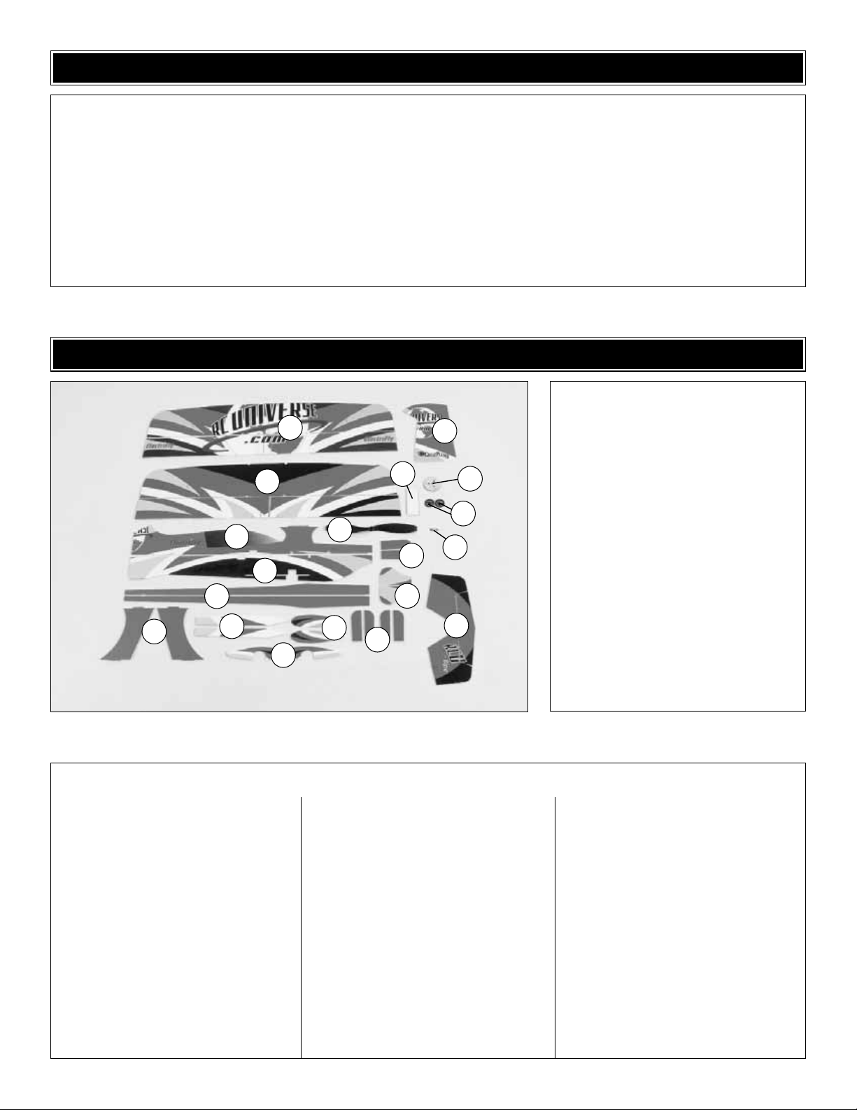
KIT CONTENTS
Kit Contents
1. Top Wing & Ailerons
2. Bottom Wing & Ailerons
3. Rudder
4. Plywood Firewall
5. Main Wheels
6. Hook and Loop Material
7. Upper Ver tical Fuselage Half
8. Lower Vertical Fuselage Half
9. Propeller
10. Small Vertical Nose Doublers (2)
11. Prop Saver
12. Horizontal Fuselage Halves (L&R)
13. Interplane Struts (L&R)
14. Fuselage Braces (L&R)
15. Inner Wheel Pants (L&R)
16. Outer Wheel Pants (L&R)
17. Horizontal Nose Doublers (4)
18. Large Vertical Nose Doublers (2)
19. Horizontal Stabilizer w/Elevators
1
3
7
8
9
10
2
5
4
6
11
12
13
14
16
17
19
18
15
Please note that all of the plastic parts used when building
the FlatOuts R/C Universe Bipe are identified by name and
part number, for example: Z-bend clevis (A1). The part
numbers are molded next to each part on the parts trees for
easy identification.
The carbon tube diameters referenced throughout this
manual may be difficult to measure without calipers. The
dimensions provided consist of 1 mm, 2 mm, 3 mm, and 5.5
mm.These four sizes can be identified by comparing all the
tubes next to each other. Once the diameters are
determined, it is advisable to group the tubes together by
size for quick reference.
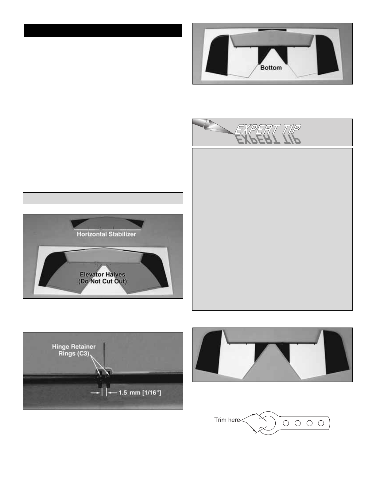
❏ 1. Cut the horizontal stabilizer free from the foam sheet
using a hobby knife with a sharp #11 blade.DO NOT cut the
elevator halves free at this time.
❏ 2. Without removing the elevator halves from the foam
sheet, slide two hinge retainer rings (C3) onto the elevator
joiner tube.Align the rings with the cutout in the left elevator
half.The ring on the right should be in line with the edge of
the cutout and there should be a 1.5 mm [1/16"] gap
between the two rings. Secure both rings to the tube with a
drop of glue on the outside of the gap.
❏ 3. Using the
Expert Tip
that follows, permanently join the
elevator halves by gluing in the 3 x 216 mm [1/8" x 8-1/2"]
elevator joiner tube.
❏ 4. Now the elevator halves may be cut from the sheet.
❏ 5.To avoid broken clip hinges (C2) and control horns (C1)
during assembly, tr im them as shown before installing onto
the 3mm carbon tubes.
HOW T O GLUE THE TUBES TO
THE CONTROL SURFACES
Note: You may want to protect your work surface from
excess glue.We recommend the use of Great Planes Plan
Protector™(GPMR6167) for this purpose.
A. Cut several 40 mm [1-1/2"] pieces of cellophane tape.Fold
the last 5 mm [1/4"] over to make a tab for easy removal.
B. Lightly coat the leading edges of the elevators with
foam-safe CA–do not use an excessive amount. Hint: A
CA applicator tip is recommended to accurately control
the bead of glue.
C. Tape the tube to the leading edge of the elevators.
Weight the assembly down on a flat surface to prevent
warping and allow the glue to harden without accelerator.
D. Once the glue has hardened, remove the tape.
E. Add a fillet of glue to the bottom of the joiner tube
and elevators.
Assemble the Horizontal Tail
BUILDING INSTRUCTIONS
7
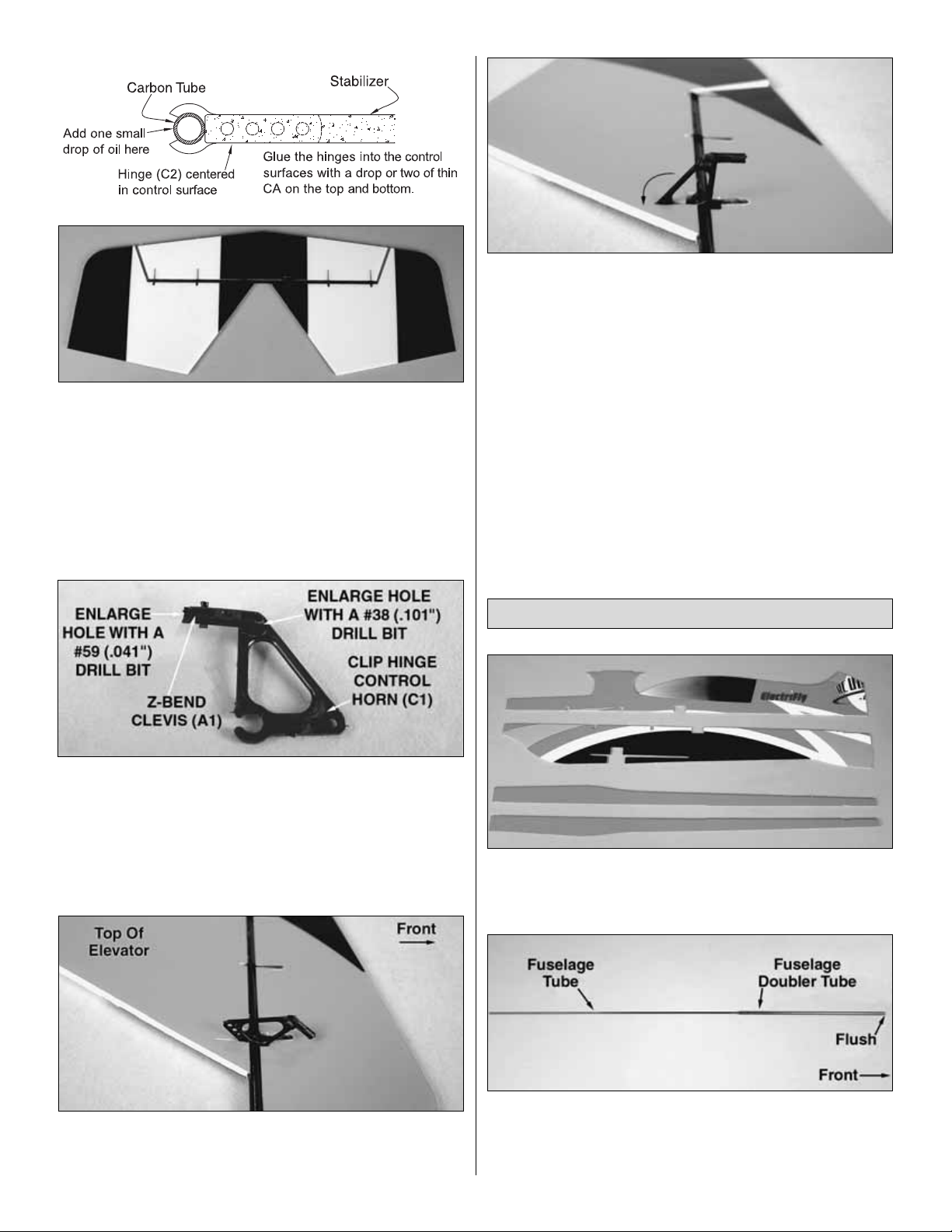
❏ 6.Snap all the clip hinges to the carbon tube already glued
to the elevators .Push the hinges into the slots in the stabilizer.
Make sure the hinges are centered in the stabilizer .Add a drop
of oil to each hinge. Glue the hinges into the stabilizer with a
drop or two of foam-safe thin CA (Hot Stuff UFO Thin FoamSafe 1 oz, HOTR1040) where shown.
❏ 7. Enlarge the hole in the Z-bend clevis (A1) with a #59
(.041") drill bit. Enlarge the hole in a clip-hinge control horn
(C1) with a #38 (.101") drill bit. Insert the Z-bend clevis (A1)
into the clip-hinge control horn (C1) as shown.
❏ 8. Clip the control horn onto the joiner tube aligned with
the precut slot.The control horn must extend above the top
of the elevator.
❏ 9. Coat the gluing area on the control horn with thick,
foam-safe CA glue and rotate it down into the precut slot.
❏ 1. Cut the upper and lower vertical fuselage halves
and the left and right horizontal fuselage halves free from
their foam sheets.
❏ 2. Glue the 3 x 684 mm [1/8" x 26-15/16"] fuselage tube
into the 5.5 x 295 mm [7/32" x 11-5/8"] fuselage tube
doubler. One end should be flush. From now on, this
assembly will be referred to as the fuselage tube.
Assemble the Fuselage
8
 Loading...