

Page 1
WARRANTY
Great Planes
®
Model Manufacturing Co. guarantees this kit to be free from defects in both material and workmanship at the date of
purchase.This warranty does not cover any component parts damaged by use or modification. In no case shall Great Planes’liability
exceed the original cost of the purchased kit. Further, Great Planes reserves the right to change or modify this warranty without notice.
In that Great Planes has no control over the final assembly or material used for final assembly, no liability shall be assumed nor
accepted for any damage resulting from the use by the user of the final user-assemb led product.By the act of using the user-assembled
product, the user accepts all resulting liability.
If the buyer is not prepared to accept the liability associated with the use of this product, the buyer is advised to return this
kit immediately in new and unused condition to the place of purchase.
To make a warranty claim send the defective part or item to Hobby Services at the address below:
Hobby Services
3002 N. Apollo Dr., Suite 1
Champaign, IL 61822 USA
Include a letter stating your name, return shipping address, as much contact information as possible (daytime telephone number, fax
number, e-mail address), a detailed description of the problem and a photocopy of the purchase receipt. Upon receipt of the package
the problem will be evaluated as quickly as possible.
READ THROUGH THIS MANUAL BEFORE STARTING
CONSTRUCTION. IT CONTAINS IMPORTANT WARNINGS
AND INSTRUCTIONS CONCERNING THE ASSEMBLY
AND USE OF THIS MODEL.
GPMZ0172 for GPMA1113 V1.0© Copyright 2005
Champaign, Illinois
(217) 398-8970, Ext 5
INSTRUCTION MANUAL
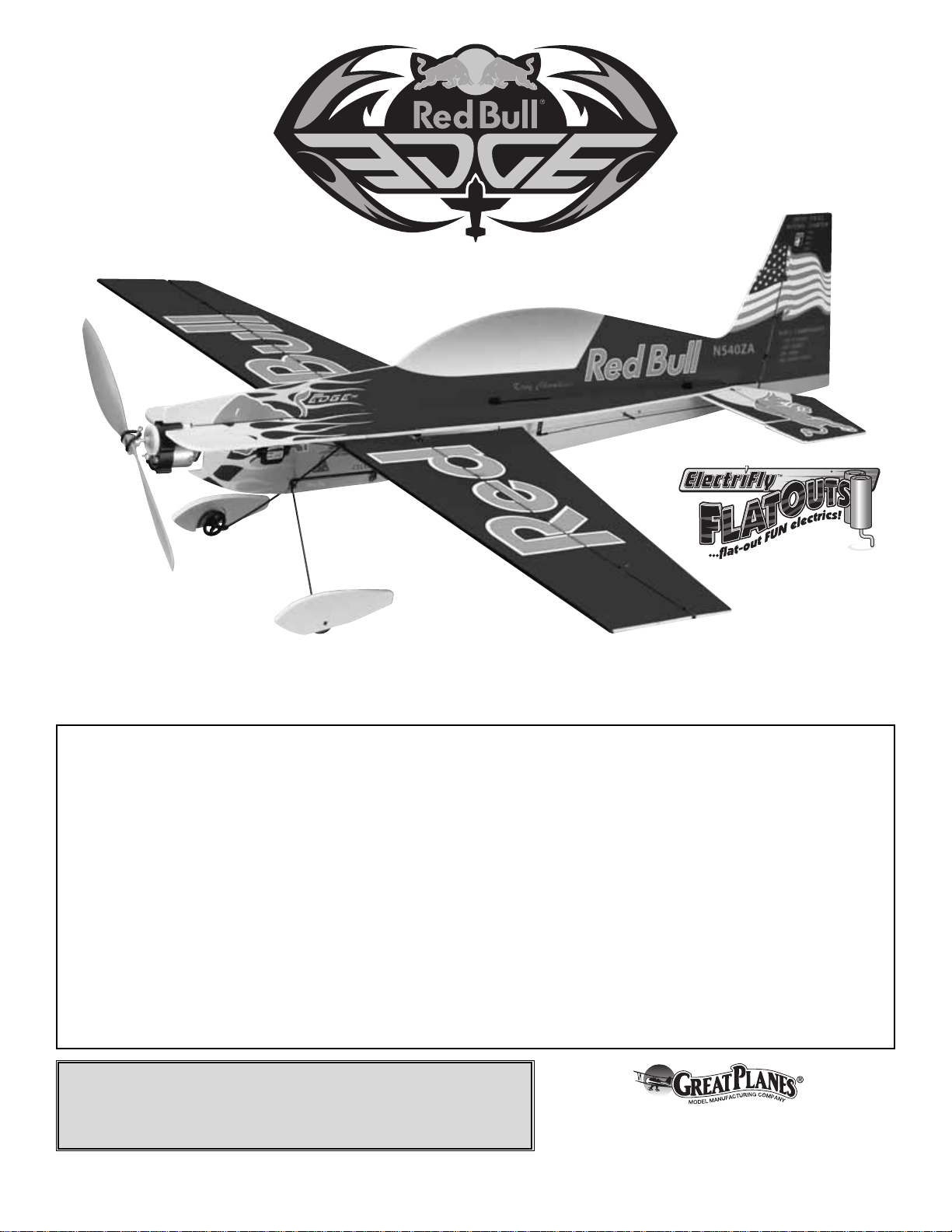
Wingspan: 35.5 in [900mm]
Wing Area: 208 sq in [13.4 dm2]
Wing Loading: 5.2 – 6.2 oz/sq ft
[16 – 19 g/dm2]
Weight: 7.5 – 9 oz [215-255 g]
Length: 33 in [840mm]
Radio: 4-channel w/3 micro servos and 10-Amp ESC
Power System: Included ElectriFly™motor with gearbox, or optional
direct-drive RimFire™Brushless motor
™
By Great Planes
Page 2
2
INTRODUCTION................................................................2
SAFETY PRECAUTIONS..................................................2
DECISIONS YOU MUST MAKE ........................................3
Transmitter ...................................................................3
Servos..........................................................................3
Receiver.......................................................................3
Battery .........................................................................4
Speed Control..............................................................4
Charger........................................................................4
Battery Charging Leads...............................................4
Optional: Brushless Motor Upgrade.............................4
Propeller Selection.......................................................4
Glue .............................................................................4
ADDITIONAL ITEMS REQUIRED.....................................4
KIT INSPECTION...............................................................5
KIT CONTENTS .................................................................5
ORDERING REPLACEMENT PARTS...............................6
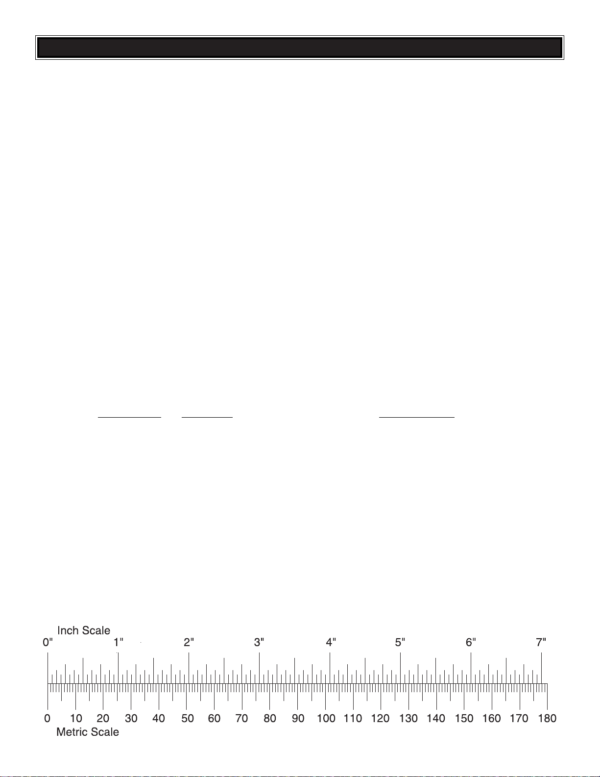
METRIC/INCH RULER ......................................................6
BUILD THE AIRPLANE.....................................................7
Assemble the Horizontal Tail........................................7
Assemble the Wing ......................................................9
Assemble the Fuselage...............................................9
Finish the Landing Gear............................................13
Radio Setup...............................................................13
Mount the Motor & Gearbox......................................15
Firewall-Mounted Motor System................................17
GET THE MODEL READY TO FLY..................................18
Check the Control Directions.....................................18
Set the Control Throws..............................................18
Balance the Model (C.G.)..........................................19
Balance the Model Laterally......................................19
PREFLIGHT.....................................................................19
Identify Your Model.....................................................19
Charge the Batteries ..................................................19
Range Check.............................................................20
MOTOR SAFETY PRECAUTIONS..................................20
AMA SAFETY CODE (excerpts)....................................20
CHECK LIST ....................................................................20
FLYING.............................................................................21
Hand Launch .............................................................21
Rise-Off-Ground (ROG) Takeoff.................................21
Flight..........................................................................21
Landing......................................................................21
The ElectriFly by Great Planes FlatOuts Edge 540 ARF is
an excellent wa y to enjo y 3D aerobatics without the cost and
headaches of giant-scale gasoline-powered models. After a
couple of hours on the workbench, your FlatOuts Edge 540
ARF will be ready to tackle torque rolls, walls, harriers, highalpha rolling circles and more! An excellent indoor or calmday outdoor performer, this airplane is a virtually unlimited
3D aerobat, but flying it involves only connecting the battery,
throttling up, and letting go!
Take care to build straight and true. Misaligned parts will
hurt the air plane’s ability to perform the extreme aerobatics
it is designed for.
For the latest technical updates or manual corrections to the
FlatOuts Edge 540 ARF visit the Great Planes web site at
www.electrifly.com
. Open the “Airplanes” link, then select
the FlatOuts Edge 540 ARF. If there is new technical
information or changes to this model, a “tech notice”box will
appear in the upper left corner of the page.
Attention: The product you have purchased is powered by
a rechargeable battery. At the end of its useful life, under
various state and local laws, it may be illegal
to dispose of this battery into the municipal
waste system. Check with your local solid
waste officials for details in your area for
recycling options or proper disposal. This
product contains a chemical known to the state of
California to cause cancer and birth defects or other
reproductive harm.
1. Even though the FlatOuts Edge 540 ARF is small,
lightweight and flies slowly, if it is not assembled and
operated correctly it could possibly cause injury to yourself
or spectators and damage property.
2. Build the plane according to the instructions. Do not
alter or modify the model, as doing so may result in an
unsafe or unflyable model.
PRO TECT YOUR MODEL,YOURSELF
& OTHERS...FOLLOW THESE
IMPORTANT SAFETY PRECAUTIONS
A NOTE ABOUT METRIC DIMENSIONS
Since the parts of this air plane have been designed with
metric dimensions, the metric size (in millimeters) of the
parts is listed first in the text. For convenience, we have
listed close approximations of these sizes in the English
system (inches), but be aware that these conversions are
only approximate.
CAUTION: Be aware that the FlatOuts Edge 540 ARF is
operated on the same frequency band as larger, “regular”
R/C models. If flying your FlatOuts Edge 540 ARF within
five miles of an R/C site, there is a real possibility that you
could be operating your model on the same frequency
(channel) as another R/C pilot.If this happens a crash will
result–with the person flying the more expensive model
suffering the greater loss (and having greater potential f or
property damage or injur y). The best thing to do is to join
an R/C club and fly at the site where frequency control
measures will be in effect.If you insist on flying elsewhere
always be aware of your proximity to R/C flying sites.
INTRODUCTION
TABLE OF CONTENTS
Page 3

3.Use an R/C radio system and components that are in firstclass condition. The FlatOuts Edge 540 ARF requires
specialized radio gear. Refer to the
“DECISIONS YOU
MUST MAKE”
section to get an accurate description of the
specialized gear required.
4.You must properly install all R/C and other components so
that the model operates correctly on the ground and in the air .
5. You must test the operation of the model before every
flight to insure that all equipment is operating, and that the
model has remained structurally sound. Be sure to check
connectors often and replace them if they show signs of
wear or fatigue.
Remember:Take your time and follow directions to end
up with a well-built model that is straight and true.
If you’re not already an AMA (Academy of Model
Aeronautics) member, we highly recommend that you join.
In addition to providing liability protection while operating
under the AMA Safety Code, the AMA is the governing body
of model aeronautics in the United States and fights for your
rights as a member of the modeling community. You must
also be an AMA member to fly at R/C clubs chartered by the
AMA–most of which are.
Contact the AMA at the address or toll-free phone
number below.
Academy of Model Aeronautics
5151 East Memorial Drive
Muncie, IN 47302
Tele: (800) 435-9262
Fax (765) 741-0057
Or via the Internet at:
www.modelaircraft.org
In the hands of a capable pilot the FlatOuts Edge 540 ARF is
an impressive 3D performer. But for the FlatOuts Edge 540
ARF to perform to its full potential, it must be properly
equipped with all the right gear (servos, batteries, receiver,
speed control).There may be more than one type and brand
of radio equipment that can be used, but based on extensive
testing, following is the equipment we recommend so you
can get the most performance out of your FlatOuts Edge 540
ARF and assemble it as shown in this instruction manual.
With a standard, four-channel radio, the FlatOuts Edge 540
ARF is capable of all the basic 3D maneuvers. However,
some advanced pilots who are already familiar with handling
“flat foamies” may prefer to fly the FlatOuts Edge 540 ARF
with a computer radio capable of endpoint adjustments (for
fine-tuning control throws), exponentials (for “softening” the
throws near the center of the travel), and various mixing
functions (such as rudder-to-elevator mixing for extended
knife-edge flight).
The FlatOuts Edge 540 ARF requires three,
sub-micro
servos with a maximum weight of .3 oz [9g] each and a
minimum torque rating of 15 oz-in. Futaba®S-3108M (micro
connector) servos (FUTM0700) are ideal because they meet
the torque and weight requirements and have a micro
connector that is compatible with the Futaba
Ultra Micro
receiver. Although there may be other servos that will
physically fit in the model, those outside of the recommended
weight and torque specifications will adversely affect flight
performance and are not recommended.
Note: Dur ing assembly when it’s time to mount the servos,
you will be instructed to glue them in. Do not be alarmed as
this is a common practice with this type of lightweight, highperformance model. Should servo removal ever be
necessary for repair, replacement or transfer to another
model, this can be done by prying them out with a hobby
knife or a small screwdriver.
The lightest, four-channel receiver is recommended and
must be compatible with whatever servos will be used (not
all servos are compatible with all receivers–e v en servos and
receivers within the same brand).The Futaba R-124F
Ultra
Micro
receiver is recommended and is compatible with the
3108M servos recommended. Note: Futaba receivers are
sold on high and low bands and come without crystals.
Following are the order numbers for the R-124F receiver
and compatible crystals:
Low Band High Band
(Channels 11-35) (Channels 36-60)
R124F Receiver FUTL0438 FUTL0439
Crystal FUTL62** FUTL63**
** Replace the “**” in the order number for the crystals with
the preferred channel number .For example, if you w ant to fly
on channel 33, order a low band receiver and crystal
number FUTL6233.
Receiver
Servos
Transmitter
DECISIONS YOU MUST MAKE
Note: We, as the kit manufacturer, provide you with a
top quality kit and great instructions, but ultimately the
quality and flyability of your finished model depends on
how you build it; therefore, we cannot in any way
guarantee the performance of your completed model, and
no representations are expressed or implied as to the
performance or safety of your completed model.
3
Page 4
The FlatOuts Edge 540 ARF requires a 3-cell (11.1V), 350700mAh lithium-polymer (Li-Po) battery capable of providing
7A continuous discharge current.For long flight times and good
performance, we recommend the ElectriFly 3-cell, 3-Series
640mAh battery pack (GPMP0805). For minimum weight, at
the expense of some flight time, the ElectriFly 3-cell, 3-Series
350mAh battery pack (GPMP0801) works well.
Note: The ElectriFly 720mAh battery is not recommended for
this model as it is not capable of delivering the current required
by this system. For optimum performance battery weight
should not exceed 2.3 oz.[65g].
An electronic speed control capable of handling a minimum of
7A continuous current is required. Additionally, the speed
control should be as light as possible. The ElectriFly C-10
Micro
High-Frequency ESC w/BEC (GPMM2010) is suitable .If
upgrading to the optional brushless motor system
recommended (below), a speed control intended for brushless
motors (a
brushless
speed control) capable of at least 8A
continuous current such as the ElectriFly BL-8 (GPMM2070)
must be used. NEVER use speed controllers intended for
brushed motors on brushless motors (and vice-versa).
A charger capable of charging 3-cell (11.1V) Li-Po batteries
such as the ElectriFly PolyCharge 1-3-cell Li-Po charger
(GPMM3010) must be used. If using another charger, it must
be a Li-Po charger or ha ve a Li-P o charge mode .Never charge
Li-Po batteries with chargers not intended for Li-Po batteries or
chargers on NiMH or NiCd settings.Overcharging or explosion
may result.In addition to the PolyCharge, the ElectriFly Triton
™
(GPMM3150) or Accu-Cycle™Elite (HCAP0280) are also
suitable chargers.
Many chargers (including the Triton and Accu-Cycle Elite
listed above) do not include charging leads, but rather have
banana jacks to plug the leads into. If this is the case with
your charger, you will need to purchase a charge lead to
match your battery. For the recommended 640mAh pack,
the correct lead is GPMM3105.
Rest assured, the FlatOuts Edge 540 ARF is capable of 3D
flight with the included ElectriFly “stick-mount” motor and
gearbox combination. But for pilots who always insist on
upgrading and don’t mind spending a little extra money, the
ElectriFly Rimfire 22M-1000 brushless motor (GPMG4500)
will provide increased power and flight time while
simultaneously reducing weight.Don’t forget, if upgrading to
a brushless motor, a “brushless” speed controller such as
the ElectriFly BL-8 8-Amp ESC (GPMM2070) must be
used. This kit also includes the firewall and instructions for
mounting a brushless motor.
A propeller is included in this kit, and this propeller offers the
best performance with the included motor system. If you are
upgrading to the RimFire brushless motor, a 9 x 3.8 propeller
is recommended.
Though there may be a few different types of adhesives that
the FlatOuts Edge 540 ARF could be assembled with, we
have had the best success with, and e xclusively recommend
foam-safe CA such as 1 oz.Great Planes Foam Safe Thic k CA
(GPMR6072). Regular CA is not recommended as it will
aggressively attack the foam used in this model. In addition
to being foam-compatible, foam-safe CA is also suitable for
gluing together all of the rest of the materials (balsa, carbon)
included in this kit.No other adhesive is required to build the
FlatOuts Edge 540 ARF.
In addition to common household tools and hobby tools, this
is the “short list”of the most important items required to build
the FlatOuts Edge 540 ARF.
Great Planes Pro™CA and
Epoxy glue are recommended.
❏ Two 200mm servo extensions (FUTM4508)
❏ Great Planes Aerosol Activator (GPMR6034)
❏ Hobbico
®
CA Applicator tips (HCAR3780)
❏ Hobby knife with #11 blade (HCAR0100)
❏ #11 Blades (5-pack: HCAR0211)
❏ 1m Metric r uler (for identifying tubes and rods)
❏ 5-1/2" [140mm] Easy-Touch
™
bar sander (GPMR6169)
with 220-grit Sandpaper (GPMR6185)
❏ Drill bits: 1/16" [1.5mm], 3/32" [2.5mm]
❏ Double-sided foam tape (GPMQ4400)
❏ 1/2" [13mm]-wide Cellophane tape
❏ Great Planes Plan Protector
™
(GPMR6167) or wax paper
ADDITIONAL ITEMS REQUIRED
Glue
Propeller Selection
Optional: Brushless Motor Upgrade
Battery Charging Leads
Charger
Speed Control
Battery
4
Page 5
5
Before starting to build, take an inventory of this kit to make sure it is complete, and inspect the parts to make sure they
are of acceptable quality. If any parts are missing or are not of acceptable quality , or if y ou need assistance with assemb ly,
contact Product Support. When repor ting defective or missing parts, use the part names exactly as they are written in
the Kit Contents list.
Great Planes Product Support:
3002 N. Apollo Drive, Suite 1
Champaign, IL 61822
Telephone: (217) 398-8970, ext. 5
Fax: (217) 398-7721
E-mail:
KIT INSPECTION
Plastic Tree Parts
A1 Z-Bend Clevis (10)
A2 Offset Z-Bend Clevis (4)
B1 Stand-Alone Control Horn (5)
B2 Stand-Alone Control Horn Retainer (5)
C1 Clip Hinge Control Horn (5)
C2 Clip Hinge (26)
C3 Hinge Retainer Ring (10)
C4 Aileron Link Horn (4)
D1 Axle Support (2)
D2 Rod Support (12)
D4 Tailwheel Bracket (1)
D5 Tailwheel (1)
D6 Wheel Collar (2)
E1 Control Surface Brace (4)
E2 Fuselage Joiner (3)
E3 Pushrod Guides (4)
F1 Wire Clip (4)
F2 Wing Servo Mount (1)
F3 Fuselage Servo Mount (2)
F4 Fuselage Aileron Servo Mount (1)
G1 Double-Sided Offset Arm, Size B (2)
G2 Double-Sided Arm, Size B (2)
G3 Single-Sided Arm, Size B (4)
G4 Double-Sided Arm, Size A (2)
G5 Double-Sided Offset Arm, Size A (2)
G6 Single-Sided Arm, Size A (4)
G7 Double-Sided Arm, Size C (2)
G8 Double-Sided Offset Arm, Size C (2)
G9 Single-Sided Arm, Size C (4)
Carbon Rods & Tubes
Fuselage Doubler Tube 5.5 x 142mm
Elevator Joiner Tube 3 x 208mm
Rudder Post Tube 3 x 154mm
Fuselage Main Tube 3 x 715mm
Landing Gear Brace Tube 3 x 90mm
Leading Edge Tube 3 x 900mm
Trailing Edge Tube 3 x 900mm
Landing Gear Legs 2 x 195mm (2)
Rear Wing Struts 2 x 94mm (2)
Wheel Axles 2 x 17mm (2)
Rudder Pushrod 1 x 315mm
Elevator Pushrod 1 x 305mm
Aileron Pushrods 1 x 117mm (2)
Misc. Parts
3mm Plywood Firewall
Prop Saver
Prop Saver O-Rings
Hardwood Motor Mount Stick
Kit Contents (Not Photographed)
KIT CONTENTS
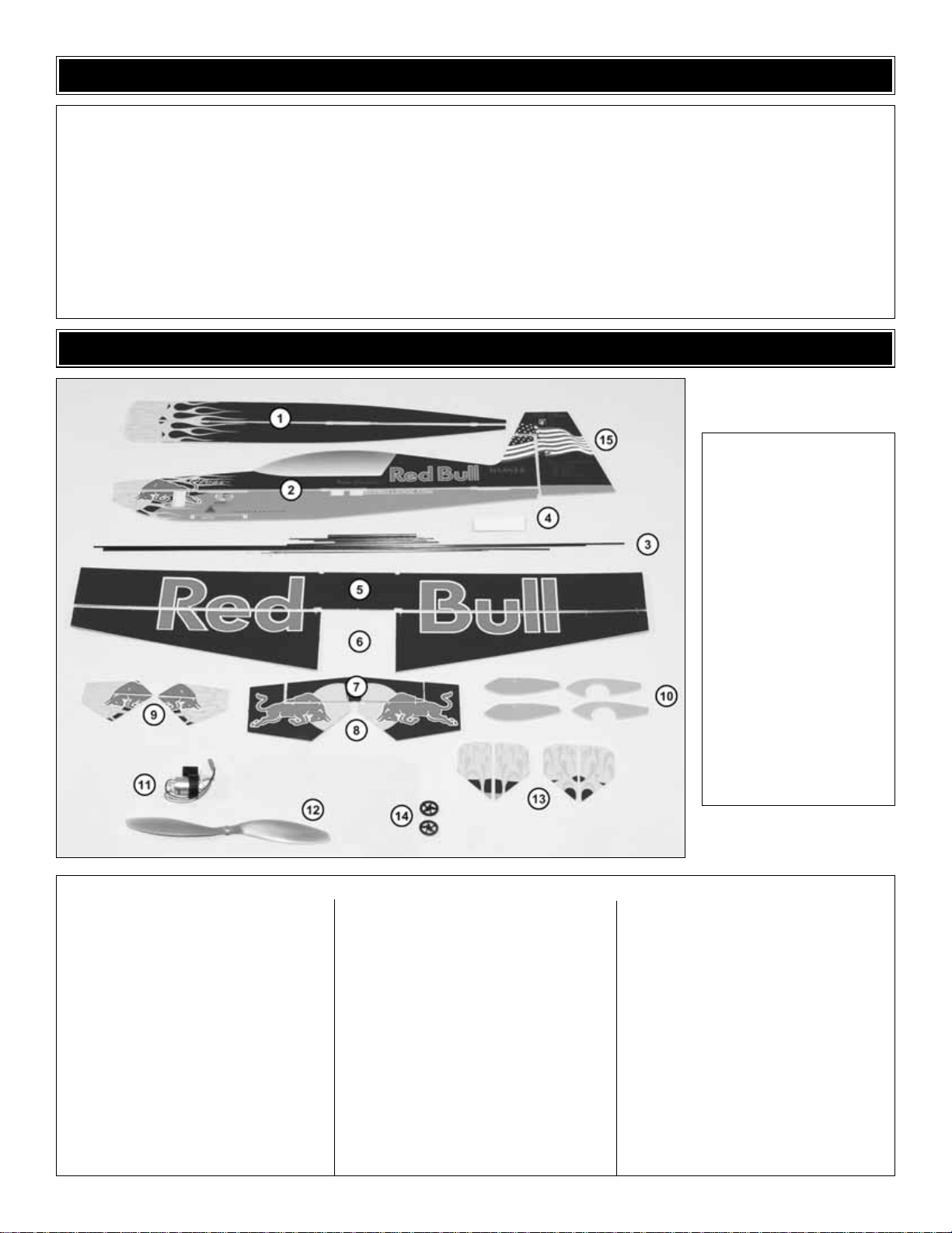
Kit Contents
1. Horizontal Fuselage
Halves (2)
2. Vertical Fuselage
Halves (2)
3. Carbon Rods & Tubes
4. Hook & Loop Fastener
5. Wing
6. Ailerons (2)
7. Horizontal Stabilizer
8. Elevator Halves (2)
9. Vertical Fuselage
Doublers (2)
10. Wheel Pants
11. Motor/Gearbox
12. Propeller
13. Horizontal Fuse
Doublers (2)
14 Main Wheels (2)
15 Rudder
Page 6
6
ORDERING REPLACEMENT PARTS
Replacement parts for the Great Planes FlatOuts Edge 540 ARF are available using the order numbers in the Replacement
Parts List that follows.The fastest, most economical service can be provided by your hobby dealer or mail-order company.
To locate a hobby dealer, visit the Hobbico web site at
www.hobbico.com
.Choose “Where to Buy”at the bottom of the menu
on the left side of the page.Follow the instructions provided on the page to locate a U.S., Canadian or International dealer.
If a hobby shop is not available, replacement parts may also be ordered from Tower Hobbies at
www.towerhobbies.com
,
or by calling toll free (800) 637-6050.
Parts may also be ordered directly from Hobby Services by calling (217) 398-0007, or via facsimile at (217) 398-7721, but
full retail prices and shipping and handling charges will apply. Illinois and Nevada residents will also be charged sales tax.
If ordering via fax, include a Visa
®
or MasterCard®number and expiration date for payment.
Mail parts orders and payments by personal check to:
Hobby Services
3002 N. Apollo Drive, Suite 1
Champaign, IL 61822
Be certain to specify the order number exactly as listed in the Replacement Parts List. Payment by credit card or personal
check only; no C.O.D.
If additional assistance is required for any reason contact Product Support by e-mail at
, or
by telephone at (217) 398-8970.
Replacement Parts List
Or
der Number
Description How to Pur
chase
Missing pieces....................................................Contact Product Support
Instruction manual ..............................................Contact Product Support
Full-size plans .....................................................Not available
Kit parts listed below ..........................................Hobby Supplier
GPMP0217 .............Gear Drive Body
GPMG0860.............Prop Shaft & Spur Gear
GPMG0239.............Pinion Gear
GPMG0312.............Replacement Motor
APCQ5016..............10 x 3.8
" Propeller
GPMQ4620.............Prop Saver
GPMA2794 .............Hardware Set
GPMG0215.............Motor/Gear Drive Assembly
GPMQ4618.............Prop Saver O-Ring
To convert inches to millimeters, multiply inches by 25.4
Page 7
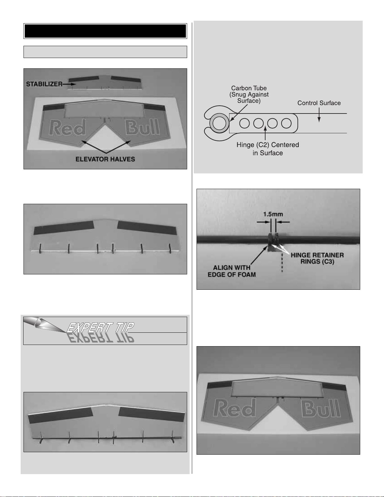
❏ 1. Cut the stabilizer free from the foam sheet using a
hobby knife with a
sharp
#11 blade.
DO NOT
cut the
elevator halves free at this time.
❏ 2. Following the
Expert Tip
below, use foam-safe CA and
accelerator to glue six clip hinges (C2) into the stabilizer, using
the 3 x 208mm [1/8" x 8-1/4"] elevator joiner tube as a guide.
Remove the elevator joiner tube from the hinges.
HOW TO INSTALL CLIP HINGES
The clip hinge system provides a precise, free-moving hinge.
Always use this method when instructed to install clip hinges.
A. Snap all of the hinges onto the carbon tube. Align the
hinges with the slots.
B. Coat both sides of one hinge (C2) with foam-safe CA
where it contacts the sides of the hinge slot. Rotate the
hinge down into the slot. Be certain the top and bottom of
the hinge remain flush with the top and bottom of the control
surface you are hinging.IMPORTANT: Avoid getting an y CA
on the tube or the arms of the clips. The clips must rotate
freely on the tube.
C. One at a time, coat the sides of the rest of the hinges and
glue them into the slots.
❏ 3. Without removing the elevator halves from the foam
sheet, slide two hinge retainer rings (C3) onto the elevator
joiner tube.Align the rings with the cutout in the right elevator
half.There should be a 1.5mm [1/16"] gap between the two
rings.Secure both rings to the tube with a drop of glue on the
outside of the gap.Do not get any glue between the rings.
❏ 4.Using the
Expert Tip
that follows, permanently join the
elevator halves by gluing in the elevator joiner tube.
Assemble the Horizontal Tail
BUILD THE AIRPLANE
7
Page 8
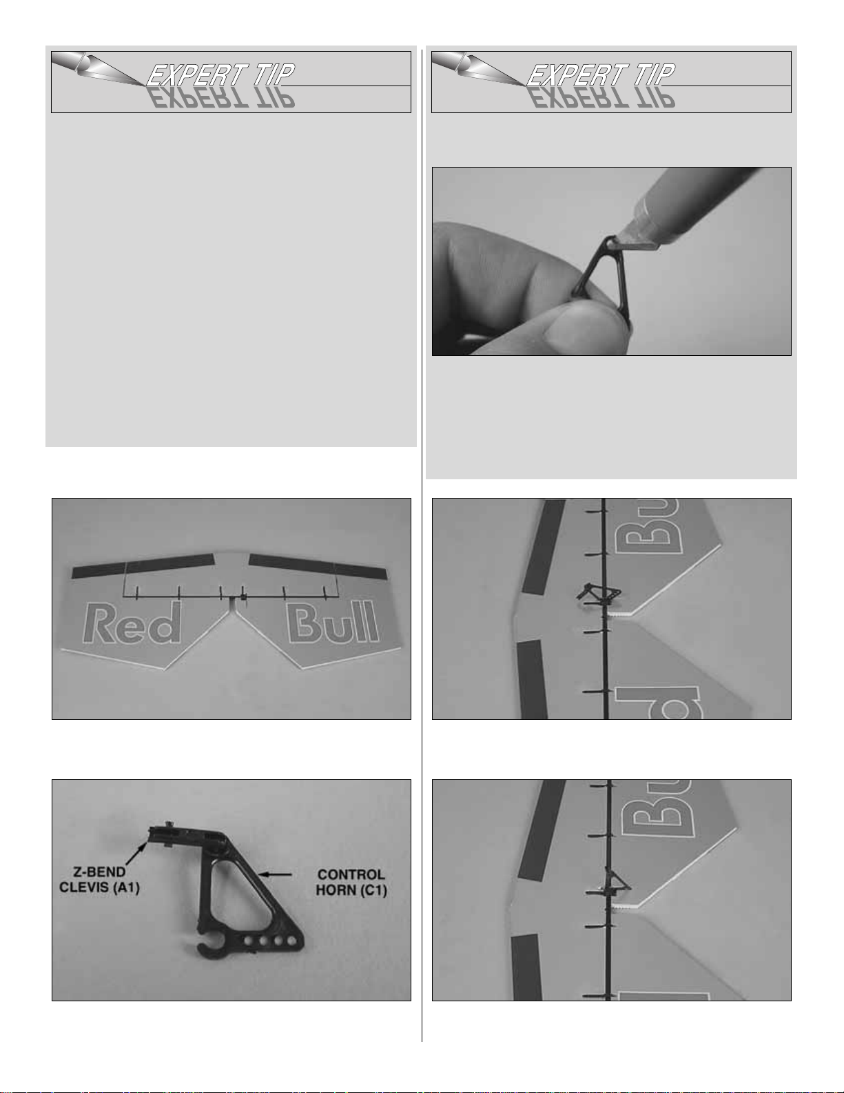
HOW T O GLUE THE TUBES TO
THE CONTROL SURFACES
Note: You may want to protect your work surface from
excess glue. We recommend Great Planes Plan Protector
(GPMR6167) for this purpose.
A. Cut several 1-1/2" [38mm] pieces of cellophane tape. Fold
the last 1/4" [6mm] over to make a tab for easy removal.
B. Lightly coat the leading edges of the elevators with f oam-saf e
CA–do not use an excessive amount.Hint: A CA applicator tip
is recommended to accurately control the bead of glue.
C. Tape the tube to the leading edge of the elevators.Weigh
the assembly down on a flat surface to prevent warping and
allow the glue to harden without accelerator.
D. Once the glue has hardened, remove the tape.
❏ 5. Now the elevator halves may be cut from the sheet.
❏ 6. Join the elevators to the stab by snapping the clip
hinges to the joiner tube.
❏ 7. Inser t a Z-bend clevis (A1) into a clip hinge control
horn (C1).
HOW TO INSTALL Z-BEND CLEVISES MORE EASILY
A. Using a sharp #11 hobby knife, remov e any flashing from the
inside of the hole you are installing the Z-bend clevis into .Do this
by rotating the blade in the hole while applying gentle pressure.
Be careful not to remove too much material–your goal here is to
remove small ridges of flashing, not to make the hole larger.
B. Snap the Z-bend clevis into place.
❏ 8. Clip the control horn onto the joiner tube aligned with
the precut slot.
❏ 9. Coat the gluing area on the control horn with glue and
rotate it down into the precut slot.
8
Page 9
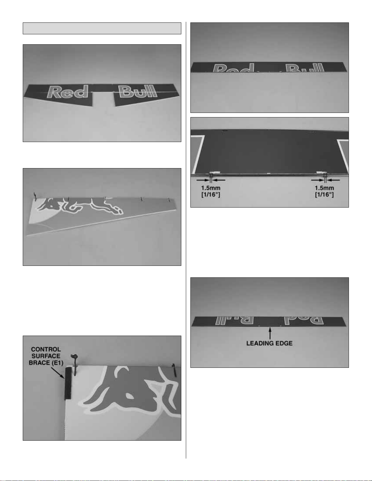
❏ 1. Cut the wing and ailerons from the foam sheet.
❏ 2. Insert offset Z-bend clevises (A2) into opposing sides
of two clip hinge control horns. Following the
Expert Tip
previously described, use the 3 x 900mm [1/8" x 35-1/2"] wing
trailing edge tube as a guide to glue four hinges and a control
horn into each aileron.The control horns should protrude from
the bottom of the ailerons, and the offset Z-bend clevises
should be on the inboard sides of the horns.Remove the tube
once the CA has hardened.
❏ 3. Glue a control surface brace (E1) onto the roots of
the ailerons.
❏ 4. Slide four hinge retainer rings (C3) onto the wing
trailing edge tube. Position the rings so that they align with
the outer slots in the TE of the wing. Secure each retainer
with a drop of glue on the outside of the gap. Glue the
trailing edge tube to the TE of the wing.Be careful not to get
glue between the rings.
❏ 5. Glue the 3 x 900mm [1/8" x 35-1/2"] wing leading
edge tube to the LE of the wing.
Assemble the Wing
9
Page 10
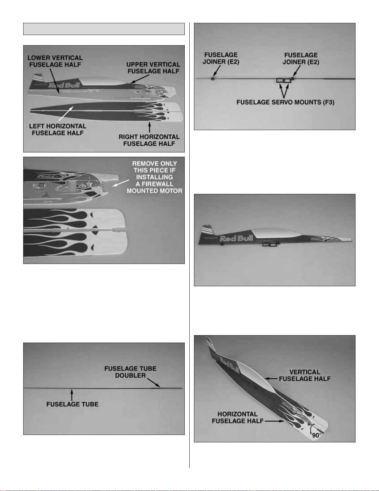
❏ 1.Cut the upper and lower vertical fuselage halves and
the right and left horizontal fuselage halves free from their
foam sheets. If using the gearbox included with this kit, or
any other type of “stick-mount” gearbox, cut out all four
sections from the fuselage parts. If using a firewall-mounted,
brushless outrunner motor, cut out only the section from the
lower vertical fuselage.
❏ 2. Glue the 5.5 x 154mm [7/32" x 6"] fuselage tube
doubler ov er the 3 x 715mm [1/8" x 28-1/8"] fuselage tube.
One end should be flush. From now on, this assembly will
be referred to as the fuselage tube.
❏ 3. Slide a fuselage joiner (E2), two fuselage servo
mounts (F3), and another fuselage joiner onto the fuselage
tube. With the tube doubler forward, and the servo mounts
hanging down, the front servo mount should have its flat
surface on the left, and the rear servo mount should hav e its
flat surface on the right.
❏ 4.Position the servo mounts and fuselage joiners so that they
align with the precut slots in the upper vertical fuselage half.
❏ 5. Glue the fuselage tube to the upper vertical fuselage half.
❏ 6.Glue the left and right horizontal fuselage halves to the
fuselage tube. Make sure they are perpendicular to the
upper vertical fuselage.
Assemble the Fuselage
10
Page 11
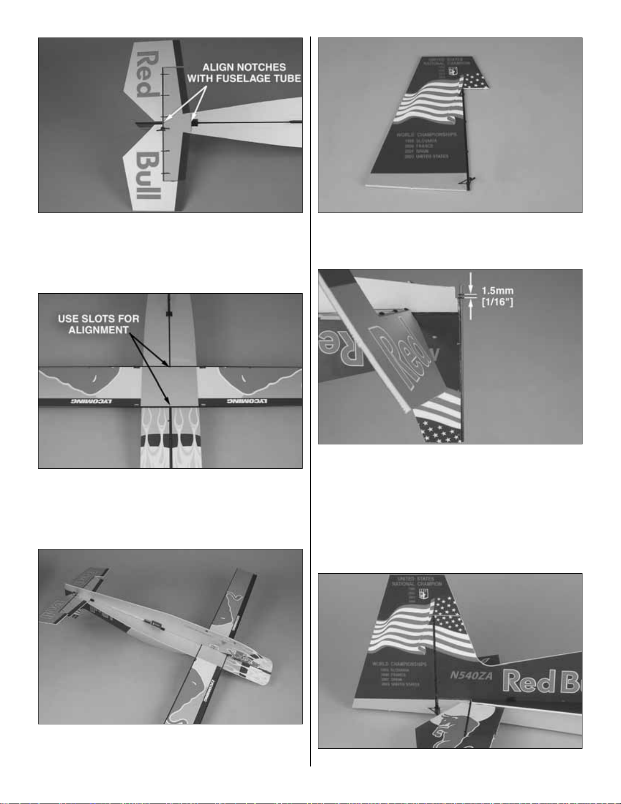
❏ 7. Glue the stabilizer into position with the leading edge
of the stab butted against the rear fuselage joiner. Align the
notches in the stab with the fuselage tube.
❏ 8.Glue the wing into position with the leading edge of the
wing against the rear end of fuselage doubler tube.Align the
notches in the wing with the fuselage tube.
❏ 9. Glue the lower vertical fuselage half to the fuselage
tube. Make sure to keep it parallel with the upper half and
perpendicular to the horizontal fuselage.
❏ 10.Using the 3 x 154mm [1/8" x 6"] rudder post tube as
a guide, glue three clip hinges and a clip hinge control horn
to the rudder.
❏ 11. Remove the rudder post tube from the rudder. Slide
two hinge retainer rings onto the bottom of the rudder post.
Align the rings with the slot in the TE of the fuselage.Secure
each ring with a drop of glue on the outside. Be careful not
to get glue between the rings.
❏ 12.Glue the rudder post tube to the TE of the v ertical fuse.
❏ 13. Snap the rudder onto the r udder post.
11
Page 12
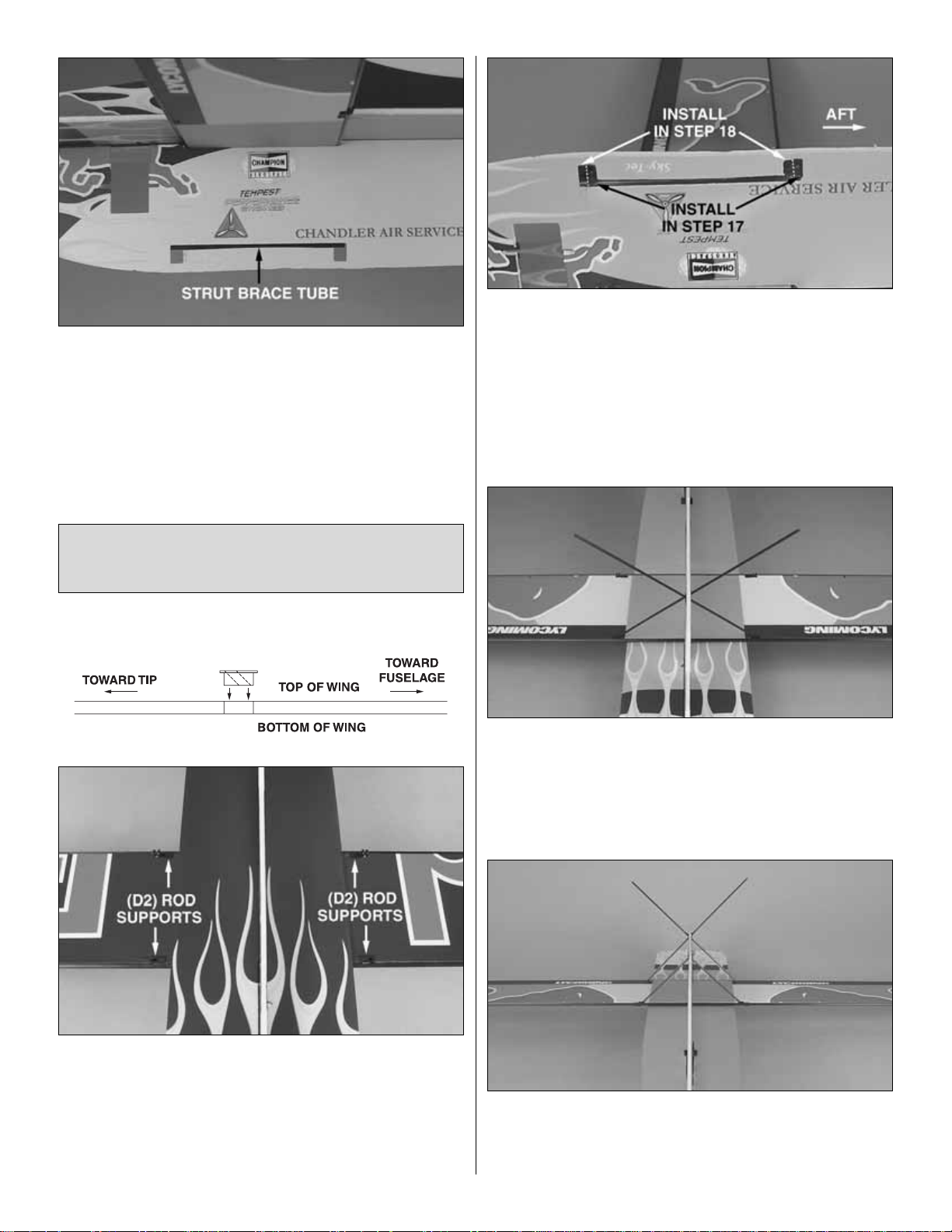
❏ 14. Glue the 3 x 90mm [1/8" x 3-1/2"] strut brace tube
into the fuselage.
❏ 15. Locate eight rod supports (D2). In the following
steps note that four of the supports will be used for the main
landing gear and four of the supports will be used for the
wing struts at the trailing edge of the wing, but all of the
supports are exactly the same.
❏ 16.Installing them down through the top of the wing, glue
four rod supports (D2) into the slots in both sides of the
wing. Two of the supports are at the leading edge (for the
landing gear) and two are at the trailing edge (for the wing
struts). IMPORTANT: The holes in the supports must be
angled upward and outward (matching the angle of the
landing gear and the wing struts).
❏ 17. Installing them from the right side, glue two more
supports into the slots in the fuselage. Note that these first
two supports should be positioned aft in the slots, and that
the holes in the supports should be angled downward and
outward (again, to accommodate the angles of the landing
gear and the struts).
❏ 18. Glue the remaining two supports into the left side of
the fuselage. Be certain that the holes are angled correctly.
❏ 19.Slide the 2 x 195mm [5/64" x 7-5/8"] landing gear legs
through the landing gear supports in the front of the wing and
fuselage. Ensure that the wing is parallel with the stab and
horizontal fuselage and perpendicular to the vertical fuselage.
Once satisfied with the alignment, secure the landing gear
legs with a drop of glue on both sides of each joint.
❏ 20.Slide the 2 x 94mm [5/64" x 3-5/8"] wing struts through
both sets of supports in the back of the wing and fuselage.
Make sure that the TE of the wing is aligned with the LE, and
secure the struts with a drop of glue on both sides of each joint.
IMPORTANT!!! Before gluing in any of the supports, be
certain to read the steps all the way through so you will
understand how the supports go in.
12
Page 13
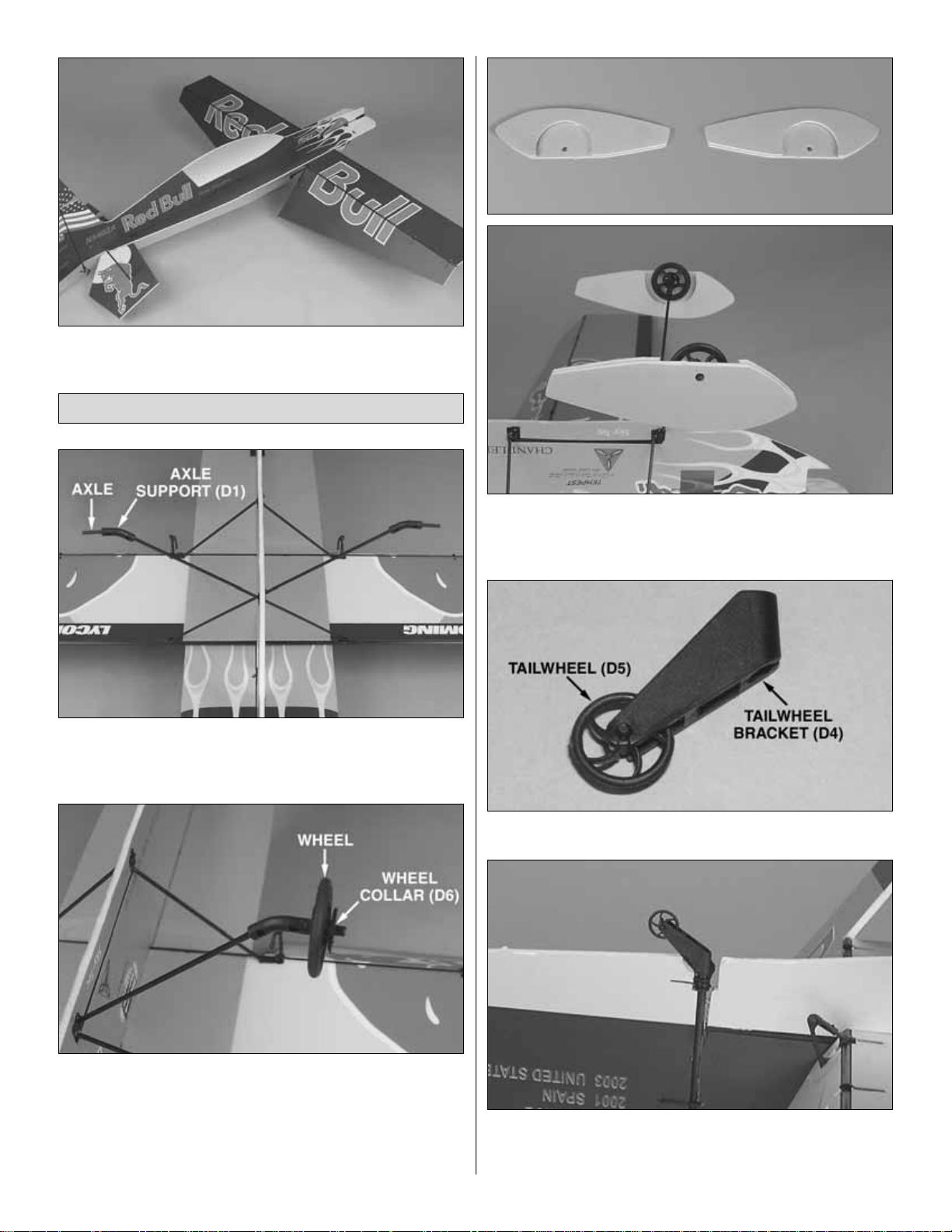
❏ 21. Snap the ailerons onto the wing TE.
❏ 1. Install a 2 x 17mm [5/64" x 21/32"] axle and axle
support (D1) onto each landing gear leg. Make sure that
the axles are perpendicular to the centerline.
❏ 2. Slide the wheels onto the axles and secure them with a
wheel collar (D6).The flat side of the wheel collar should be
toward the wheel.Secure the wheel collar with a drop of glue
in the
teeth
opposite the wheels. Align the wheels with the
centerline and secure the axles and supports with a drop of
glue through the holes in both sides of the axle supports.
❏ 3. Make two wheel pants by gluing the inner and outer
wheel pant parts together. Be sure to make a right and a
left.Glue the inside of both wheel pants to the wheel collars.
❏ 4. Snap the tailwheel (D5) into the tailwheel bracket (D4).
❏ 5. Slide the tailwheel bracket over the rudder and rudder
post. Glue the bracket to the rudder
only.Do not
glue the
bracket to the rudder post.
Finish the Landing Gear
13
Page 14
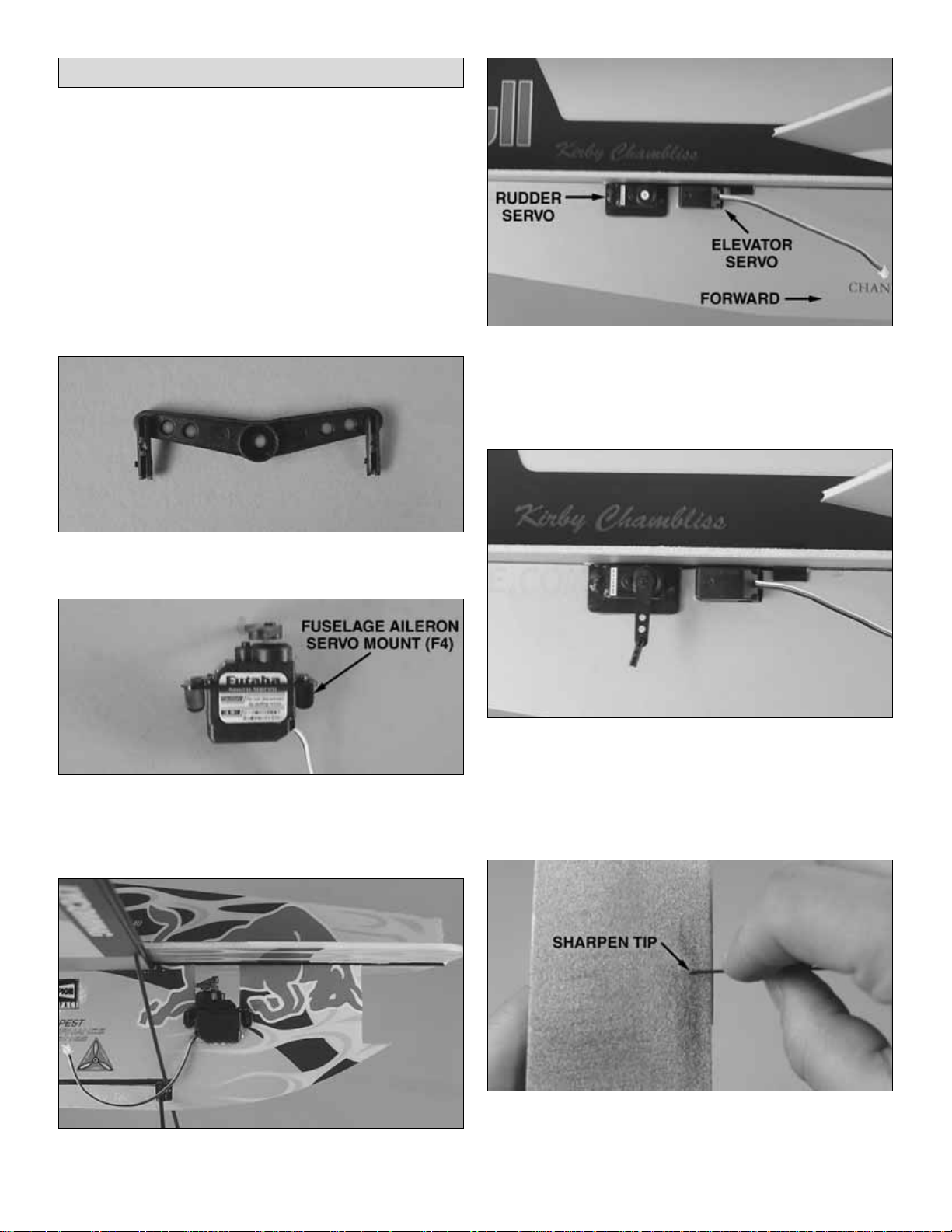
❏ 1.Remove the stock servo arms from all three of the servos
and temporarily connect the servos and ESC to your receiver.
Power up the system and center all three servos.
❏ 2.Refer to the “
Plastic T ree Parts”
listing on page 5 and
select the correct offset double-sided servo arm for the
aileron servo you will be using. There are three arms to
choose from:
Servo Arm A: Hitec HS-55, Hitec HS-50, Futaba 3108M
Servo Arm B: Futaba S3103, Airtronics 94091
Servo Arm C: JR 241
❏ 3. Install two Z-bend clevises into the
underside
of the
offset double-sided servo arm.
❏ 4. Install the servo arm on the aileron servo in the
position shown. Both ar ms should be offset forward by the
same angle. Glue the aileron ser vo into a fuselage aileron
servo mount (F4).
❏ 5.With the output shaft aft, glue the aileron servo into the
cutout under the wing.
❏ 6.Glue the rudder servo into the rear servo mount in the
left side of the fuselage.The output shaft should be forward.
❏ 7.Glue the elevator servo into the front servo mount in the
right side of the fuselage.The output shaft should be forward.
❏ 8. Select two single-sided ser vo arms to fit the elevator
and rudder servos you are using. Insert a Z-bend clevis into
the outer hole of each arm. Mount the servo arms so that
they point straight down with the servos centered. Cut a
small hole in the fuselage to allow the elev ator servo wire to
pass through to the right side of the fuselage.
❏ 9. Using an Easy-Touch
™
bar sander with 220-grit
sandpaper, sharpen the ends of all the 1mm [3/64"] carbon
pushrods. This will make it much easier to install them
through the Z-bend clevises.
Radio Setup
14
Page 15
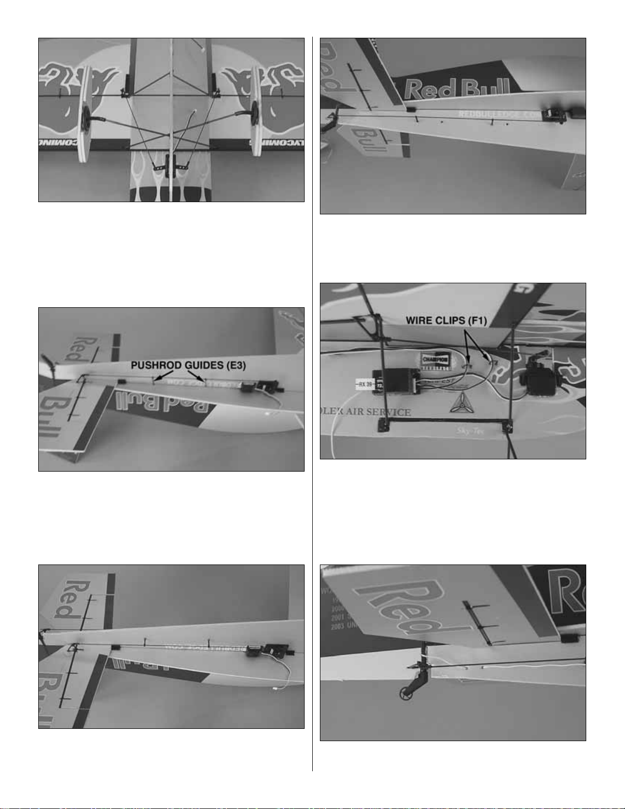
❏ 10. Slide a 1 x 117mm [3/64" x 4-5/8"] aileron pushrod
through the clevises in the aileron horns and servo arms.
Adjust the clevises until the ailerons are centered with the
servo centered. When you have the alignment correct,
secure the pushrod with a drop of glue where the pushrod
enters the clevis.Keep glue away from the end of the clevis
where it pivots in the arm or horn.
❏ 11. Slide two pushrod guides (E3) onto the 1 x 300mm
[3/64" x 11-7/8"] elevator pushrod and slide the pushrod
through the clevises on the elevator servo arm and control
horn. Adjust the clevises until the elevator is centered with
the servo centered. Secure the clevises with a drop of glue
on each clevis where the pushrod enters it.
❏ 12.Using the pushrod as a guide, drill two evenly spaced,
2.4mm [3/32"] holes through the fuselage for the pushrod
guides. Glue the base of each pushrod guide into the holes.
❏ 13.Install the 1 x 315mm [3/64" x 12-3/8"] rudder pushrod
the same way.
❏ 14. Connect all three servos to the receiver. Mount the
receiver to the bottom of the left horizontal fuselage with
double-sided foam tape.Make sure the receiver is far enough
forward so that it does not interf ere with aileron motion.Secure
any excess wire with wire clips (F1).
❏ 15.Drill two 1.5mm [1/16"] holes through the fuselage where
shown.“Stitch” the receiver antenna through these holes.
15
Page 16
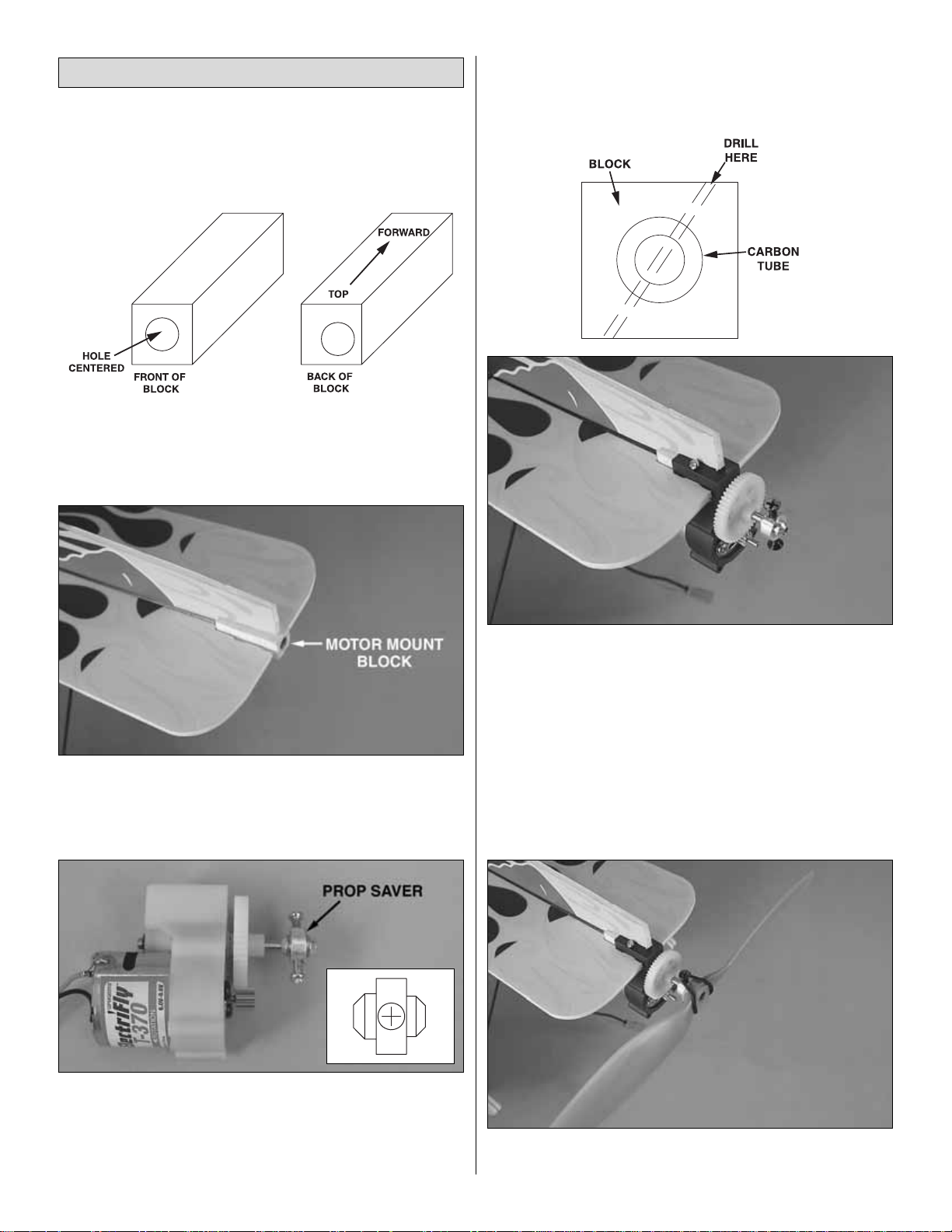
If mounting the included stick-mounted motor and gearbox or an
after-market geared brushless system, follow the instructions in
this section. If mounting a firewall-mounted motor system,
proceed to
“Firewall-Mounted Motor System”
on page 17.
❏ 1. The 10 x 10 x 27mm [25/64" x 25/64" x 1-1/16"]
hardwood motor mount block must be mounted in the
correct orientation. Identify the top, aft end of the block as
shown in the sketch so you will know how it is installed.
❏ 2. Without using any glue, slide the motor mount block
over the fuselage tube.Be certain the block is in the correct
position so there will be down and right thrust. Do not glue
the motor mount block onto the fuselage tube.
❏ 3. If using the included propeller, install the prop saver
onto the gearbox shaft with the large-diameter cone
forward.If using a GWS prop, install the prop saver with the
small-diameter cone forward. Tighten the screws, making
sure they engage the flat spots on the shaft.
❏ 4. Slide the motor/gearbox assembly over the motor
mount block.
❏ 5.Drill a 1.5mm [1/16"] pilot hole at an angle from the top of
the gearbox through the balsa block and carbon tubes. Make
sure the motor mount block does not rotate while drilling.
Secure the gearbox and block with a 2 x 8mm [5/64" x 5/16"]
wood screw.
❏ 6. If using the included APC prop, inser t the larger of the
two adapter rings (included in the propeller packaging) into
the rear of the propeller hub.
❏ 7. Secure the prop to the prop saver with one of the
included O-rings.
Mount the Motor & Gearbox
16
GPM
APC
GWS
Page 17
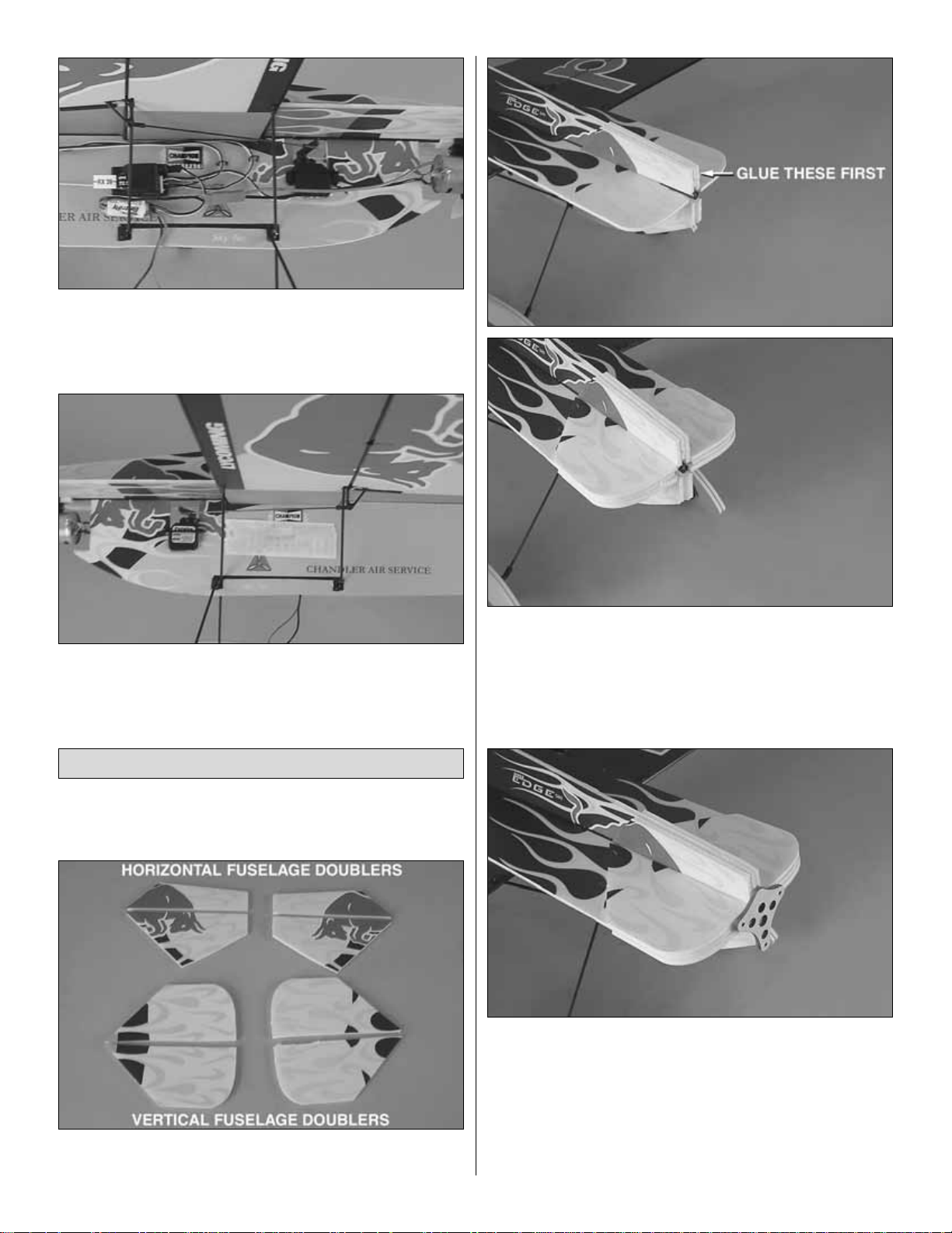
❏ 8. Connect your speed control to the motor and receiver.
Mount the speed control to the bottom of the right horizontal
fuselage with double-sided foam tape.Cut a small hole for the
ESC’s battery wire to cross to the right side of the fuselage.
❏ 9. Install the “hook” side of the included hook-and-loop
material to the left side of the fuselage where shown.This is
where you will mount the battery.
Use the following instructions if you are installing a fire wallmounted motor system (usually brushless motors).
❏ 1. Cut the horizontal and ver tical fuselage doublers
from their foam sheets.
❏ 2. Glue the ver tical fuselage doublers into position first,
then glue the horizontal fuselage doublers into position.
❏ 3. Use a 220-grit bar sander to lightly sand the front of
the fuselage even. Be careful not to change the built-in
thrust angles.
❏ 4. If installing an ElectriFly RimFire motor, glue the
included 3mm [1/8"] plyw ood firewallto the nose so that the
two pilot holes are centered on the horizontal fuselage, and
the top hole is centered on the fuselage tube. Note: If
installing another brand of outrunner motor, you will need to
cut your own firewall to match its mount pattern. The motor
and firewall should be mounted so that the thrust line is
offset 9mm [11/32"] below the center of the fuselage tube.
Firewall-Mounted Motor System
17
Page 18
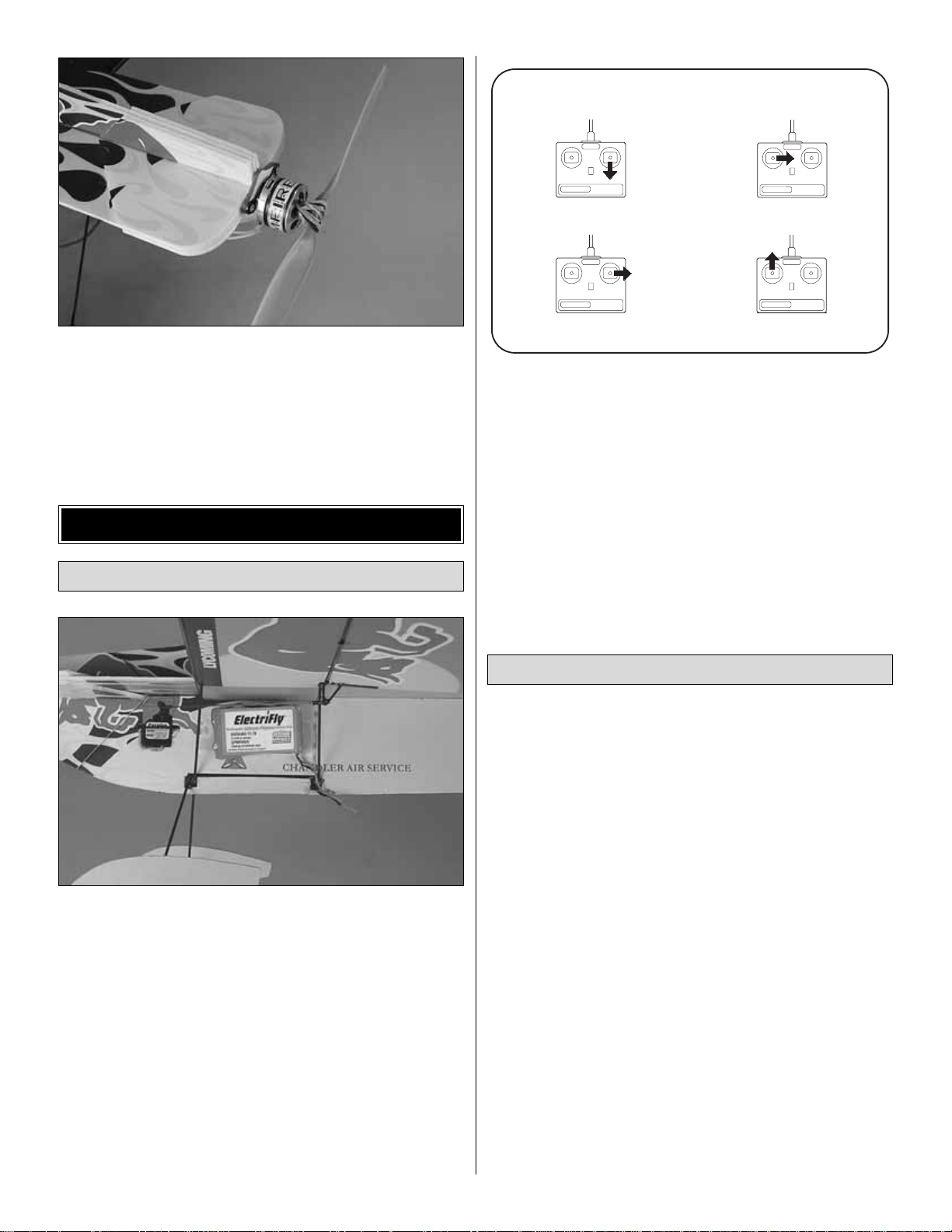
❏ 5.Mount the motor and propeller using the hardware and
instructions that came with your motor.
❏ 6. Install your ESC as instructed in step 8 of the
“Mount
the Motor & Gearbox”
section on page 16.
❏ 1. Attach the “loop” side of the hook-and-loop material to
the battery. Mount the battery to the fuselage.
❏ 2. For safety, remove the propeller while performing
bench set-up. Once you have finished setting up your
airplane, you can reinstall it.
❏ 3. Lower the throttle stick all the way and turn on the
transmitter.Connect your battery to the ESC. If the ESC has
a BEC switch, turn it on.
❏ 4. Check all the control surfaces to see if they are
centered. Since you set the center points as you set up the
linkages, they should already be very close. Use the trims
on the transmitter to center the controls.
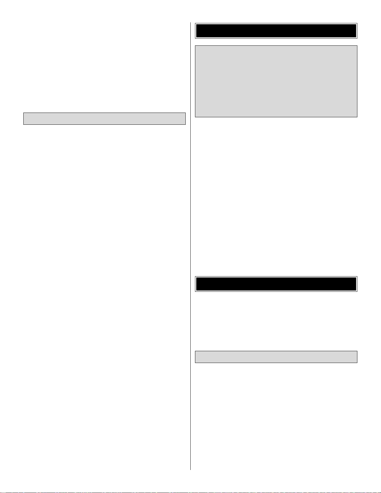
❏ 5. Make cer tain that the control surfaces and the motor
respond in the correct direction as shown in the diagram.To
operate the motor, you may have to “arm” your ESC.Follow
the instructions that came with your ESC to do this.If any of
the controls respond in the wrong direction, use the servo
reversing in the transmitter to reverse the servos connected
to those controls. Be certain the control surfaces have
remained centered. Adjust if necessary.
To simplify setup, the high-rate (3D) control throws for this
model are automatically set by the geometry of the included
hardware. We do recommend, however, that you perform a
quick check as described below to make sure the thro ws are
set up correctly.
Note: If your radio has the capability, low rates will make it
easier to perform precision aerobatics. We recommend 40%
endpoints for all low rate throws. If your radio does not have
low rates, set up the plane using only the high rate throws.
Additionally, you ma y w ant to use the e xponential function to
soften the control response around center.This is largely a
matter of personal taste, but helps many pilots balance the
extreme throws needed for 3D flying with the need to make
small corrections when in normal flight.
We recommend setting up your airplane according to the
table shown below
as a starting point
. However, setting up
models of this type is largely a matter of personal taste.We
encourage you to tune the throws to your taste as you get
more familiar with the aircraft.Many expert 3D fliers choose
to increase their high rate travel by using higher endpoints.
Set the Control Throws
4-CHANNEL RADIO SETUP
Check the Control Directions
GET THE MODEL READY TO FLY
18
(STANDARD MODE 2)
4-CHANNEL
TRANSMITTER
ELEVATOR MOVES UP
4-CHANNEL
TRANSMITTER
RIGHT AILERON MOVES UP
LEFT AILERON MOVES DOWN
RUDDER MOVES RIGHT
FULL THROTTLE
4-CHANNEL
TRANSMITTER
4-CHANNEL
TRANSMITTER
Page 19
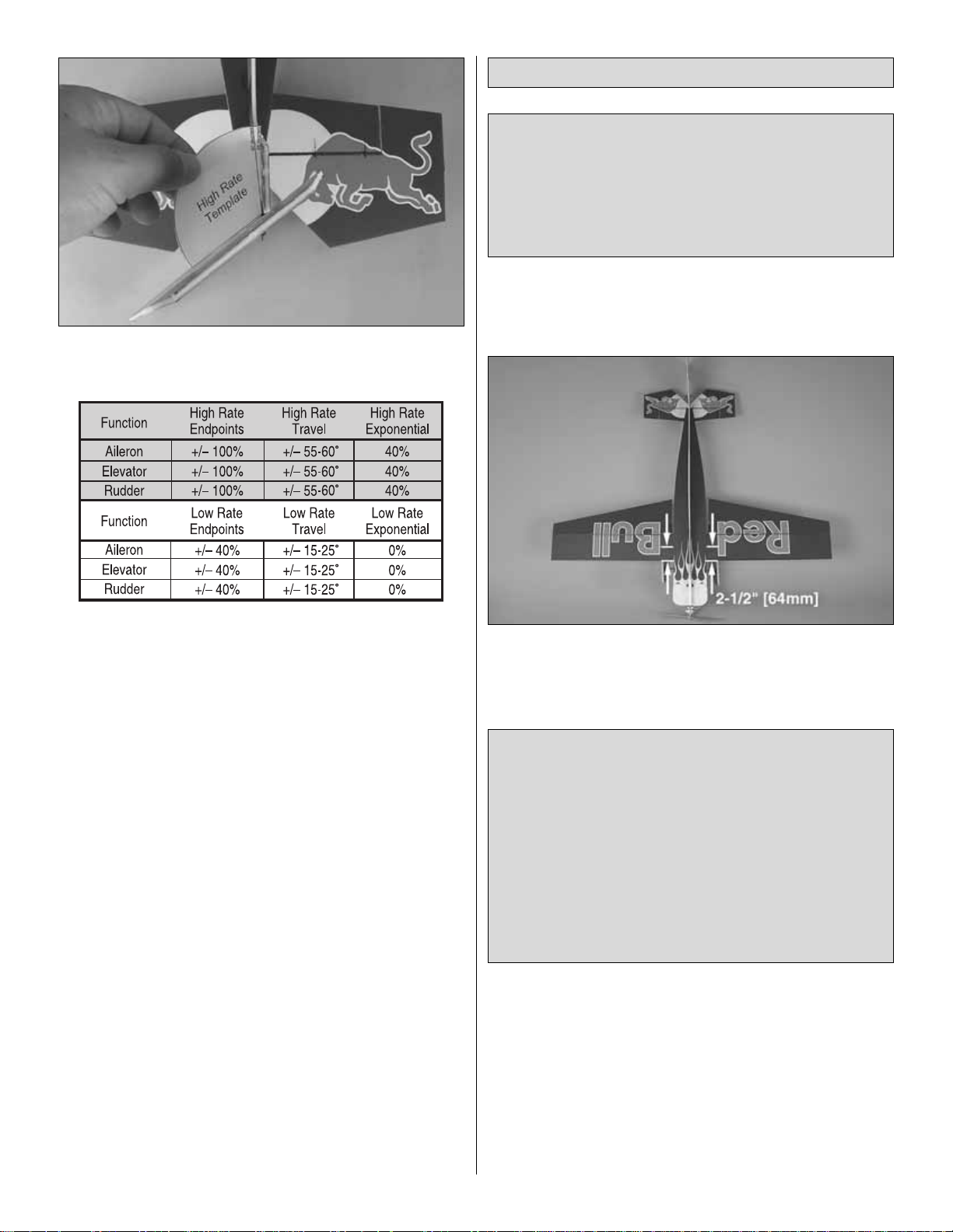
To set the throws, use the Angle Templates on the back cover
page of this manual to verify that you are in the ballpark.
If you are not able to achieve these control throws, doublecheck your pushrod hookup and make sure any control
surfaces in question are operating smoothly. If you have a
computer radio, also make sure your endpoint adjustments
are properly set.
At this stage the model should be in ready-to-fly condition
with all of the systems in place including the motor, the
propeller, the battery, and the radio system.
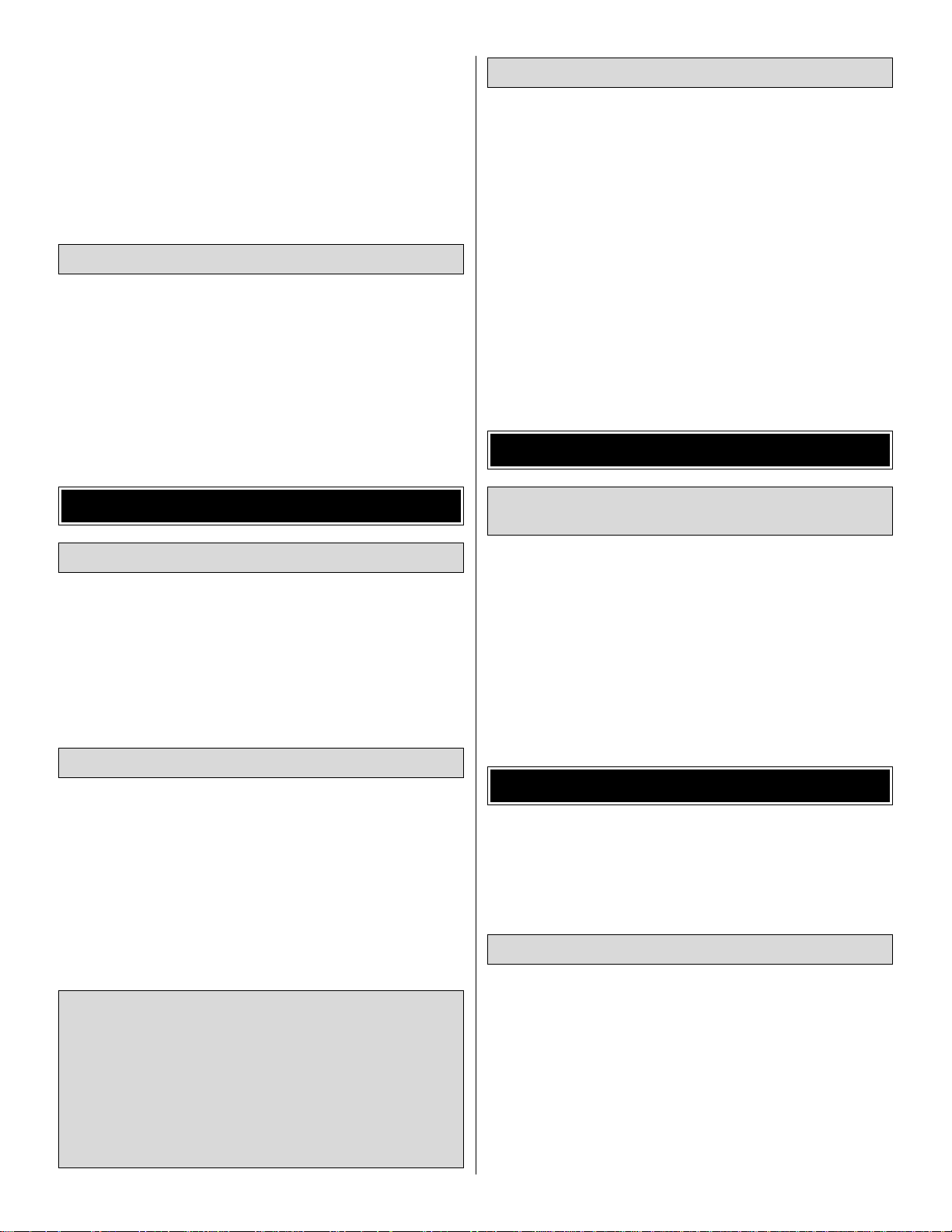
❏ 1.Use a felt-tip pen or 1/8" [3mm]-wide tape to accurately
mark the C.G. on the top of the wing on both sides of the
fuselage. The C.G. is located 2-1/2" [64mm] back from the
leading edge of the wing at the fuselage.
❏ 2. With all parts of the model installed, including the
battery (ready to fly), lift it upside-down on your fingertips at
the balance point you marked.
❏ 3. If the tail drops, the model is “tail heavy” and the battery
pack and/or receiver must be shifted forward or weight must
be added to the nose to balance.If the nose drops, the model
is “nose heavy”and the battery pack and/or receiver must be
shifted aft or weight must be added to the tail to balance. If
possible, relocate the battery pack on the hook-and-loop strip
This is where your model should balance for the first
flights. Later, you may wish to experiment by shifting the
C.G. up to 1/2" [13mm] forward or 1/2" [13mm] back to
change the flying characteristics. Moving the C.G. forward
may improve the smoothness and stability, but the model
may then require more speed for tak eoff and mak e it more
difficult to slow for landing or 3D aerobatics. Moving the
C.G. aft makes the model more maneuverable, but could
also cause it to become too difficult to control.In any case,
start at the recommended balance point. As with the
throws, though, we encourage you to experiment with the
CG until the model flies to your taste.
More than any other factor, the C.G. (balance point) can
have the greatest effect on how a model flies, and may
determine whether or not your first flight will be successful.
If you value this model and wish to enjoy it for many flights,
DO NOT OVERLOOK THIS IMPORTANT PROCEDURE.
A model that is not properly balanced will be unstable and
possibly unflyable.
Balance the Model (C.G.)
19
Page 20
to minimize or eliminate any additional ballast required. If
additional weight is required, begin by placing incrementally
increasing amounts of weight on the bottom of the fuse until
the model balances. Once you have determined the amount
of weight required, it can be permanently attached.
❏ 4. IMPORTANT: If you found it necessary to add any
weight, recheck the C.G.after the weight has been installed.
❏ 1. With the wing level, lift the model by the engine
propeller shaft and the bottom of the fuse under the TE of
the fin. Do this several times.
❏ 2.If one wing always drops when you lift the model, it means
that side is heavy. Balance the airplane by adding weight to the
other wing tip.An airplane that has been laterally balanced
will track better in loops and other maneuvers.
No matter if you fly at an AMA sanctioned R/C club site or if
you fly somewhere on your own, you should always have
your name, address, telephone number and AMA number
on your model.It is required at all AMA R/C club flying sites
and AMA sanctioned flying events.Write this information on
the bottom of the wing with a fine felt-tip pen.
Follow the battery charging instructions that came with your
radio control system to charge the batteries.You should always
charge your transmitter batteries the night before you go flying,
and at other times as recommended by the radio manuf acturer .
Charge the flight battery using a charger designed for
Lithium-Polymer batteries. Charging with any other type of
charger is very dangerous, and may cause the batteries to
combust violently.
Ground check the operational range of your radio before the
first flight of the day. With the transmitter antenna collapsed
and the receiver and transmitter on, you should be ab le to walk
at least 15m [50 feet] away from the model and still have
control. Have an assistant stand by your model and, while you
work the controls, tell you what the control surfaces are doing.
Repeat this test with the motor running at various speeds
with an assistant holding the model, using hand signals to
show you what is happening. If the control surfaces do not
respond correctly, do not fly! Find and correct the problem
first. Look for loose servo connections or broken wires,
corroded wires on old servo connectors, poor solder joints in
your battery pack or a defective cell, or a damaged receiver
crystal from a previous crash.
Keep your f ace and body as w ell as all spectators a wa y from
the plane of rotation of the propeller whenever the battery
is connected.
Keep these items away from the prop: loose clothing, shir t
sleeves, ties, scarfs, long hair or loose objects such as
pencils or screwdrivers that may fall out of shirt or jacket
pockets into the prop.
Read and abide by the following excerpts from the Academy
of Model Aeronautics Safety Code.For the complete Safety
Code refer to
Model Aviation
magazine, the AMA web site or
the Code that came with your AMA license.
1) I will not fly my model aircraft in sanctioned ev ents, air shows,
or model flying demonstrations until it has been proven to be
airworthy by having been previously, successfully flight tested.
2) I will not fly my model aircraft higher than approximately
122m [400 feet] within 5km [3 miles] of an airport without
notifying the airpor t operator. I will give right-of-way and avoid
flying in the proximity of full-scale aircraft.Where necessary , an
observer shall be utilized to supervise flying to avoid having
models fly in the proximity of full-scale aircraft.
General
AMA SAFETY CODE (excerpts)
Failure to follow these safety precautions may result
in severe injury to yourself and others.
MOTOR SAFETY PRECAUTIONS
Range Check
CAUTION: Unless the instructions that came with your
radio system state differently, the initial charge on new
transmitter batteries should be done for 15 hours using
the slow-charger that came with the radio system.This
will “condition” the batter ies so that the next charge may
be done using the fast-charger of your choice.If the initial
charge is done with a fast-charger, the batteries may not
reach their full capacity and you may be flying with
batteries that are only partially charged.
Charge the Batteries
Identify Y our Model
PREFLIGHT
Balance the Model Laterally
20
Page 21
3) Where established, I will abide by the safety rules for the
flying site I use, and I will not willfully and deliberately fly my
models in a careless, reckless and/or dangerous manner.
5) I will not fly my model unless it is identified with my name
and address or AMA number, on or in the model.Note: This
does not apply to models while being flown indoors.
7) I will not operate models with pyrotechnics (any device
that explodes, burns, or propels a projectile of any kind).
1) I will have completed a successful radio equipment ground
check before the first flight of a new or repaired model.
2) I will not fly my model aircraft in the presence of
spectators until I become a qualified flier, unless assisted b y
an experienced helper.
3) At all flying sites a straight or curved line(s) must be
established in front of which all flying takes place with the
other side for spectators.Only personnel involv ed with flying
the aircraft are allowed at or in the front of the flight line.
Intentional flying behind the flight line is prohibited.
4) I will operate my model using only radio control frequencies
currently allowed by the Federal Communications Commission.
5) I will not knowingly operate my model within three
miles of any pre-existing flying site except in
accordance with the frequency sharing agreement
listed [in the complete AMA Safety Code].
9) Under no circumstances may a pilot or other person touch
a powered model in flight; nor should any part of the
model other than the landing gear intentionally touch
the ground, except while landing.
❏ 1. Check the C.G. according to the measurements
provided in the manual.
❏ 2. Be certain the battery and receiver are securely
mounted on the fuse.
❏ 3. Extend your receiver antenna and make sure it
cannot get tangled in the prop.
❏ 4. Balance your model
laterally
as explained in
the instructions.
❏ 5. Make sure all hinges are securely glued in place.
❏ 6. Confirm that all controls operate in the correct direction
and the throws are set up according to the manual.
❏ 7. Make sure any servo wiring does not interfere with
other systems (servo arms, pushrods, etc.).
❏ 8. Place your name, address, AMA number and
telephone number on your model.
❏ 9. If you wish to photograph your model, do so before
your first flight.
❏ 10. Range check your radio when you get to the flying site.
The FlatOuts Edge 540 ARF is a great-flying model that flies
smoothly and predictably. The FlatOuts Edge 540 ARF does
not, however, possess the self-recovery characteristics of a
primary R/C trainer and should be flown only by experienced
R/C pilots.
For the first flight, it is a good idea to have an assistant
launch the airplane for you. This allows you to keep your
hands on the controls and immediately correct any trim
problems that are present.
Have your friend hold the FlatOuts Edge 540 ARF by the
canopy.Throttle up to full power, and giv e the plane a gentle ,
underhanded toss at about a 30° angle upward. Since the
FlatOuts Edge 540 ARF has a very high thrust-to-weight
ratio, the plane will accelerate to flying speed almost
instantly. Climb to a comfortable height and throttle back to
a lower power setting. This plane flies great at about halfthrottle when in standard forward flight.
Hand Launch
FLYING
During the last few moments of preparation your mind may
be elsewhere anticipating the excitement of the first flight.
Because of this, you may be more likely to overlook certain
checks and procedures that should be performed before the
model is flown.To help avoid this, a check list is provided to
make sure these important areas are not overlooked. Many
are covered in the instruction manual, so where appropriate,
refer to the manual for complete instructions. Be sure to
check the items off as they are completed.
CHECK LIST
Radio Control
21
Page 22
Once you have the model trimmed out, the FlatOuts Edge
540 ARF is very capable of ROG (rise-off-ground) takeoffs
from a smooth surface (parking lot, runway, gym floor, etc.).
To take off, start by advancing the throttle to about two-thirds,
making sure to correct any torque reactions with rudder.The
plane will build flying speed almost instantly due to its high
thrust-to-weight ratio.Once the tail comes up, gently apply up
elevator to break ground and climb out.Full throttle takeoffs
are necessary only for extremely short runways.
When flying a 3D aerobat like the FlatOuts Edge 540 ARF,
there are several things y ou should alwa ys keep in mind.First
is throttle management–this airplane has enough power to
climb straight up at full throttle, so level flight is more
comfortably achieved at about half-throttle. Avoid extremely
high-speed flight with the FlatOuts Edge 540 ARF–it is
designed for slow 3D aerobatics, and extended full-throttle
dives can result in wing flutter.While flutter won’t destroy the
airplane, it’s best to avoid it. Second, take it easy on the
control sticks–with 3D throws, even a small stick deflection
can result in a big response, so use small inputs (unless of
course you’re performing an aggressive maneuver).
Because this model is extremely lightweight, it slows rapidly
without power , and perf orming standard gliding landings can
be difficult. Instead, land the model under power, with a
rolling 3-point landing as the goal. To achieve this, perform
your landing approach with the model in the 3-point attitude
(nose up at such an angle that all three wheels are level).
Modulate your descent with the throttle, and use a quick
“blip”of power just before touchdown to slow the descent f or
a gentle landing.
Have a ball!
But always stay in control and fly in a safe manner.
GOOD LUCK AND GREAT FLYING!
Landing
Flight
Rise-Off-Ground (ROG) Takeoffs
22
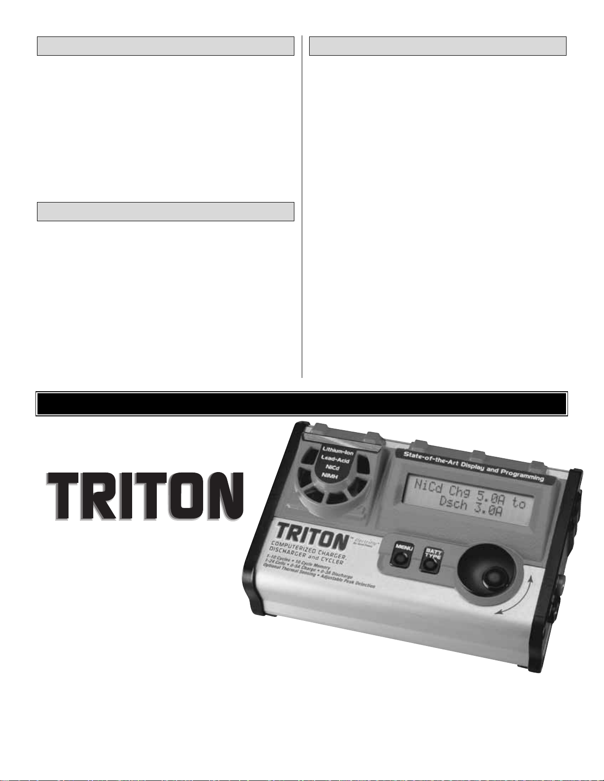
Imagine a charger so versatile it can be used with lithium-ion and lead-acid
batteries as effectively as NiCd and NiMH cells.A unit that can peak charge tiny park flyer
packs and 24V car batteries alike.A charger that can discharge as well as charge, cycle packs from
1 to 10 times automatically, memorize peak and average battery voltages for each cycle – and constantly display
battery capacity, voltage, current and time as each cycle progresses.Then, imagine that the charger, which can do all this, is
about the size of a thick paperback book, and weighs just o v er a pound.The advanced computer technology in the Triton Peak
Charger makes it possible to accomplish all this and more, through controls and menus so simple that programming is a
breeze.For more information, log on at
www.electrifly.com
– and be amazed. 1-year warranty.
GPMM3150
ALSO AVAILABLE FROM GREAT PLANES
ElectriFly T riton™Peak Charger
Page 23
23
ALSO AVAILABLE FROM GREAT PLANES
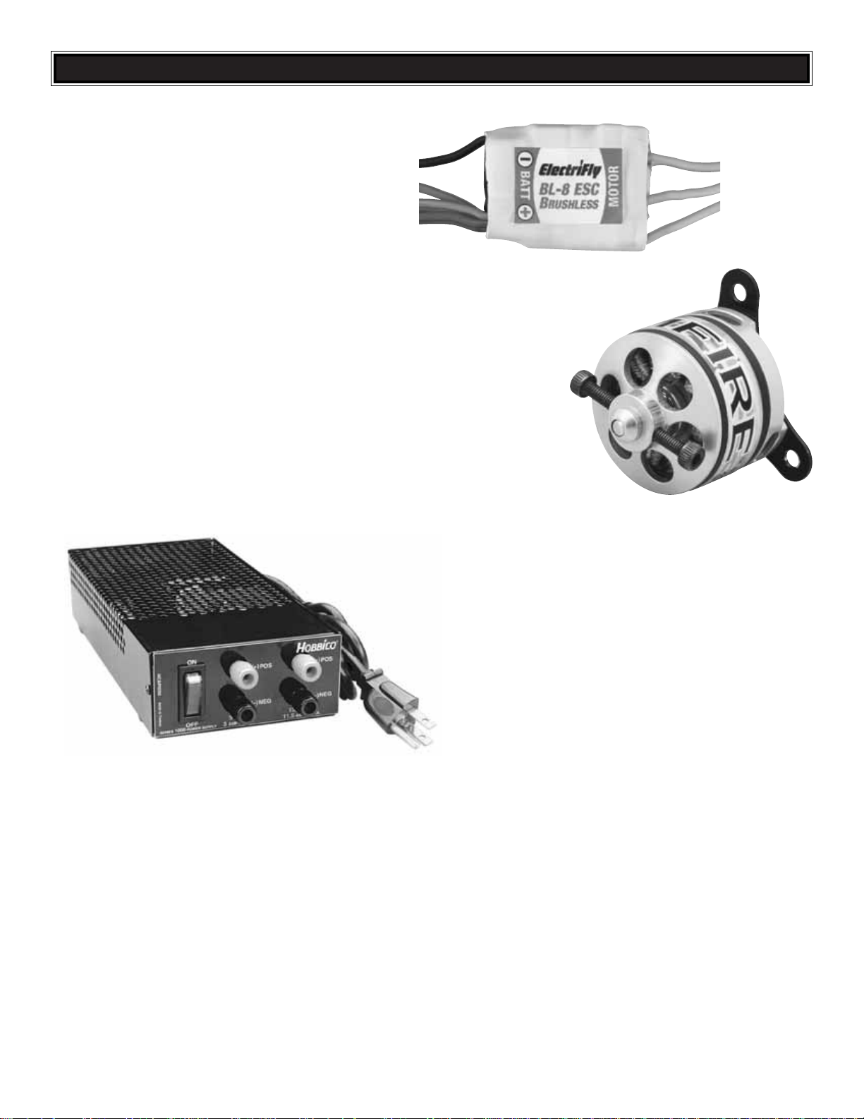
Hobbico®12V Power Supply
(HCAP0250)
The 12V Power Supply transforms 110V AC current into
constant 13.8V, 11.5A DC power for peak chargers, motor
break-in and more. It includes fuse protection, 5V tap, a
lighted on/off switch and one-year warranty protection.
ElectriFly™BL-8 Brushless Electronic
Speed Control (GPMM2070)
ElectriFly’s BL-8 is a fully proportional forward/reverse
ESC with brake. Compatible with NiCd, NiMH, and Li-Po
batteries, it has custom BEC that handles up to
1.5A–perfect for models that use up to three high-po wered
servos.Programmable f eatures include brake control, saf e
start, and switching frequency.
ElectriFly™RimFire™22M-1000 Brushless Motor
(GPMG4500)
Perf ect f or small, high performance planes such as FlatOuts and smaller 3D aerobats,
the RimFire has an exceptionally high power-to-weight ratio and an efficiency rating
of 77%! Its “outrunner” design eliminates the need for an external gear drive, for
easier installation and less weight. Simply attach the prop to the motor with a rubber
band (no prop adapter required)…the prop will simply “pop” off in a crash.
Page 24
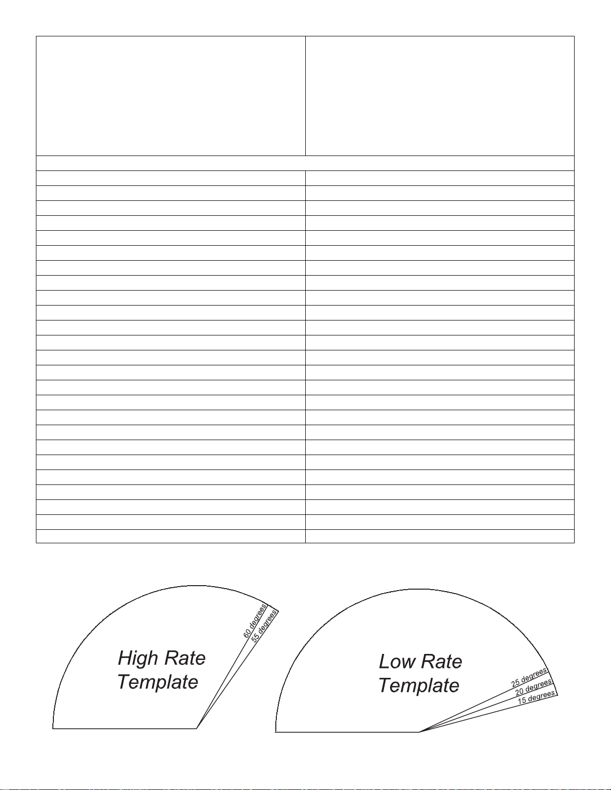
CONTROL SURFACE
ANGLE TEMPLA TES
BUILDING NOTES
Kit Purchased Date: _______________________
Where Purchased: _________________________
Date Construction Started: __________________
Date Construction Finished: _________________
Finished Weight: __________________________
Date of First Flight: ________________________
FLIGHT LOG
 Loading...